1
Adapter Installation
Turn off the personal computer and any other remote equipment before performing the
adapter installation. Never install or remove the adapter with the power applied to the PC
or any of the attached equipment. This could result in permanent damage to the adapter
due to static discharge.
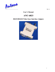
Normally the adapter is plugged directly into the serial port male DB-9 jack on the back of
the PC. The user should screw the 2 mounting screws into the serial port’s hex nuts for
permanent installations to assure good long-term connection.
The adapter may be attached to a ribbon cable type extension from the PC to the Antona
adapter. This is sometimes useful when the space is limited behind the PC. The ribbon cable
extension should not exceed 3 feet. A 12’ shielded wire cable could also be used. Remember
that the signal is still RS-232C level leaving the computer and entering the adapter. Also note
that if the designer is using a DB9 to DB25 adapter an A-B selector box or break-out box for
testing, that all 9 pins should be connected through the adapter or test setup. The main ANC6185 adapter power is drawn from the host system’s RTS and DTR lines, like a serial comport
mouse interface.
Serial Port Powering
Three of the PC’s serial port RS-232C level signals can be used by the Antona adapter to
derive power from: RTS, DTR and TX. The user must therefore insure that the RTS and DTR
signals from the PC’s serial port are brought to a high output level 100 ms before communicating
over the adapter. Usually this is performed once during the user’s program initialization. If
desired, with the appropriate jumper settings, RTS is lowered and raised to receive and transmit
respectively. In this mode, DTR must be left high to power the adapter when RTS is set low.
The adapter can be powered down by lowering RTS and DTR when standby current usage is an
issue (to conserve battery power for example).
External Powering
An external +3 to +12 Voltage source may be feed into pin 1 (marked ‘V’ on the board) , and the
power supply Ground connected to pin 6 (marked ‘G’ on the PCB), on the ANC-6185T terminal
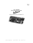
block version. See the right hand side of figure 1 below for the terminal block pinouts. Power is
wired to pin 4 on the and ground to pin 5 on the RJ-45 connector of the ANC-6185R version.
The table “RS-485/422 Connections to the ANC-6185” shows the pinouts for using an external
source of DC to power either adapter version.
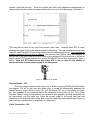
There are also two pads on the ANC-6185 circuit board you can solder leads to for applying
external power. A small hole in the plastic case would need to be added to run the power supply
leads away from the adapter. This may be useful in applications by using 2 spare wires to send
power to a remote adapter. An example would be where one externally powered ANC-6185
connected to a PC inside of an office sends power with the data signals to a roof mounted RS485 serial temperature reading monitor. Figure 1 below shows the pads as black dots. The
regulated +DC source is soldered to the pin located just to the right of JP7, and the power
supply ground pin is soldered to the pad just above JP4.
Antona Corporation
4
(818)783-4299