Download ANC-8000/9000 User`s Manual in PDF format
Transcript
Rev. H
$ 5.00
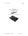
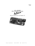
ANC-8000 / ANC-9000
LCC/PGA/PCC/QFP to Wire Wrap
Adapter Series
Antona Corporation, Los Angeles, Ca.
1643 1/2 Westwood Blvd., L.A., CA. 90024-5603
Tel:(310) 473-8995
***** BEFORE INSTALLING AND WIRING THE ADAPTER *****
1.
MAKE SURE THAT THE ENCLOSED ADAPTERS ARE THE
APPROPRIATE SOCKET TYPE FOR YOUR APPLICATION On initial orders, an LCC socket adapter is sometimes ordered when a
PLCC/PCC is what is needed.
2. MAKE SURE THAT THE SILKSCREEN NUMBERING MATCHES
YOUR PART This is a new packaging technology, so some devices are numbered
starting with pin 1 in the upper left-hand and some starting with pin 1 to the
upper center of the package. Some chip manufactures offer devices using both
numbering schemes. This may be a problem with the "J"-leaded (PLCC/PCC)
type packages. Electronically there is no problem, the silkscreen on the adapter
circuit board just will not match the real component pin numbering. The
enclosed adhesive backed numbering sheet could be used to re-label the
component side silkscreen on the adapter if necessary.
Copyright
Copyright (c) 1988, 1992 by Antona Corporation. All rights reserved. No
part of this publication may be reproduced, transmitted, transcribed, stored in a
retrieval system, or translated into any language or computer language, in any
form or by any means, electronic, mechanical, magnetic, optical, chemical,
manual or otherwise, without the prior written permission of the Antona
Corporation of Los Angeles, California.
Warranty
Antona Corporation products are warranted to be free from defects in
materials and workmanship for a period of one (1) year from the date of original
shipment to customer. This warranty is limited to the replacement or repair of
parts not subjected to misuse, neglect, unauthorized repair, alteration (except
jumper options), accident, or failure due to the effects of static electricity
discharge. In no event shall Antona Corporation be liable to the purchaser for
loss of use, profit, or consequential damages, or damages of any kind, including,
but not limited to, accidental loss or damage to other equipment, arising out of
use of Antona Corporation equipment, whether or not said equipment was used
properly. This warranty is in lieu of any other warranty, expressed, implied, or
statutory, including, without limitation, any implied warranty or merchantability or
fitness for a particular purpose. No amendment of this warranty may be effected
except in writing by an officer of the Antona Corporation. All repair services
shall be performed at the Antona Corporation plant in Los Angeles, CA. THE
PURCHASER MUST OBTAIN A RETURN AUTHORIZATION FROM THE
ANTONA CORPORATION PRIOR TO RETURNING ANY PIECE OF
EQUIPMENT. Shipment to the Antona Corporation will be at the expense of
the purchaser, return shipment will be at the expense of the Antona Corporation
for all warranty repairs.
1643 1/2 Westwood Blvd., L.A., CA. 90024-5603
Tel:(310) 473-8995
ANC-9000/8000(LCC/PGA/PCC WIRE WRAP ADAPTERS)
Introduction
Thank you for ordering our adapter products. Antona Corporation has
been producing process and monitoring control cards and systems since 1979.
Our engineers were eager to develop new card products for the industrial
control market using the new leadless chip packages, only to find that there
were few products available to interface the multi-pin leadless, plastic and pingrid chips to wire-wrap posts in order to prototype the initial design. During the
design debug stage, the difficulty in getting an oscilloscope probe onto the chip
produced a secondary problem. Locating a particular pin number on a package
with so many leads, and then holding the scope probe in place on the edge of a
lead with center-to-center spacing of 0.050" or less proved to be a frustrating
and possibly disastrous operation. Hand fabricating an adapter, depending on
the number of pins, requires 2-6 hours (and then may not work properly).
After developing an adapter series for in-house use which solved all
these problems, and at the encouragement of fellow engineers who had faced
the same problems, we introduced, in 1985, a line of adapters to accommodate
a wide variety of package types. In 1991, LEDs were added to the adapters to
provide a unique feature to aid in design test and debug.
The ANC-9000/8000 series provides a quick and efficient means for the
circuit designer to wire wrap prototypes of equipment using VLSI leadless and
leaded type packages. The adapter series was designed to bridge the
application gap between these types of components and the prototype stage of
system development. Occupying a minimum amount of card real estate, the
adapters provide labeled test points for each of the pins for the designer to
attach oscilloscope or logic analyzer probes. The wire wrap pins are on 0.3"
centered rows to allow the adapters to be used on a wide variety of prototype
boards. The tin plated pins extend .6 inch beyond the users prototype card
when .062 inch card is used. This is sufficient for 3 standard wire wraps to fit
on. All Antona adapter products are 100% electrically tested for proper
operation (pin-to-socket continuity and no short circuits).
If the adapter you ordered and received is not suitable for your particular
component just call and explain the problem - please include the component
part # and manufacture of the chip you are using if possible so we can add it to
our reference list. We can ship for next day delivery if need be.
3
Adapter Part Numbers
Our line of adapters has now grown to over 150 types including custom
versions. All of Antona's adapter products are designated: ANC-9PXXV (or
ANC-8PXXV for Test Socket Versions). Adapters are added to our product line
much faster than reprints of this manual, so check the Antona price list or
contact the factory if you are unable to locate the adapter version desired.
'XX' is the number of pins on the adapter socket (for sockets over 100
pins, use the lower 2 digits to specify the number of pins) and 'V' is the socket
version type as described below:
ANTONA Adapter pack/pin type
ANC-9 P - XX V
# of pins
Socket type
Package/Pin type specification
0 = PCC/PLCC/PGA/LCC with .025" square wire-wrap
5 = as above with .018" gold machine pins
1 = SOIC with .025" square wire-wrap pins
6 = as above with .018" gold machine pins
2 = Plastic Quad Flat Pack - PQFP with wire-wrap pins
7 = as above with .018" gold machine pins
Socket type specification
L = Leadless Chip Carrier - LCC (JEDEC type A,B,D), pin 1 in corner
T = LCC as above with pin 1 in center side of chip
P = Pin-Grid-Array - PGA, pin 1 in corner of chip
U = PGA as above with pin 1 in center of chip
J = Plastic Chip Carrier - PLCC/PCC/J-Lead, pin 1 center side of chip
S = PCC as above with pin 1 in corner of chip
Hardware Considerations
At Antona, the adapter cards are 100% inspected before, during and after
assembly. The yellow dot on the adapter socket signifies that it has passed a
functional electronic test for open connections and shorts. But even with all our
testing and inspecting, the first time the product will actually be used in
an electronic circuit application will be by you. Please take a few minutes
and inspect the adapter to your satisfaction. If an engineer or technician ran a
simple continuity and short test on the 160-pin adapter, it would take about 20
minutes maximum. Once all of the wire-wrapping has been completed, it will be
nearly impossible to fix a broken socket lead or trace if it is located between the
adapter card and the prototype card. If you find something you are not happy
about, call us. Our policy is simple, if the adapter has been paid for, a
replacement will be shipped that day. If the item was shipped on open account,
just return the adapter to us for a replacement.
4
I know, as a working engineer since 1973, that about the last thing
checked for on a design being debugged is a bad socket. The first thing
suspected is the design (the design task the other engineer was responsible
for), then the wire wrapping, then the software, and then the operation of the
component. Somewhere, way down the list of suspected problems, is the
socket. Take as much time and caution as the worse-case possibilities warrant.
Adapter Mounting
The adapters should easily fit on any prototype card which has been laid
out to accept industry standard .3" spaced rows of .1" spaced pins (except the
ANC-8260 adapter which uses .1" spaced rows). Some of our customers just
cut a hole out to match the adapter footprint. Make sure that once the Antona
adapter has been installed in the prototype card that there are no conductive
paths (bypass capacitors, component pins, etc.) under the adapter's socket
which might short to the adapter socket itself. The black plastic carrier, on the
bottom of the adapter socket, provides a .1" space between the users prototype
card and the adapter, but the socket leads sometimes come very close to the
prototype card depending on the manufacture of the socket. The designer
should take a few extra precautions when using the new generation of chips.
Spending a little extra time up-front will save a lot of grief (and rework) if a
problem is caught early enough.
Mounting Area for PCC/LCC/PGA/PQFP packages
# of socket pins
length width
square inches
20
1.2"
1.3"
1.6"
28/32
1.4"
1.3"
2.0"
44
1.8"
1.6"
2.9"
52
1.9"
1.6"
3.0"
68
2.2"
1.9"
4.2"
84
2.5"
2.2"
5.5"
100
2.7"
2.2"
6.0"
132
3.3"
2.1"
6.6"
132
2.6"
2.8"
7.3"
160
3.1"
2.6"
8.0"
Comment
PQFP
PQFP
PGA
QFP
Adapter Wire Wrapping
Note first of all, that with so many pins, getting out-of-step by missing or
jumping over 1 pin will require unwrapping many wire wraps, and that is if you
only have 1 wrap per pin. Use the enclosed adhesive backed pin
numbering sheet to label the pins on the wire wrap side of the
prototype card. The enclosed sheet is also handy for labeling pins on any
other component or connector pins on the user prototype card. Suggested
application of the numbering sheet is attached to the adhesive sheet itself.
Once the pins on the adapter have been labeled on the wire wrap side of the
5
card, locating the correct pin number to wire to will be a snap and the chance of
mis-wrapping a connection will go way down. Frequent checks of pin wiring by
continuity testing is highly recommended. Use the silkscreened pin numbers on
the top side of the adapter for this process. Try to avoid wiring more than 2
wraps per post. As the design debug process proceeds, you may need to add a
3rd wrap (along with adding IC's, assured if it's one of my designs). If the
lettered pins, which may be used to connect to the on-board LEDs and/or
corners of the socket, on the adapter are not being used, bend them over to a
45 degree angle to help prevent getting out-of-phase.
Machine Pin Adapter
The same basic problems can crop up with the machine pin as the wire
wrap versions of the adapter. Gently pry-up the adapter if it is necessary to
unplug the adapter from the prototype board because the gold pins are only
.018" diameter and are very fragile. If you do break one of the pins, they can be
individually replaced with the proper desoldering and replacement pins (call
Antona for replacement gold pins, within reason, they will be shipped free).
Component Installation
Do not install the target chip until all wire wrapping is done. It is probably
a good idea to measure the power supplies going to the chip adapter with a
voltmeter or scope before chip installation. Take a second look at the chip once
you have put it into the socket to insure correct pin 1 positioning. With the
leadless chips (LCC) it is almost impossible to not install it correctly because the
metal cover will not close properly if installation is incorrect. The plastic chips or
J-bent leaded parts (PCC/PLCC), have a corner cut away which the designer
should install matching the upper-left corner of the PLCC socket located in the
same corner as the cut-away corner of the adapter circuit board itself. The
PLCC chips require a special tool to remove the chip once they are installed.
Antona offers a low cost PLCC removal tool (ANC-EX3M, $23.00), and includes
the tool free with initial adapter orders totaling $300.00 or more. The pin-gridarray (PGA) chips look like disaster in the waiting as they may be plugged into
the PGA adapter card versions in 4 different ways with equal ease. Make sure
that pin 1 is properly positioned before applying power to the system. If the
PGA chip is to be removed from the adapter socket, use extreme care when
prying up the chip. A special PGA removal tool is highly recommended. Plastic
Quad Flat Package (PQFP) parts have the potential to be misinstalled also. Be
sure to identify pin 1 on the chip, place the part into the cover piece and then
carefully press the device and cover onto the adapter socket body. The 3M
PQFP sockets are shipped with the installation tool, the AMP PQFP socket
installation is described in Appendix A.
Power and Ground Considerations
The designer should place bypass capacitors (.1 ufd) and a filter
capacitor (15 ufd ) as near as possible to the adapter package wired to the Vcc
6
and GND of the chip. Keep the power and ground wires to the adapter as short
as possible. Solder connections wherever possible to power the chip. Many of
the leadless chips have multiple Vcc and GND connections, be sure to use all of
them. Most of the ANTONA adapters have .015" traces of 1 ounce copper,
which means each trace is rated at 1 Amp of current with a 20 degree C
temperature rise above ambient. All versions have .030" traces on as many of
the solder side pins as possible. It is noted that there seems to be no standard
pins set aside for Vcc and GND connections from manufacturer to
manufacturer. Depending on the particular component that the designer is
using, additional heat sinking may also be required for proper operation of the
part. With the 68-pin LCC adapter, special heat-sink covers are available from
Antona.
Adapter Socket Components
The most important socket attributes are availability and price. After
trying several different manufacturers' sockets, and listening to our customers
preferences, we have settled on a mixture of sockets for use on the various
versions of the adapter cards. The widest range of PLCC type components
seem to be best accommodated by Yamaichi sockets and customers seem to
prefer the AMP sockets for LCC type devices. The wire wrap pins on the ANC90XX/80XX adapters are tin plated 0.025" square posts. The gold plated
machine pins on the ANC-95XX/96XX versions are 0.018" diameter and 0.150"
long. If your particular application requires that a specific socket be
used, gold plated wire wrap posts, or .020" machine pins, etc., you
may inquire with Antona Corporation about a custom run of adapters
built to your specifications with a 6 piece minimum order.
Light Emitting Diode (LED) Feature
Beginning in 1991, we started adding LEDs to the adapters as new
batches of cards were manufactured. Access to the LEDs is very straightforward. There are separate wire wrap leads (in no way connected to the
component socket) which the designer may use to monitor supply voltage to the
adapter and/or any user selected signal that can sink the 6 to 8 mA of current
necessary to light the LED. This feature is unique to the Antona chip adapter
and chip test product line. Connect a +5v source to the L1+ and a GND sink to
L1- for LED 1 (ditto for LED 2 using L2+, L2-).
Adapter Pin Arrangement
The following pages contain enlargements of the silk-screen used on the
adapter circuit cards. The designer may use these as a layout sheet and debug
aid by annotating the pin functions of the particular chip being prototyped
directly onto this sheet. The pin numbering follows two possible schemes, pin 1
in the upper-left corner (usually for LCC/PGA) or pin 1 in the upper-center of the
7
package (usually for PLCC-PCC). It is not clear to the author why the
numbering is not standardized using the former numbering scheme.
The basing diagrams are currently being converted for the
internet.
8


