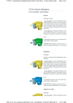
1
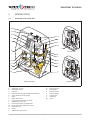
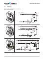
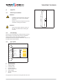
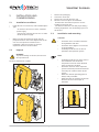
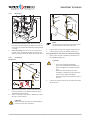
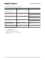
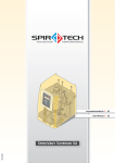
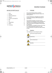
SPIROVENT SUPERIOR
TABLE OF CONTENTS
1
User manual 60.486
English
/i
1
Preface
29
2
Introduction
30
3
Technical specifications
34
4
Safety
36
5
Installation and commissioning
37
6
Use
43
7
Failures
45
8
Maintenance
49
9
Guarantee
52
10 CE statement
52
PREFACE
This user manual describes the installation,
commissioning and operation of the SpiroVent Superior,
types:
/i
Type
Article code
- S6A
MA06A..
- S6A-R
MA06R..
- S6A-R 2P
MA06P..
- S10A
MA10A..
- S10A-R
MA10R..
- S16A
MA16A..
- S16A-R
MA16R..
Read the instructions before installation, commissioning
and operation. Keep the instructions for future reference.
All rights reserved. No part of this manual may be
duplicated and/or made public through the Internet, by
means of printing, photocopying, microfilm or in any
other way without prior written permission from
Spirotech bv.
This manual has been composed with the utmost care.
Should, however, this manual contain any inaccuracies,
Spirotech bv cannot be held responsible for this.
1.1
Symbols
Throughout the instructions the following symbols are
used:
Warning or important note
Note
Risk of electric shock
Risk of burning
User manual - 2.0
English
29
SPIROVENT SUPERIOR
2
INTRODUCTION
2.1
Overview of the unit (S6)
W
V
U
A
T
B
S
C
D
S
R
Superior S6A
E
F
Q
G
P
H
O
I
N
K
M
Superior S6A-R 2P
A
B
C
D
E
F
G
H
I
K
M
N
O
P
30
Automatic air vent
Deaeration vessel
Inlet line
Refill connection (types S6A-R and S6A-R 2P)
Valve (before pressure gauge)
Bolts
Water flow meter
Level switch (in bottom of vessel)
Adjustment valve inlet
Back-up pump (for type S6A-R 2P)
Drain connection (under the vessel)
Solenoid valve
Pump
Adjustment valve outlet
Superior S6A-R
Q
R
S
T
U
V
W
English
Pressure sensor
SmartSwitch
Pressure switch
Pressure gauge
Control unit
Outlet line
Cover
User manual - 2.0
SPIROVENT SUPERIOR
2.2
Overview of the unit (S10 and S16)
W
V
U
C
D
J
A
S
B
R
F
O
E
S
T
Q
N
P
G
Superior S10A / S16A
I
K
H
N
M
Superior S10A-R / S16A-R
A
B
C
D
E
F
G
H
I
J
K
M
N
Automatic air vent
Deaeration vessel
Inlet line
Refill connection (S10A-R and S16A-R)
Valve (before pressure gauge)
Bolts
Water flow meter
Level switch (in bottom of vessel)
Adjustment valve inlet
Pressure switch discharge outlet (S10A and S16A)
Flow-back limiter
Drain connection
Solenoid valve
User manual - 2.0
O
P
Q
R
S
T
U
V
W
English
Pump
Adjustment valve outlet
Pressure sensor (S10A-R and S16A-R)
SmartSwitch
Pressure switch
Pressure gauge
Control unit
Outlet line
Cover
31
SPIROVENT SUPERIOR
2.3
Operation
/i
The figures below schematically show the operation of
the unit. The letter indications correspond with the main
figure on the previous pages.
C
I
PS
R
PI
N
T
A
E
S
PS
M
B
H
LS
V P
S6A
O
M
S
6
A
R
C
I
PS
R
D
FT
N
PI
A
E
G
S
Q
N
T
PS
M
B
PT
LS
V
S6A-R
H
P
O
M
S
6
A
R
C
I
R
D
FT
M
N
A
G
M
N
T
PS
B
K
PT
PS
E
S
Q
PI
LS
S6A-R 2P
32
V
2
P
H
P
O
English
M
User manual - 2.0
SPIROVENT SUPERIOR
I
C
PS
R
N
A
E
S
M
J
V
T
PI
PS
B
PS
H
P
LS
O
Superior S10A/ Superior S16A
M
I
C
PS
R
D
N
N
A
FT
G
E
S
M
Q
V
B
P
2.3.1
General
The SpiroVent Superior is a fully automatic vacuum
degasser for installations filled with fluid. Fluids contain
dissolved and free gases. The unit removes these gases
from the installation. Problems caused by gases in the
installation are thus prevented.
2.3.2
Degassing
The unit starts up a degassing process each day at a time
set by the user. The process has two phases:
1
The rinsing phase: The fluid flows from the
installation through the solenoid valve (N) into the
vessel (B). The pump (O) continuously pumps the
fluid from the vessel into the installation. Here the
fluid absorbs gases present in the installation.
2
The vacuum phase: The solenoid valve (N) regularly
closes, starting a vacuum phase. The continuously
running pump (O) provides underpressure in the
vessel (B). The underpressure causes the release of
the gases dissolved in the fluid, which are collected
at the top of the vessel. The gases are removed
from the installation through the automatic air vent
(A). The SmartSwitch (R) at the automatic air vent
makes sure that the degassing is stopped as soon as
User manual - 2.0
PI
PS
PT
Superior S10A-R / Superior S16A-R
T
H
O
LS
M
the content of dissolved gases has reached the
minimum level. The solenoid valve (N) opens again,
at the end of the vacuum phase.
2.3.3
(Re)filling
The SpiroVent Superior S6A-R, S6A-R 2P, S10A-R and
S16A-R have an integrated refill function.
A unit with a refill function can control the pressure of
the installation. To control the pressure, the unit inserts
additional degassed fluid into the installation, if
necessary. The unit can also fill the entire installation with
degassed fluid.
2.3.4
Back-up pump
The SpiroVent S6A-R 2P also has a back-up pump. In case
of a break-down of the main pump, the back-up pump
takes over the refill function of the main pump, without
degassing.
English
33
SPIROVENT SUPERIOR
2.4
Operating conditions
The unit is suitable for use in systems filled with clean
water or mixtures of water with a maximum of 40%
glycol. Use in combination with other fluids may result in
irreparable damage.
3
TECHNICAL SPECIFICATIONS
3.1
Dimensions
The unit should be used within the limits of the technical
specifications as given in chapter 3.
WARNING
•
•
2.5
H
In case of doubt, always contact the
supplier.
In case of a heavily contaminated system
fluid, install a dirt separator or filter in
the main return line of the installation.
Scope of delivery
D
1x SpiroVent Superior
1x User manual
1x Non-return protection (optional)
•
•
•
3.2
W
/i
Model
Height
[mm]
Width
[mm]
Depth
[mm]
S6
880
590
350
S10/S16
1272
744
400
General specifications
/i
General specicfications
S6A
Max. system volume
m3
Empty weight
kg
Noise level
dB(A)
Volume of degassing
vessel
L
S6A-R
S6A-R 2P
S10A
S16A
S10A-R
S16A-R
90
82
92
300
58
59
68
80
<70 (57)
8
Inlet connection
Swivel G¾” f.t.
Outlet connection
Swivel G¾” f.t.
Refill connection
n/a
Swivel G¾” f.t.
Drain connection
34
n/a
Swivel G¾” f.t.
Swivel G¾” m.t.
English
User manual - 2.0
SPIROVENT SUPERIOR
3.3
Electrical specifications
/i
Electrical specicfications
S6A
S6A-R
S6A-R 2P
S10A
S16A
S10A-R
S16A-R
Supply voltage
-
Absorbed power
W
1150
1150
1650
1550
2250
1550
2250
Nominal power consumption
A
5,9
5,9
7,9
3,0
4,3
3,0
4,3
Protection
A(T)
Max. load of potential-free
contacts
-
230 V ± 10% / 50 or 60 Hz
10/3,5
24V/1A
Supply voltage for BMS control Vac
(voltage of BMS)
Supply voltage of external refill
signal (supplied voltage)
Vdc
Protection class
-
3.4
3 × 400V ±10% 50Hz (60Hz upon
request)
24 (to be supplied)
n/a
5 (suplied)
n/a
5 (suplied)
IP x4D
Other specifications
/i
Other specicfications
S6A
S6A-R
S6A-R 2P
S16A
S10A-R
S16A-R
5..10
9..16
5..10
9..16
25
16
25
n/a
See graph in § 6.1
System pressure
bar
Ambient temperature
°C
0..40
System fluid temperature
°C
0..90
Maximum compression
pressure (with closed valve
behind pressure gauge)
bar
Refill flow
l/hr
n/a
Refill pressure
bar
n/a
0..6
n/a
0..10
Refill fluid temperature
°C
n/a
0..70
n/a
0..70
3.5
1..6
S10A
10
16
See graph in § 6.1
Building Management System
(BMS)
/i
The unit is provided with auxiliary contacts for
communication with a BMS or other external system. The
BMS must offer a 24Vac voltage.
CAUTION
•
Signal
The unit failure signal must not be used
as a boiler interlock.
S6A
S6A-R
S6A-R 2P
S10A
Unit in
operation
Potential-free
Unit failure
Potential-free
Unit release/
stop
24 Vac
Refill by BMS
n/a
User manual - 2.0
24 Vac
24 Vac
n/a
English
S16A
S10A-R
S16A-R
n/a
24 Vac
24 Vac
35
SPIROVENT SUPERIOR
4
SAFETY
4.1
General precautions
WARNING
•
•
Installation and maintenance of the unit
should only be carried out by qualified
personnel.
Remove the power and pressure from the
unit before starting the activities.
WARNING
•
4.2
There are hot parts under the cover. Let
the unit cool down before starting the
activities.
CE marking
The unit has a CE marking. This means that the unit has
been designed, constructed and tested in compliance
with the current safety and health regulations.
Provided that the user manual is adhered to, the unit can
be safely used and maintained.
4.3
Type plate
A
B
C
D
E
SPIROVENT SUPERIOR
Article-No.:
Type:
Power input:
Voltage / Frequency:
IP class:
Pressure PS:
Temperature TS:
F
Serial no.:
Year of manufacture:
G
Weight:
Spirotech bv - The Netherlands
H
I
A
B
C
D
E
F
G
H
I
Type of the unit
Absorbed power
Supply voltage
Protection class
System pressure
System temperature
Serial number
Year of construction
Weight
The type plate can be found on the right side of the unit.
36
English
User manual - 2.0
SPIROVENT SUPERIOR
5
INSTALLATION AND
COMMISSIONING
5.1
Installation conditions
•
•
•
1.
2.
3.
4.
-
Install the unit on a frost-free, well-ventilated place.
Type:
S6: Connect the unit to a 230 V / 50-60 Hz
power supply.
S10 and S16: Connect the unit to a 3 x 400 V
/ 50-60 Hz power supply.
-
5.3
Make sure that the expansion system has the
proper dimensions. The water displacement in the
unit can cause pressure variations in the
installation. Take into account an extra net
expansion volume of at least 8 litres.
5.2
Remove the packaging.
Loosen the screws (A).
Remove the cover (B) from the unit.
Move the unit to its place of installation.
S6: Move the unit with two persons. Use the
handles (C) to lift the unit.
S10 and S16: Move the unit with proper lifting /
hoisting equipement. Use the hoisting eyes (C) to
lift the unit.
Installation and mounting
CAUTION
•
•
Install the unit in accordance with the
local guidelines and rules.
Install the unit as bypass to a main line
of the installation.
Preferably install the unit as close as
possible to the expansion system.
Unpack
•
WARNING
To prevent damage to the unit, do not hoist
the unpacked unit.
NOTE
•
The unit is delivered on a pallet.
A
B
S6
•
•
•
Preferably install the unit at the point in
the installation with the lowest
temperature. Here the most dissolved
gases are found in the fluid.
Install the unit close to the expansion
system to minimise pressure fluctuations
caused by the intake of water by the
system.
Make sure that the operating panel is
always easily accessible.
Make sure that you maintain at least the
distance for service and repair as
indicated.
•
A C
S10-S16
C
A
60cm
60cm
B
User manual - 2.0
English
37
SPIROVENT SUPERIOR
5.3.1
Mounting
A
B Ø10
D
B
C
E
F
G
A
1.
2.
Wall mounting (only for S6): Mount the unit on
the wall by using the holes (B). Make sure that the
mounting can support the filled unit (empty weight
± 10 kg).
Floor mounting: Place the unit on a flat surface,
against a flat, closed wall. Mount the unit on the
floor by using the holes (A) (S6:∅10, S10/S16: ∅11).
5.3.2
Installation
NOTE
As seen from the direction of the volume flow,
the first branch is the inlet of the unit.
3.
4.
Connect the line (A) to the flexible outlet line (D).
Connect the line (B) to the flexible inlet line (C).
Only applicable to units with the refill functionality:
1.
Insert a valve (F) and a backflow protection (E) in
the refill fluid supply line.
Mechanical
CAUTION
•
> 500mm
A
B
•
•
A
B
1.
2.
Use a locally approved backflow
protection. A backflow protection can
also be supplied as an option with the
unit.
Make sure that the pressure of the
feedwater is below the system pressure.
This prevents undesired refilling.
Make sure that the lines leave the unit at
the rear.
2.
Connect the make up water to the refill connection
(G) of the unit.
English
User manual - 2.0
Make two branch lines ¾” (A) on the side of the
main transport line. The distance between them
should be at least 500 mm.
Insert a valve (B) in each branch. With these valves
the unit can be isolated.
CAUTION
Make sure that the valves are opened before
putting the unit into operation.
38
SPIROVENT SUPERIOR
Electrical
1
2
L = 9mm
CAUTION
Preferably use a wall socket for the
power supply to the unit. The socket
should remain accessible.
Mount an all-pole main switch (contact
opening >= 3mm) if the unit is directly
connected to the power supply.
Use supply cables with the correct
dimensions.
Always replace a defective fuse with a
fuse of the same value, see § 3.3.
•
•
•
•
PE
N
L3
L2
T >70°C
L1
3
1
2
L = 9mm
A
PE
N
L1
T >70°C
3
1.
S6: Feed a 3-core supply cable through swivel (A).
S10 and S16: Feed a 5-core supply cable through the
swivel (A).
2.
Insert the wires as indicated into the connector.
4
3.
User manual - 2.0
English
Insert the connector into receptable J16.
39
SPIROVENT SUPERIOR
3.
4.
F7 F6 F5 F8 F1
Open the valve (C) before the pressure gauge (D).
Open the valves (E and F) in the inlet and outlet
lines.
Only applicable to units with the refill functionality:
Open the valve (G) in the refill line.
5.
J21
J16
J20
F2
NOTE
The pressure in the vessel during the flushing
phase should increase from vacuum up to
overpressure within 10 seconds. If it takes
longer, turn the adjustment valve (B) fully
open and then back to a position¼ higher
than the actual position.
J2
1 2
J2 1
0 8
1
6
/i
J1 1
6
4.
If a BMS or other external system is used, use
connector J20 to connect to that device.
Only applicable to units with the refill functionality:
If another external device controls the refill, use
connector J21 to connect to that device.
5.
product
type
S6
/i
system
pressure [bar]
inlet (B)1)
outlet (A)
1..2
3
2
2..3
2½
2½
3..4
2¼
6
4..5
2
6
connector
contact
connection
5..6
1¾
6
J20
1 and 2
Unit ready
5..6
6
1¾
3 and 4
Failure
6..7
3¼
1¾
5 and 6
On/off
7..8
3
1¾
7 and 8
Refill1)
8..9
3
2½
1 and 2
1)
9..10
¾
6
9..10
6
1½
10..11
3
1½
11..12
3
1½
12..13
2¾
1½
13..14
2¾
1½
14..15
2½
1½
15..16
2½
1¾
J21
Refill
S10
1) only applicable to units with the refill functionality.
5.4
Commissioning
5.4.1
Preparation
F
S16
E
1) In case of water-glycol mixtures, foaming
may occur dependent on glycol quality, system
pressure, gas content and glycol rate. This may
lead to malfunction of the superior. Open the
inlet valve to max 6 to resolve this (temporary)
error.
G
C
A
D
B
1.
2.
40
Close the valves (E and F) in the inlet and outlet
lines.
Set the adjustment valves from the position “fully
open” as specified in the table.
English
User manual - 2.0
SPIROVENT SUPERIOR
5.4.2
Start up
5.4.3
A
Filling the unit
A
B
C
A
B
C
D
E
F
G
H
I
I
D
H
E
G
F
On/off
Display
Status report in operation / OK (green LED)
Up
Confirm / Enter
Menu
Down
Cancel / Exit
Status report failure (red LED)
1.
2.
3.
4.
5.
6.
7.
CAUTION
•
•
The start-up routine starts automatically
when the unit is switched on for the first
time.
Press EXIT to go back one step in the
menu while programming.
Set date and time
1.
Press ON/OFF.
2.
Select a language using S and T. Press ENTER.
3.
Set the date using S and T. Press ENTER.
4.
Set the day using S and T. Press ENTER.
5.
Set the time using S and T. Press ENTER.
8.
9.
See § 5.4.1 for the settings of the valves.
Press ENTER two times. The unit starts filling.
Wait for 20 seconds until Initial fill busy
disappears.
Loosen the air vent screw (A) a few turns and
tighten it again when air has stopped coming out.
Repeat steps 1 - 3 until water starts coming out of
the air vent screw at step 3.
Also deaerate the back-up pump with type S6A-R 2.
Press EXIT two times. The status menu shows the
message Err 7 when the test of the run dry
protection has been completed successfully.
Press MENU. Select Manual operation using S
and T. Press ENTER.
Select Reset using S and T. Press ENTER.
NOTE
When the green LED is lit this indicates that
the unit is ready for use. Degassing starts by
default every day at 08:00 hours.
5.4.4
Check operation
D
A
B
C
1.
User manual - 2.0
English
Manually start the unit, see § 5.5.2.
41
SPIROVENT SUPERIOR
2.
3.
4.
Check the indication of the pressure gauge (B). This
should alternately display overpressure and
underpressure.
Close the valve (A) before the pressure gauge (B).
Put back the cover (C) on the unit and fasten it with
the bolts (D).
NOTE
The SmartSwitch will automatically turn
off the unit when the concentration of
dissolved gases has reached the minimum
level.
5.5
Install and operate
5.5.1
Set the user parameters
1.
2.
3.
4.
5.
Press MENU. Select Settings using S and T. Press
ENTER.
Select the parameter to be changed using S and
T. Press ENTER.
Change the setting using S and T. Press ENTER.
Repeat steps 2 and 3, if necessary.
Repeatedly press EXIT to return to the status report.
Parameter
Psystem desired
Description
1)
Pressure at which the refilling
stops. Set this as low as possible
if the refilling is controlled by a
BMS or an external device.
Refill pressure1)
Pressure at which the refilling
starts. Set this point as low as
possible when the refilling is
controlled by a BMS or other
external device.
Refill alarm1)
Maximum allowed refill quantity
per refill. Issues an alarm if a
refill exceeds this threshold. (0 2500 l; 0 = switched off).
Refill alarm after1)
Maximum continuous refill time
(0 - 255 min.; 0 = switched off).
Max. refill freq.1)
Maximum number of times per
day that refilling is allowed
(0 - 10 times; 0 = switched off).
1) Only for units with the refill functionality.
5.5.2
Manual operation
/i
NOTE
If manually switched off, the process must be
manually switched on again.
Parameter
Description
Language
Language for the display texts.
Date
The current date.
Weekday
The current day of the week.
Time
The current time.
Auto start 1
Time 1 for starting the
degassing process.
Auto start 2
See Auto start 1.
Block.time day 1
Time for stopping the degassing
process.
Block.time day 2
See Block.time day 1.
Block.time week
Days of the week on which the
unit is not working.
1.
2.
5.5.3
Filling the installation
Only applicable to units with the refill functionality.
1.
Press MENU. Select User menu > Manual
operation using S and T. Press ENTER.
2.
Select Manual operation > system fill
using S and T. Press ENTER.
3.
Select Degassed or Not degassed. Press ENTER.
NOTE
When desired system pressure is reached, see
Psystem desired in § 5.5.1. The unit enters
the standby status and filling stops.
Selected days are marked with
an *.
After having changed this
parameter, select Save using S
or T. Press ENTER.
Block.time year 1
Period per year during which
the unit is not working.
Block.time year 2 - 5
See Block.time year 1.
Max. syst. pressure 1) Pressure at which the unit stops
and flags an alarm.
42
Press MENU. Select User menu > Manual
operation using S and T. Press ENTER.
Select Manual operation start or Manual
operation stop using S and T. Press ENTER.
5.5.4
Switch on again
Follow the procedure described below after the unit has
been switched off.
1.
Set the adjustment valves from position "fully open"
in accordance with the table in § 5.4.1.
2.
Follow the procedure described in § 5.4.3.
English
User manual - 2.0
SPIROVENT SUPERIOR
5.5.5
Reading statistics
During operation the following data are stored in the
memory:
•
Accumulative running hours
•
Degassing history
•
Fault history
•
Refill history if applicable.
The memory can be read in the following way:
1.
Press MENU. Select User menu > History using S
and T. Press ENTER.
2.
Select Fault history or Operation history
using S and T. Press ENTER.
3.
Select an item using S and T. Press ENTER.
4.
Repeatedly press EXIT to return to the status report.
S6
600
500
B
USE
6.1
General
•
•
•
•
•
•
6.2
300
200
100
0
0
1
2
3
4
5
ΔP
S10
5.5.6
Reading data
The following general data has been stored in the
memory of the unit:
•
Unit type
•
Software version
•
Installation date
•
Common fault
•
Trial period
The general data can be read in the following way:
1.
Press MENU.
2.
Select User menu > General info using S and
T. Press ENTER.
3.
Select an item using S and T. Press ENTER.
4.
Repeatedly press EXIT to return to the status report.
6
400
700
600
B
8 - 10 bar
system pressure
500
5 - 8 bar
400
300
200
0
1
2
3
4
5
6
7
8
9
10
ΔP
S16
700
600
B
14 - 16 bar
system pressure
500
The display is lit automatically after a key has been
pressed.
The display dims automatically after no key has
been pressed for 5 minutes.
While stopping the process a stop procedure is
started, making sure that the unit stops in a safe
situation (overpressure).
When a pump has not run for 96 hours, an
automatic pump test is run at the first next Auto
start.
Press ON/OFF to switch off the unit. Press ON/OFF
again to switch on the unit again.
At low fluid temperatures condensation may occur
at certain parts. The condensation is drained
through the openings in the frame. Insulated
versions are also available to prevent condensation.
400
9 - 14 bar
system pressure
300
200
0 1 2 3 4 5 6 7 8 9 10 11 12 13 14 15 16
ΔP
/i
ǻP
Pressure difference between system and mains
water (bar)
B
Flow (litres/hour)
Refill
Only applicable to units with the refill function.
The amount of fluid that is added (B) depends on the
difference (A) between the system pressure and the main
water pressure.
User manual - 2.0
English
43
SPIROVENT SUPERIOR
6.3
Status reports
/i
Report
Description
LED indication
Auto pump test
The unit runs a pump test.
Green
End degassing
The stop procedure is in progress.
Green
Degassing
The unit is degassing.
Green
Process stopped
The unit has been stopped manually.
None
Standby
The unit is waiting for a starting signal.
Green
Stop by BMS
The BMS has stopped the unit. After release by the BMS the status is
‘standby’
None
Failure
The unit has stopped because of a failure. Remedy the failure before
resetting the unit, see § 7.4. The unit is switched to one of the above
statuses.
Red
The unit is refilling fluid.
Green
The installation is filled with fluid.
Green
End refilling1)
End systemfill1)
Refill1)
Fill system
1)
1) Only applicable to units with the refill functionality.
44
English
User manual - 2.0
SPIROVENT SUPERIOR
7
FAILURES
7.1
Remedy failures
WARNING
WARNING
•
•
•
•
7.2
In case of a failure always warn the
installer.
Remove the power and pressure from
the unit before starting repairs. See §7.2
on how to put the unit out of operation.
Pressing ON/OFF does not remove the
power from the unit.
Putting out of operation
B
WARNING
•
E
There are hot parts under the cover. Let
the unit cool down before starting
repairs.
In case of a failure the red LED comes
on. The display shows the failure report.
1.
2.
3.
4.
1.
2.
3.
NOTE
•
A
F
NOTE
•
Make sure that it is not possible to
supply power to the system
unintentionally.
Only applicable to units with the refill
functionality: The seriousness of the
failure determines whether the whole
unit or a part of the unit switches off.
The refill process can remain active
when a failure has been detected. In this
case both the red and the green LED
come on.
4.
5.
6.
7.
D
C
H
G
If the unit is switched on, Press ON/OFF to stop the
unit.
Take the plug out of the wall socket, if applicable.
Close the valves (A) and/or (C) in the inlet line and
(B) and/or (D) in the outlet line.
Close, if applicable, the valve (E) in the refill supply
line (F) as well.
Connect a drain line (H) to the drain connection (G).
Drain the unit through the drain connection (G).
Open the air vent screw on the main pump to
completely empty the unit. See the figure in §
5.4.2.
Use the failure table in §7.3 to localise the cause.
If necessary, put the unit out of operation, see §7.2.
Remedy the failure.
Reset the unit (see §7.4) or put the unit into
operation again (see §5.5.4).
User manual - 2.0
English
45
SPIROVENT SUPERIOR
7.3
Failure table
The character indications correspond with the main
figures in § 2.1 and § 2.2. An overview of the replacement
parts has been included in § 8.2.
General
Problem
Possible cause
Correction
Err 5 Entrance flow
The solenoid valve (N) in the inlet line
does not open.
Replace (a part of) the solenoid valve.
A valve in the inlet line is closed.
Open the valve.
The inlet line has been blocked.
Remove the obstruction.
The pressure switch (S) is defective.
Replace the pressure switch.
Critical setting adjustment valve inlet
(I).
Turn adjustment valve ¼ position up
(from fully open).
Cable to pressure switch (S)
disconnected or interrupted.
Replace the cable. Replace the cable
lugs.
The adjustment valve (P) inlet has not
been set correctly.
Turn the adjustment valve outlet to
the correct position (see § 5.4.1).
One of the solenoid valves (N) is not
closing.
Clean valve internally. If necessary,
replace (a part of) the solenoid valve.
The valve in the outlet line is closed.
Open the valve.
The outlet line has been blocked.
Remove the obstruction.
The pump (O) does not run.
Check the pump. Check and replace
the pump fuse in the control unit.
The pressure switch (S) is defective.
Replace the pressure switch.
The automatic air vent (A) is blocked.
Replace the automatic air vent.
Pump stopped due to overheating.
Check the seal of the pump. Replace
the seal if necessary.
The flow in the inlet line has been
blocked 1).
Err 6 Flow
The flow in the outlet line has been
blocked 1).
Do a check on the thermistor or PTC
of the pump. Replace the Thermistor/
PCT pump if necessary.
Err 7 Fluid lack vessel
There is a risk of running dry, the fluid
level in the vessel is at the minimum.
Err 8 Pump is too hot
Pump is overloaded.
Err 9 Pump overloaded
Pump overloaded too often.
Err 17 Incorrect phase seq.
The automatic air vent (A) is defective
or blocked.
Replace the automatic air vent.
The vessel has not been filled.
Fill the vessel (see § 5.5.4).
The level switch (H) is defective.
Replace the level switch.
Cable to level pin disconnected or
interrupted.
Check the cable and replace if
necessary
Pump (O) is blocked or does not run
smoothly.
Remove the obstruction.
Cooling is blocked.
Clear the pump fan.
Pump (O) is blocked or does not run
smoothly.
Remove the obstruction.
Cooling is blocked.
Clear the pump fan.
Phases were connected in incorrect
order.
Restore the correct phase sequence
on connector J16.
Voltage was not connected correctly.
46
English
User manual - 2.0
SPIROVENT SUPERIOR
General
Problem
Possible cause
Correction
Err 18 Outlet press too high
A valve in the outlet is closed.
Open the valve.
The outlet line is blocked.
Remove the obstruction.
Pressure switch (J) is defective.
Replace the pressure switch.
Err 99 Failure in the
control unit.
Control hardware or software is
defective.
Replace the control unit.
The unit runs continuously and does
not switch off automatically.
The content of dissolved gases has
not reached the minimum yet.
Check whether there is a possibility of
gases entering.
The SmartSwitch (R) is defective.
Disconnect the hose on the
automatic air vent. Replace the
SmartSwitch if the unit does not
switch off after 10 minutes.
The automatic air vent (A) is
defective.
Check whether gas is released
through the valve. Replace the
automatic air vent when no gas is
released.
The SmartSwitch (R) is defective.
Check whether gas is released
through the valve. Replace the
SmartSwitch if gas is released.
The automatic air vent (A) is
defective.
Replace the automatic air vent.
The flow in the outlet line is blocked.
The SmartSwitch does not seem to
work1).
The unit runs maximal 10 min. per
degassing period. Gases remain in
the installation.
The SmartSwitch does not seem to
work1)
1) The refill mode remains active, only applicable to units with the refill functionality.
Only applicable to units with the refill functionality.
Problem
Possible cause
Correction
Err 1 Psystem too low
A failure in the installation.
Provide a system pressure of > 1 bar
(S6), > 5 bar (S10), > 9bar (S16)..
The system pressure is below 1 bar
(S6), 5 bar (S10), 9 bar (S16).
There is a leak in the installation.
Repair the leak.
The pressure sensor (Q) is defective.
Replace the pressure sensor.
Err 2 Psystem too high
A failure in the installation.
Provide a system pressure that is
below the set value.
The system pressure exceeds the set
maximum.
The set value is too low.
Increase the set value.
The pressure sensor (Q) is defective.
Replace the pressure sensor.
A valve in the outlet is closed.
Open the valve.
The outlet line (T) has been
obstructed.
Remove the obstruction.
A valve in the refill line is (partly)
closed.
Open the valve.
The solenoid valve (N) in the refill line
does not open.
Replace (a part of) the solenoid valve.
The refill line has been blocked.
Remove the obstruction.
Err 10 Refill flow too low
There is no or little supply of refill
fluid1).
The water flow meter (G) is defective. Replace the water flow meter.
User manual - 2.0
English
47
SPIROVENT SUPERIOR
Only applicable to units with the refill functionality.
Problem
Possible cause
Correction
Err 11 Refill valve
The solenoid valve (N) in the refill line
does not close.
Replace (a part of) the solenoid valve.
There is a leak in the installation.
Repair the leak.
Undesired supply of refill fluid. The
refilling does not stop.
Err 13 Refill freq. too high
Check the setting Max. refill
freq.
Refilling takes place too frequently.
Err 14 Refill time too high
There is a leak in the installation.
Check the setting Alarm refill
after:
Refilling takes too long.
Err 15 Refill quantity
Repair the leak.
There is a leak in the installation.
Repair the leak.
Check the setting Alarm refill.
Too much is added.
The status is degassing, but the
system pressure continues to
increase.
Inlet system and refilling are
switched.
Make sure the connections are
correct.
Pressure indicated on display deviates
strongly from actual system pressure.
Pressure sensor (Q) is blocked or
defective.
Replace the sensor.
1) The refill mode remains active.
7.4
1.
2.
48
Resetting the unit
Press MENU. Select User menu > Manual
operation using S and T. Press ENTER.
Select Manual operation reset using S and
T. Press ENTER.
English
User manual - 2.0
SPIROVENT SUPERIOR
8
MAINTENANCE
8.1
Periodic maintenance
1.
2.
NOTE
Annually replace the interior of the solenoid valves
(N).
Replace the automatic air vent every two years.
8.2
•
Proper and regular maintenance will
ensure correct functioning of the unit
and maximize the life time expectancy
as well as a trouble free operation of the
unit and system. Regular analyses of the
system fluid will help to take the right
measures to maintain the correct fluid
quality and consequently system
performance.
Replacement parts (S6)
The character indications comply with the main figure in
§ 2.1.
Article number
Letter
/i
Description
R60.490
O
Shaft sealing for pump type MVIL / MVI
R60.488
O
Capacitor for pump type MVIL 109 230-50-2
R60.489
O
Capacitor for pump type MVIL 106 230-60-2
R60.390
O
Pump type MVIL 109-16 230-60-2 O01/EC (50 Hz)
R60.391
O
Pump type MVIL 106-16 230-60-2 O01 (60 Hz)
R70.675
W
Cover
12.023
N
Solenoid valve (excluding coil)
12.022
N
Coil for solenoid valve
15.765
N
Interior for solenoid valve
12.021
T
Pressure gauge
R17.889
-
Non-return valve refill
R17.886
A
Automatic air vent
13.468
S
Pressure switch
R18.091A05
U
Control unit (S6A)
R18.091A06
U
Control unit (S6A-R)
R18.091A07
U
Control unit (S6A-R 2P)
R17.888
R
SmartSwitch
15.518
I
Adjustment valve
13.466
H
Level switch
15.519
G
Water flow meter (S6A-R and S6A-R 2P)
15.520
Q
Pressure sensor (S6A-R and S6A-R 2P)
15.521
K
Pump type PSAM70/A (S6A-R 2P) (50 Hz)
15.522
K
Pump type PSAM706/A (S6A-R 2P) (60 Hz)
User manual - 2.0
English
49
SPIROVENT SUPERIOR
8.3
Replacement parts (S10 and S16)
The character indications correspond with the main
figure in § 2.2.
Article number
Letter
/i
Description
R60.490
O
Shaft sealing for pump type MVIL / MVI
R60.392
O
Pump S10 MVI114-1/25 400-50-2 O29/EC (50 Hz)
R60.394
O
Pump S16 MVI121-1/25 400-50-2 O29 (50 Hz)
R60.393
O
Pump S10 MVI109-1/25 460-60-2 O29 (60 Hz)
R60.395
O
Pump S16 MVI116-1/25 460-60-2 O29 (60 Hz)
R17.733
W
Cover
12.023
N
Solenoid valve (excluding coil)
12.022
N
Coil for solenoid valve
15.765
N
Interior for solenoid valve
13.467
T
Pressure gauge
R17.889
-
Non-return valve refill
R17.886
A
Automatic air vent
R17.748
J
Pressure switch press side S10
R18.047
J
Pressure switch press side S16
13.468
S
Pressure switch
R18.091A01
U
Control unit S10A
R18.091A02
U
Control unit S10A-R
R18.091A03
U
Control unit S16A
R18.091A04
U
Control unit S16A-R
R17.888
R
SmartSwitch
R17.959
I
Adjustment valve inlet
15.518
P
Adjustment valve outlet
13.466
H
Level switch
15.519
G
Water flow meter (S10A-R and S16A-R)
R18.077
Q
Pressure sensor (S10A-R and S16A-R)
R70.149
K
Flow-back limiter
50
English
User manual - 2.0
SPIROVENT SUPERIOR
8.4
Maintenance card
/i
Type:
Serial number:
Installation date:
Installed by firm:
Installed by technician:
Inspection date:
Technician:
Initials:
Technician:
Initials:
Technician:
Initials:
Technician:
Initials:
Technician:
Initials:
Technician:
Initials:
Nature of the maintenance:
Inspection date:
Nature of the maintenance:
Inspection date:
Nature of the maintenance:
Inspection date:
Nature of the maintenance:
Inspection date:
Nature of the maintenance:
Inspection date:
Nature of the maintenance:
User manual - 2.0
English
51
SPIROVENT SUPERIOR
9
GUARANTEE
9.1
Terms of guarantee
•
•
•
The guarantee for this product is valid until 2 years
following the purchasing date.
10
CE STATEMENT
10.1
Declaration of conformity
•
The guarantee lapses in cases of faulty installation,
incompetent use and/or non-authorised personnel
trying to make repairs.
Consequential damage is not covered by the
guarantee.
Normal tear and wear is excluded by the
guarantee.
/i
52
English
User manual - 2.0