1
Freescale Semiconductor
Application Note
AN2009
Rev. 1, 11/2004
Introduction to the StarCore™ SC140
Tools: An Approach in Nine Exercises
By Emmanuel Roy and David Crawford
This document presents a quick, comprehensive hands-on
introduction to the StarCore™ SC140 DSP core using
programming examples and exercises. The goal is to help the
software developer start writing high-level language
applications in C. Included are software-related tips on how to
get the most from the StarCore hardware architecture.
We recommend that you complete the exercises in sequential
order. The exercises require the use of the SC140 C tools
(including compiler, assembler, linker, and simulator) to
generate executable files from C and assembly language source
files and to verify the code performance. The tools are invoked
from a command prompt (DOS or UNIX). If you desire, you
can use an integrated development environment (IDE). Be sure
to consult the appropriate IDE manuals. This application note
provides step-by-step instructions to walk you through the
exercises included in the software accompanying it,
AN2009SW.zip. You can download this zip file at the web site
listed on the back cover of this document. Solutions to the
exercises are provided at the end of this application note.
The following StarCore software development tools were used
in the development of the SC140 exercises. Later versions of
the SC140 tools should generate similar or better results:
•
StarCore 100 C Compiler. Produces highly
optimized code. Compiler features include ANSI
C-standard compliance, fixed-point optimization,
global optimization, and a standard C library.
© Freescale Semiconductor, Inc., 2001, 2004. All rights reserved.
CONTENTS
1
2
2.1
2.2
3
4
5
6
7
8
9
10
File I/O Exercise .....................................................4
Integer and Fractional Arithmetic Exercise ............4
Hardware Support on StarCore ............................... 5
Compiler Support on StarCore ................................5
Local Versus Global Optimization Exercise........... 8
Memory Alignment Exercise ................................11
Split Summation Exercise .....................................15
Multi-Sample Exercise ..........................................16
Control Code: The True Bit Exercise ................... 19
Calling an Assembly Routine From C Exercise ...21
The Challenge .......................................................24
Solutions to Exercises ........................................... 25
•
StarCore 100 Assembler. Translates assembly language files into machine-readable object files.
•
Linker. Links and relocates the object files and produces executable program files. Complex memory
configurations can be specified, and detailed linker maps can be generated.
•
StarCore 100 Simulator and Run-time Simulator. The StarCore 100 simulator can run from either a
text-based or a graphical user interface (GUI). A separate simulator utility (runsc100) is included for
run-time I/O support.
Before starting the exercises, install the files in AN2009SW.zip on your computer in the following directory:
•
On a Windows platform: C: \FreescaleDSP\SC140\
•
On a UNIX platform: ~/FreescaleDSP/SC140/
The exercises directory structure and files are represented in Figure 1. This directory structure is only a
recommendation; any location can be used. Once you have installed the exercise files (and if you are running on a
Windows platform), all the exercises are located in:
•
c:\FreescaleDSP\SC140\Exercises\
This path is the reference path for all exercises discussed in this document.
Ex1 (File I/O)
Ex2 (Integer & Fractional Arithmetic)
Ex3 (Local vs Global Optimization)
To be created
Ex2.c
Ex3_main.c & Ex3_prod.c
Ex4 (Memory Alignment Considerations)
Ex4.asm
Exercises
Ex5 (Split Summation Technique)
Ex5.c
Ex6 (Multi-Sample Technique)
Ex6.c
Ex7 (Control Code: Use of the True Bit)
Ex7.c
Ex8 (Calling an Assembly Routine from C)
Ex9 (The Challenge)
Ex8.c and AddVecs.asm
Ex9.c
Figure 1. Directory Structure and Files for SC140 Exercises
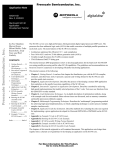
A typical development process is represented in Figure 2.
Introduction to the StarCore™ SC140 Tools: An Approach in Nine Exercises, Rev. 1
2
Freescale Semiconductor
C files
.c, .h
CCSC100
Compiler
IR library
Files .lib
C Compiler
Front End
IR files
.obj
[IR = Intermediate Representation]
Optimizer
icode
Assembler
Assembly files
.sl
Assembly
Files.asm
Assembler
asmsc100
Linker
Object Library
Files .elb
Object Files
.eln
Listing
Files .lst
sc100-ld
Linker
Map
Files .map
“Run-time” Simulator
runsc100
Interactive Simulator
simsc100
Absolute Files
.eld
- Execute Program to completion
- C file I/O capability
- DOS based
Figure 2. StarCore Development Process
Introduction to the StarCore™ SC140 Tools: An Approach in Nine Exercises, Rev. 1
Freescale Semiconductor
3
File I/O Exercise
1
File I/O Exercise
The file I/O exercise shows how to use standard ANSI C I/O features within the current tools suite.
1.
Create a new text file called io.c.
2.
Within the io.c file, write code using the ANSI C printf function to display Welcome to
StarCore SC140 Tools on the screen (remember to include the header file stdio.h),
3.
Compile the file using ccsc100 io.c -o io.eld.
The -o option specifies the output file name (for example, io.eld). If the application does not
compile successfully, correct the reported mistake(s) and recompile the application until a successful
compilation occurs.
4.
Run the executable runsc100 io.eld to display Welcome to StarCore SC140 Tools.
The runsc100 executable is a cycle-accurate run-time simulator. It allows you to run an application to
completion and print out intermediate/final results. You can use this executable for quick code
verification and/or debugging purposes.
Congratulations, you have completed Exercise 1.
Good To Know
The SC140 core supports both Big Endian and Little Endian data
representations. Therefore, the SC140 tools support both modes. By
default, ccsc100 and runsc100 use Little Endian mode.
Big Endian mode can be selected by:
•
specifying the -be option for ccsc100
•
specifying the -e option for runsc100
If the code is built using Big Endian mode, it must be run using Big
Endian mode.
Reminder: (memory storage of a = 0x12345678)
Table 1-1.
2
Big Endian Mode
Little Endian Mode
p:00
1234
p:00
7856
p:02
5678
p:02
3412
Integer and Fractional Arithmetic Exercise
One of the strengths of both the StarCore architecture and the StarCore compiler is the ability to perform both
fractional and integer arithmetic. This exercise presents a reminder about integer and fractional arithmetic
representation and then shows how to use the StarCore compiler fractional intrinsics. Values stored in memory
or registers are interpreted differently depending on the operation performed. For integers, the binary point is
considered to be immediately to the right of the LSB. For the fractional case, the binary point is considered to
be immediately to the right of the MSB. Table 1 illustrates this for 16-bit data values.
Introduction to the StarCore™ SC140 Tools: An Approach in Nine Exercises, Rev. 1
4
Freescale Semiconductor
Integer and Fractional Arithmetic Exercise
Table 1. Interpretation of 16-bit Integer and Fractional Data Values
Hexadecimal
Representation
Integer Value
(decimal)
Fractional value
(decimal)
0100 0000 0000 0000
0x4000
16384
0.5
0001 0000 0000 0000
0x1000
4096
0.125
0000 0000 0000 0000
0x0000
0
0.0
1100 0000 0000 0000
0xC000
-16384
-0.5
1111 0000 0000 0000
0xF000
-4096
-0.125
Binary Representation
2.1 Hardware Support on StarCore
StarCore has a dual instruction set for operations that produce different results depending on whether fractional or
integer arithmetic is used. The instruction set is complementary when an integer or a fractional operation leads to
the same result, regardless of the operation type: for example, an addition. The instruction set is dual (as shown in
Table 2) in two cases, which automatically take care of data alignment, zero filling, and sign extension:
•
When an integer or a fractional operation leads to a different result depending on the operation type:
for example, a multiplication.
•
When data is transferred from/to memory.
Table 2. Fractional and Integer Assembly Language Instructions
Operation
Integer
Fractional
Multiply
impy
mpy
Multiply accumulate
imac
mac
Move
move.b, move.w,
move.2w, move.4w
move.f, move.2f, move.4f
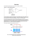
2.2 Compiler Support on StarCore
The StarCore compiler implements fractional arithmetic using built-in intrinsic functions based on integer data
types. Any fractional values or constants must therefore be defined using their integer equivalent. Useful
relationships for deriving these integer representations from the fractional vales are as follows:
•
16-bit Integer Value = Fractional Value × 2 15
•
32-bit Integer Value = Fractional Value × 2 31
•
40-bit Integer Value = Fractional Value × 2 39
The names of the built-in intrinsics conform to the ITU/ETSI basic operation functions. For instance, the L_mac()
intrinsic function is used in the following example (see Figure 3), and a complete list of the intrinsic functions for
fractional arithmetic can be found in the SC100 C/C++ Compiler User’s Manual. The example illustrates how the
Introduction to the StarCore™ SC140 Tools: An Approach in Nine Exercises, Rev. 1
Freescale Semiconductor
5
Integer and Fractional Arithmetic Exercise
instructions are mapped based on the type of the arithmetic required. For integer arithmetic, the compiler generates
integer instructions (for example, imac). For fractional arithmetic, it generates fractional instructions (for example,
mac). Also, move instructions are generated with correct data alignment.
Integer
Fractional
long a;
short b, c;
long a;
short b, c;
a = a + b * c;
a = L_mac(a,b,c);
(Supported by intrinsics)
move.w (r0),d0
move.f (r0),d0
imac d0,d1,d2
mac d0,d1,d2
Figure 3. Integer and Fractional Compiler Support
The energy of a signal, x, represented by Equation 1, is considered:
N–1
y =
∑x
2
(i) ,
Equation 1
i=0
where x(i) is the signal input sample at iteration i, y is the energy of the signal, and N is the signal length.
1.
Open the example file Ex2.c.
Integer Arithmetic
2.
Compile the file using ccsc100 -Ot2 Ex2.c -o Ex2.eld where the -Ot2 option optimizes
the code for time (Force Parallelization).
3.
Run the executable using runsc100.
4.
Recompile the file with the -S option, which stops the compiler after compilation.
5.
Open the generated assembly file Ex2.sl and look at the integer instructions within the loop.
6.
In the box provided here, write down the integer C code and the generated assembly instructions for
the loop. Notice that the first data load is automatically pipelined in the software.
Integer Arithmetic
C code
Generated Assembly code
Fractional Arithmetic
7.
For fractional arithmetic, copy and paste the loop of Ex2.c.
Introduction to the StarCore™ SC140 Tools: An Approach in Nine Exercises, Rev. 1
6
Freescale Semiconductor
Integer and Fractional Arithmetic Exercise
The first loop remains unchanged and performs integer calculation while the second loop is modified
to perform fractional arithmetic.
8.
In the second loop, replace the integer arithmetic operation with the appropriate fractional intrinsic.
Remember, fractional arithmetic is performed using C compiler intrinsics. In this example, the L_mac
intrinsic is used. Its prototype is: long int L_mac(long int, short int, short int).
Therefore, the code modifications should be:
a. Create a new variable “fres” of type “long int.”
b. Replace “res += x[i] * x[i];” with the instruction “fres = L_mac(fres,x[i],x[i]).”
c. Include the file prototype.h, which contains all the intrinsics prototypes.
d. Add another printf statement to print out the fractional result. The result is still a “long int,” so
“%d” should still be used.
9.
Recompile the code with the -S option and look at the generated assembly file Ex2.sl within the
second loop.
10. In the box provided below, write the fractional C code and the generated assembly instructions for that
loop.
Fractional Arithmetic
C code
Generated Assembly code
11. Compare the fractional assembly instructions generated to the assembly integer instructions.
12. Recompile the code without the -S option to produce an executable file.
13. Run the code using runsc100. The variables “res” and “fres” should print to the screen. What is the
algebraic relationship between these two variables?
Congratulations, you have completed Exercise 2.
Good To Know
To perform fractional operations:
•
Intrinsics are used.
•
The variable types remain integer.
•
The header file prototype.h should be included in
the C source file.
All assembly instructions (compiler generated or hand
written) between square brackets [ ] execute in parallel as
a single execution set.
Introduction to the StarCore™ SC140 Tools: An Approach in Nine Exercises, Rev. 1
Freescale Semiconductor
7
Local Versus Global Optimization Exercise
3
Local Versus Global Optimization Exercise
The local versus global optimization exercise shows the difference between two C compiler options: local
optimization (the default) and global optimization. Local optimization compiles each file of the project
individually as represented in Figure 4. Global optimization acts as a global binder that links all the intermediate
representation (IR) files into one file before optimizing the application. Since all the application code information
is available, this approach enables further optimizations beyond those achieved using local optimization alone.
(Compilation takes longer when global optimization is enabled.) Global optimization compilation flow is
represented in Figure 5.
StarCore C Compiler
Local
Optimization
Object library
files .elb
C files
.c, .h
C files
.c, .h
C files
.c, .h
C Compiler
Front End
C Compiler
Front End
C Compiler
Front End
IR Files
.obj
IR Files
.obj
IR Files
.obj
Optimizer
icode
Optimizer
icode
Optimizer
icode
Assembler
asmsc100
Assembler
asmsc100
Assembler
asmsc100
Linker
Figure 4. StarCore Local Optimization
Introduction to the StarCore™ SC140 Tools: An Approach in Nine Exercises, Rev. 1
8
Freescale Semiconductor
Local Versus Global Optimization Exercise
StarCore C Compiler
C Files
.c, .h
C Files
.c, .h
C Files
.c, .h
C Compiler
Front End
C Compiler
Front End
C Compiler
Front End
IR Files
.obj
IR Files
.obj
IR Files
.obj
Global
Optimization
Assembler
asmsc100
Object Library
Files, .elb
Optimizer
icode
Assembler
asmsc100
Assembler
asmsc100
Linker
Figure 5. StarCore Global Optimization
The benefit of Global Optimization is most apparent when several files containing cross references are used, as is
often the case in any sizeable application. In this example, two files are used:
•
the main file called Ex3_main.c
•
a function file called Ex3_prod.c
The main file, Ex3_main.c, calls a routine defined in the function file Ex3_prod.c, as shown in Figure 6.
Introduction to the StarCore™ SC140 Tools: An Approach in Nine Exercises, Rev. 1
Freescale Semiconductor
9
Local Versus Global Optimization Exercise
Ex3_prod.c
Ex3_main.c
...
...
long Prod(short
short a2[])
main()
a1[],
{
{
...
Figure 6. Files for the Local Versus Global Optimization Exercise
1.
Open the two files and understand their functionality.
Local Optimization
2.
Compile the two files:
ccsc100 -Ot2 Ex3_main.c Ex3_prod.c -o Ex3.eld
3.
Run the code: runsc100 -t Ex3.eld.
The -t option for runsc100 enables the cycle count generation. Write the cycle count in the box below:
Local Optimization (Default Mode) Cycle Count
Global Optimization
4.
Compile the files using global optimization:
ccsc100 -Ot2 -Og Ex3_main.c Ex3_prod.c -o Ex3_glo.eld
where -Og is the global optimization option.
5.
Run the code: runsc100 -t Ex3_glo.eld. Write the cycle count in the box below:
Global Optimization (-Og option) Cycle Count
Introduction to the StarCore™ SC140 Tools: An Approach in Nine Exercises, Rev. 1
10
Freescale Semiconductor
Memory Alignment Exercise
To understand how global optimization makes best use of available information, perform these steps:
1.
Recompile the application with -S option (Stop After Compilation) and with the local optimization:
ccsc100 -Ot2 Ex3_main.c Ex3_prod.c -S.
2.
Rename the .sl files as Ex3_main1.sl and Ex3_prod1.sl.
3.
Open the files to see what the compiler has produced.
4.
Enable global optimization: ccsc100 -Ot2 -Og Ex3_main.c Ex3_prod.c -S.
5.
Open Ex3_main.sl to see what the compiler has produced.
Since the compiler has all information on the application, it optimizes the application further than with
local optimization. The compiler avoids calling the function by in-lining the function into the main
code (as shown in Ex3_main.sl). Therefore, it eliminates the cycle overhead associated with
jumping to and returning from the function and passing the parameters to the functions.
Congratulations, you have completed Exercise 3.
Good To Know
4
•
Global optimization requires a longer compilation
time than local optimization.
•
Global optimization further optimizes the application
speed.
Memory Alignment Exercise
The memory alignment exercise shows the usage of wide data moves and the necessary alignments for performing
these moves. The SC140 memory has byte granularity (as represented in Figure 7). Two arithmetic address units
(AAUs) transfer the data from memory to the 4 ALUs (and vice versa) via two 64-bit data buses. Each data bus
allows the transfer of up to eight bytes from memory to the data registers in one cycle (and vice versa).
If the compiler must generate the wide data move instructions available in the StarCore instruction set—such as
move.2w, move.2f, move.4w, and so on—data must be correctly aligned in memory. This is due to the way the
address and data buses operate for multi-byte accesses in the StarCore architecture. The compiler does not generate
wide data move instructions if alignment is not guaranteed. However, if a function is implemented in assembly
language and uses wide data move instructions, you must ensure that the data is aligned on the appropriate
boundary. Otherwise, the wrong data is transferred.
P:0x00
AA
BB
CC DD
EE
FF
AB
BC
8 bytes
P:0x08
01
23
45
89
AB
CD
EF
8 bytes
P:0x10
....
67
Figure 7. Memory Granularity
The following instructions bring more than one byte at a time to the data register:
move.w (Rx), Dn
move.f (Rx), Dn
Transfer one 16-bit word from memory (2 bytes)
Transfer one 16-bit word from memory (2 bytes)
Introduction to the StarCore™ SC140 Tools: An Approach in Nine Exercises, Rev. 1
Freescale Semiconductor
11
Memory Alignment Exercise
move.2w (Rx), Dh
move.2f (Rx), Dh
move.4w (Rx), Dk
move.4f (Rx), Dk
move.2l (Rx), Dh
Transfer two 16-bit words from memory (4 bytes)
Transfer two 16-bit words from memory (4 bytes)
Transfer four 16-bit words from memory (8 bytes)
Transfer four 16-bit words from memory (8 bytes)
Transfer two 32-bit words from memory (8 bytes)
where x spans from 0 to 15 and the data register notations are as follows:
•
Dn represents D0, D1, D2, D3, D4, D5, D6, D7, D8, D9, D10, D11, D12, D13, D14, or D15.
•
Dh represents D0:D1, D2:D3, D4:D5, D6:D7, D8:D9, D10:D11, D12:D13, or D14:D15.
•
Dk represents D0:D1:D2:D3, D4:D5:D6:D7, D8:D9:D10:D11, or D12:D13:D14:D15.
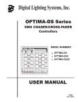
Most processors require operands to be aligned in memory and multiple-operand load/stores to be aligned. For
example, a double operand load requires an even address, and a quad operand load requires a double even address.
These restrictions reduce the complexity of the address generation hardware, particularly for modulo addressing.
For example, let us consider the move.4w (Rx), Dk instruction—more specifically, move.4w
(R0),D0:D1:D2:D3 (four 16-bit words are moved from the memory address of R0 into the data registers D0,
D1, D2, and D3, respectively). The data must align on an 8-byte boundary, so the address contained in R0 should
be a multiple of eight. The examples in Figure 8 further illustrate this point.
.
Aligned
Not Aligned
Bringing one word from memory
move.w (r0),d0 where r0 = 0x0 or 0x2
P:0x00
AA
BB
move.w (r0),d0 where r0 = 0x1 or 0x3
CC DD
P:0x00
Aligned on a 2-byte boundary
Correct Operation: brings either AABB
(if R0 = 0x0) or CCDD (if R0=0x2)
AA
BB
CC DD
Not Aligned on a 2-byte boundary
Erronenous Operation: brings wrong
data in d0
Bringing two words from memory
move.2w (r0),d0:d1 where r0 = 0x0 or 0x4
P:0x00
AA
BB
CC DD
EE
Aligned on a 4-byte boundary
Correct Operation: brings AABB CCDD
(if R0 = 0x0)
move.2w (r0),d0:d1 where r0 = 0x1, 0x2 or 0x3
P:0x00
AA
BB
CC DD EE
Not Aligned on a 4-byte boundary
Erronenous Operation: brings wrong
data in d0:d1
Figure 8. Alignment Considerations
The following instructions require data to be aligned on the specified boundaries:
move.w
move.f
move.2w
(r0),d0
(r0),d0
(r0), d0:d1
2-byte boundary
2-byte boundary
4-byte boundary
Introduction to the StarCore™ SC140 Tools: An Approach in Nine Exercises, Rev. 1
12
Freescale Semiconductor
Memory Alignment Exercise
move.2f
move.4w
move.4f
move.l
move.2l
(r0), d0:d1
(r0),d0:d1:d2:d3
(r0),d0:d1:d2:d3
(r0),d0
(r0),d0:d1
4-byte boundary
8-byte boundary
8-byte boundary
8-byte boundary
8-byte boundary
1.
Open the Ex4.c file, which contains a series of assembly instructions within a C framework using asm
statements. For alternative (and nicer) ways of incorporating assembly code, consult the SC100
C/C++ Compiler User’s Manual.
2.
Look at the assembly instructions to understand the wide data move instructions. Notice that the code
comprises two sections: the first section with aligned data and the second with non-aligned data.
3.
For each instruction, write the result you expect from each section in the boxes provided here (in the
Expected Columns). Array “data[ ]” is of type long int and therefore aligns on a 4-byte boundary.
data:
move #data,r0
0x01 0x231 0x45 0x67 0x89 0xAB 0xCD 0xEF
0xAA 0xBB 0xCC 0xDD 0xEE 0xFF 0x11 0x22
Simulator
Expected
r0 00
0000
0100
move.w (r0),d0
d0
d0
d1
move.2w (r0),d0:d1
d2
d3
d4
move.2f (r0),d2:d3
d5
d6
d7
move.4w (r0),d4:d5:d6:d7
d8
d9
First Code Section
Introduction to the StarCore™ SC140 Tools: An Approach in Nine Exercises, Rev. 1
Freescale Semiconductor
13
Memory Alignment Exercise
data:
0x01 0x23 0x45 0x67 0x89
0xEE 0xFF 0x11 0x22
0xAB
0xCD
0xEF
move.w (r0),d0
r0 00
0000
0xBB
0xCC
0xDD
Simulator
Expected
move #data+2,r0
0xAA
0102
d0
d0
d1
move.2w (r0),d0:d1
d2
d3
move.2f (r0),d2:d3
d4
d5
d6
d7
move.4w (r0),d4:d5:d6:d7
d8
d9
Second Code Section
1.
Compile the Ex4.c file: ccsc100 -be Ex4.c -o Ex4.eld.
The Big Endian (-be) option is used in this exercise to make it easier to read the data in the simulator
memory window. If desired, the Little Endian mode can also be used.
2.
Run the GUI simulator: guisc100. In the simulator command window, type reset d m1 to put the
simulator in Big Endian mode.
3.
Open an assembly window: Windows->Assembly.
4.
Load the file: Load Ex4.eld.
5.
Set a breakpoint on “main” by typing break _main into the command window.
6.
Type go. The code should now be at the start of main.
7.
Open a memory window: Windows->Memory and click OK.
8.
Type data into the Scroll box (of the memory window) to display the contents of the array data[ ]
defined in Ex4.c. Verify that these contents are as expected.
9.
Type next to step through the code.
10. Look at the register contents in the session window and write the values in the Simulator Columns
boxes above for both sections.
Introduction to the StarCore™ SC140 Tools: An Approach in Nine Exercises, Rev. 1
14
Freescale Semiconductor
Split Summation Exercise
Congratulations, you have completed Exercise 4.
.
Good To Know
•
5
Unaligned data accesses lead to erroneous results.You must
consider these issues when developing assembly code.
Split Summation Exercise
The split summation exercise shows how to modify C code using the split summation technique to get better
parallelization. The split summation technique helps to maximize the multiple-ALU loading by performing
arithmetic operations in parallel while requiring little algorithmic or code modifications. To illustrate this
technique, the example performs the the optimization of the energy of a signal calculation already considered in
Exercise 2. The power calculation is represented in Equation 2:
N–1
y =
∑x
2
( i) ,
Equation 2
i=0
where x(i) is the signal input sample at iteration i, y is the power of the signal, and N is the signal length. As
Exercise 2 shows, computing the signal energy directly from Equation 2 results in the use of only one ALU out of
the four with one multiply-accumulate operation performed at each iteration. However, the split summation
technique can load all four ALUs. Equation 2 is expanded as follows:
N–1
y =
∑ x ( i )x( i ) + x ( i + 1 )x ( i + 1 ) + x ( i + 2 )x ( i + 2 ) + x ( i + 3 )x( i + 3 )
Equation 3
i = 0, 4, 8, …
Equation 3 explicitly highlights the four multiply-accumulate operations that can be performed in parallel. Figure
9 highlights where each parallel execution is represented by Group 0, Group 1, and so on. It also shows that the
sample number, i, from one group to the other is incremented by four.
y=
x(i) * x(i) + x(i+1) * x(i+1) + x(i+2) * x(i+2) + x(i+3) * x(i+3)
+
Group 0 (First cycle)
x(i+4) * x(i+4) + x(i+5) * x(i+5) + x(i+6) * x(i+6) + x(i+7) * x(i+7)
Group 1 (Second cycle)
+ ...
Figure 9. Signal Power Calculation Using the Split Summation Technique
1.
Open the Ex5.c file.
2.
Build the code with -Ot2, then run it and notice the output result.
3.
Split the current implementation of the loop (that is, res = L_mac(res, x[i], x[i]);) into
four independent equations as represented in Figure 9.
“Independent” means that the four equations are accumulated into different variables. Therefore,
create four variables for each product. Tip: Watch your index increment.
Introduction to the StarCore™ SC140 Tools: An Approach in Nine Exercises, Rev. 1
Freescale Semiconductor
15
Multi-Sample Exercise
4.
Recompile the file and run it. The output result should be the same as before.
5.
Recompile with the -S option and view the .sl file.
6.
Your code is optimized when the loop is only one cycle and computes four operations at a time.
If the inner loop is equal to one cycle for four operations and the result is still correct, congratulations.
You have completed Exercise 5.
7.
In the box provided below, write the optimized inner loop code:
C Code
Generated Assembly Code
The split summation technique allows full use of all four ALUs, reducing the cycle time by more than 70 percent
relative to use of a single ALU. The 4-ALU technique does not guarantee bit-exactness with the single-ALU
technique because the order of accumulation is different. Using the 4-ALU technique therefore has implications in
applications that are defined by bit-exact standards, such as speech coding standards from ITU, ETSI,TIA/EIA, and
so on.
Good To Know
6
•
The use of four variables removes the accumulation dependency that is required for
parallelism.
•
Bit exact considerations must be understood if this technique is used: overflow/saturation
characteristics may change during split summation.
Multi-Sample Exercise
The multi-sample exercise demonstrates the multisample technique. As the exercise in Section 5 shows, the split
summation technique allows a sum of products operation to be calculated using all four ALUs by evaluating four
intermediate products at a time. However, it does not guarantee bit-exact agreement with serially accumulating
each intermediate product using a single ALU. To ensure bit-exactness, the order of summation must be preserved
by performing each intermediate product/accumulation in turn.Therefore, the intermediate products cannot be
Introduction to the StarCore™ SC140 Tools: An Approach in Nine Exercises, Rev. 1
16
Freescale Semiconductor
Multi-Sample Exercise
evaluated in parallel. Furthermore, the split summation technique may not be suited for the application. Other
techniques can be used where it is possible to evaluate one intermediate product from each of four output sample
calculations in parallel. Consider the FIR filtering operation described by Equation 4:
N–1
y(n ) =
∑ ai x ( n – i ) ,
for 0 ≤ n < L
Equation 4
i=0
A C code implementation of this operation typically resembles the implementation of Ex6.c. To use all four
ALUs, the operations can be grouped as illustrated in the following equation:
y ( n ) = a 0 x( n )
+ a1 x ( n – 1 ) + a2 x ( n – 2 ) + a3x ( n – 3 ) + … + aN – 2 x ( n – N + 2 ) + aN – 1 x ( n – N + 1 )
+ 1 ) = a0 x ( n + 1 ) + a1 x ( n )
+ a 2x ( n – 1 ) + a3 x ( n – 2 ) + … + aN – 2 x ( n – N + 3 ) + a N – 1 x ( n – N + 2 )
+ 2 ) = a0 x ( n + 2 ) + a1 x ( n + 1 ) + a 2x ( n )
+ a3 x ( n – 1 ) + … + aN – 2x ( n – N + 4 ) + aN – 1x ( n – N + 3 )
+ 3 ) = a0 x ( n + 3 ) + a1 x ( n + 2 ) + a 2x ( n + 1 ) + a3x ( n )
Group 0
Group 1
Group 2
Equation 5
+ … + aN – 2 x ( n – N + 5 ) + a N – 1 x ( n – N + 4 )
Group 3
Group N-2
Group N-1
In Equation 5, the products and accumulations within each group are calculated in parallel, but the groups
themselves are evaluated in sequence, thus preserving the order of accumulation, which in turn preserves the bitexactness of Equation 4. Therefore, parallelization is achieved by processing multiple samples in parallel rather
than multiple intermediate products belonging to only one output sample. When one group (for example, Group 2)
is evaluated, only two words of data need to be loaded for the next group (Group 3): a3 and x(n-3). The other values
needed for the calculations in Group 3—x(n-2), x(n-1), and x(n)—should already exist in the DSP registers from
the calculation of Group 2. The result is a reduction in memory bandwidth requirements that increases code
efficiency.
1.
Open the Ex6.c file.
2.
Compile Ex6.c using the -Ot2 option. Run the code and verify that the output is correct.
See the comments in Ex6.c for the correct values of y[].
3.
Recompile Ex6.c using the -Ot2 and -S options. Examine the assembly language file Ex6.sl to see
how the inner loop is compiled.
Intermediate Version: Compromise Between Memory and Speed
4.
Save Ex6.c as Ex6_1.c.
5.
Change the C code of Ex6_1.c according to the following steps:
a. Process the first four samples at a time:
Replace the implementation of “y(n) = ai * x(n)” with the equations defined as Group 0 in Equation 5.
Introduction to the StarCore™ SC140 Tools: An Approach in Nine Exercises, Rev. 1
Freescale Semiconductor
17
Multi-Sample Exercise
b. Replace x(n), x(n+1), x(n+2), x(n+3) with variables (for example, var0, var1, var2, var3,
respectively), as follows:
res0 += a[i]
res1 += a[i]
res2 += a[i]
res3 += a[i]
* var0;
* var1;
* var2;
* var3;
Group 0
This processes the first group (Group 0). To process the remaining groups, Group 1 and so on, the
values from var0, var1, and var2 from Group 0 must be transferred to var1, var2, var3, respectively,
for processing Group 1.
c. Transfer the values in var1, var2, and var3 and load the new sample (x(n-1)) into var0.
6.
Compile the code with the -Ot2 option, and run the code to verify that the correct output values are
obtained.
7.
Recompile Ex6_1.c using the -Ot2 and -S options. The inner loop should be only two cycles long.
If not, return to Step 5.
During each iteration of the loop, the coefficient, a[i], is loaded into a data register. The data value,
x[n-1-i], is loaded into another data register. The values in the other three registers are reused, but
they must first be transferred into the registers where the four MAC instructions expect them. This
transfer results in two clock cycles for every four MAC instructions.
8.
In the box on the following page, write the code for the intermediate version.
C Code
Generated Assembly Code
Further Speed Optimization
The register-to-register transfers can be eliminated by expanding the inner loop so that each group of four MAC
instructions uses the data registers already containing the required data values. This yields faster code, but code
size is greater.
Introduction to the StarCore™ SC140 Tools: An Approach in Nine Exercises, Rev. 1
18
Freescale Semiconductor
Control Code: The True Bit Exercise
1.
Save Ex6_1.c as Ex6_2.c.
2.
In Ex6_2.c, “unroll” the inner loop instructions four times so that the first four groups (Group 0,
Group 1, Group 2, and Group 3) are all processed in the loop. This loop expansion avoids transferring
data. You must reduce the number of loop iterations by a factor of four to compensate for the fact that
the loop is unrolled by a factor of 4.
If your inner loop consumes just four cycles, and your code still produces the correct output, congratulations. You
have completed Exercise 6.
Notice that each group of four MAC operations and two data load operations now requires just one processor cycle,
which is half the time required by the filtering operation and a quarter of the time required by a singleALU DSP device. However, the code size for the inner loop has increased by a significant amount (approximately
four times that of the second implementation), and this must be weighed up against the cycle-count
performance improvements obtained. Table 3 summarizes the main characteristics of the multi-sample technique.
Table 3. Inner Loop Characteristics of Multi-sample and Single-sample Techniques.
Characteristic
Single-sample Algorithm
Multi-sample
Algorithm
N
N/4
Fewer
More
1
4
2N
N/2
Small
Large
Cycle count
Registers used
Sample delay
Number of memory moves (bandwidth)
Code size
7
Control Code: The True Bit Exercise
The True bit exercise shows how the compiler uses the True bit and how you can help the compiler to improve the
performance. The True bit is set/cleared by compare or test instructions. The use of the True bit as a control flag
together with DSP-specific code makes the SC140 very powerful for applications including both control and DSP
code. The True bit can affect conditional branching as well as conditional execution of groups of instructions.
Conditional branching includes:
•
BT/BF: Branch relative if True bit is True/False.
•
BTD:BFD: Branch delayed relative if True bit is True/False.
•
JT/JF: Jump if True bit is True/False.
•
JTD/JFD: Jump delayed if True bit is True/False.
Conditional execution of instructions includes:
•
IFT/IFF: IF True bit is True/False.
•
IFA: IF always, which is unconditionally executed with IFT/IFF.
The conditional execution set combinations are very flexible and are represented in Figure 10, which represents
the maximum number of ALUs (that is, two) and one Arithmetic Address Unit (AAU) per subset. The C compiler
automatically generates the conditional execution set, and some examples are provided to highlight potential code
optimization.
Introduction to the StarCore™ SC140 Tools: An Approach in Nine Exercises, Rev. 1
Freescale Semiconductor
19
Control Code: The True Bit Exercise
IFA
ALU1
ALU2
AAU1
IFT
ALU3
ALU4
AAU2
IFT
ALU1
ALU2
AAU1
IFF
ALU3
ALU4
AAU2
IFA
ALU1
ALU2
AAU1
IFF
ALU3
ALU4
AAU2
Figure 10. Control Instructions Using the True Bit
1.
Open the example Ex7.c file.
2.
Understand the conditional test in the code.
3.
Compile the project with the -Ot2 and -S options.
4.
Open the generated assembly file Ex7.sl, and look at the conditional instructions within the loop.
5.
In the box provided here, write down how many execution sets are within the loop:
Optimized for Time
Optimized for Space
6.
Recompile using the compiler optimization option for code size (-Os option).
7.
Open the generated assembly file Ex7.sl, and look at the conditional instructions within the loop.
Write down how many execution sets are within the loop in the box.
8.
Save Ex7.c as Ex7_1.c.
9.
Modify the program to obtain two cycles within the loop. Tip: consider using a temporary variable for
both storing the immediate value of the array1 and the conditional test.
10. Compile the code using the -Ot2 option.
11. Open the file Ex7_1.sl.
12. If you have obtained two cycles for the inner loop, congratulations. If you have not, please try again.
13. In the following box, write the optimized C code.
Introduction to the StarCore™ SC140 Tools: An Approach in Nine Exercises, Rev. 1
20
Freescale Semiconductor
Calling an Assembly Routine From C Exercise
C Code
8
Generated Assembly Code
Calling an Assembly Routine From C Exercise
Practical DSP application commonly use a mixture of C and assembly language. This exercise shows how an
assembly language function can be called from C code. The code for this exercise is contained in two files: Ex8.c
and addvecs.asm. The C code in Ex8.c calls the assembly language function, addvecs(), in file
addvecs.asm, to add two vectors together and return the sum of all the elements of the resultant vector. The
prototype for addvecs() is as follows:
short add_vecs
(
short x[],
short y[],
short z[],
short length
);
/*
/*
/*
/*
Input vector
Input vector
Output vector
Length of vectors
*/
*/
*/
*/
Four parameters are passed to addvecs(). The first three are pointers to arrays and are therefore 32-bit values
(addresses are 32-bits in StarCore). The fourth parameter is the length of the vectors and is a 16-bit value. The
mechanism by which parameters are passed is specified in the application binary interface (ABI). Generally
speaking, this ABI specifies the following calling convention:
•
The first parameter is passed in d0 if it is a numeric scalar or in r0 if it is an address.
•
The second parameter is passed in d1 if it is a numeric scalar or in r1 if it is an address.
•
Subsequent parameters are pushed onto the stack.
•
The return value (if any) is passed back to the calling function in d0 if it is a numeric scalar or in r0 if
it is an address.
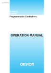
For simple functions with two parameters or fewer, the stack is not used to pass parameters, and it may be possible
to write the entire assembly language function without explicitly using the stack at all. In general, however, the
stack is used to pass parameters into the function and to store local variables. Its contents are as shown in Figure
11. Just prior to the function call, parameters 3, 4, 5, and so on are pushed onto the stack (in reverse order), and
parameters 1 and 2 are stored in d0/r0 and d1/r1, as described previously. The function is then called, and the return
Introduction to the StarCore™ SC140 Tools: An Approach in Nine Exercises, Rev. 1
Freescale Semiconductor
21
Calling an Assembly Routine From C Exercise
address and status register contents are pushed onto the stack by the jsr or bsr instruction. If the called function
modifies register d6, d7, r6, or r7, it should first save them on the stack and then restore them before returning. All
other registers are free for use without saving or restoring them. The calling function must save these registers if it
needs their values to be preserved. On function exit, the status register contents and return address are popped from
the stack (by the rts instruction), and the calling function deallocates the stack space used to pass parameters 3, 4,
5, and so on.
High Address
SP
Local
Variables
(if any)
SP
(Current)
Saved
Registers
SP
Return
Address
Parameters
3, 4, 5, ...
SP
¹
²
Return
Address
Parameters
3, 4, 5, ...
SP
Return
Address
SP
Parameters
3, 4, 5, ...
Parameters
3, 4, 5, ...
¼
½
³
SP
ª
Low Address
¹ Prior to function call
² On entry to function
³ During function execution
¼ Prior to exit from function
½ On return from function
ª Calling function deallocates parameters on stack
Figure 11. Typical Stack Contents During Function Execution
Therefore, for the function addvecs(), parameters x[], and y[] are passed in r0 and r1, while z[] and M are passed on
the stack.
1.
Open the Ex8.c and addvecs.asm files, and familiarize yourself with the code.
2.
In addvecs.asm are two constants, Z_OFFSET and M_OFFSET, whose values are not set and which
are represented by question marks (???). These offsets pull z[] and M from the stack. Find the lines of
code that perform this task.
3.
Before the code can be built, you must assign values to Z_OFFSET and M_OFFSET. To help you to
do this, Figure 12 shows the stack on entry to addvecs().
Introduction to the StarCore™ SC140 Tools: An Approach in Nine Exercises, Rev. 1
22
Freescale Semiconductor
Calling an Assembly Routine From C Exercise
SP
On function entry
SP
Prior to function call
4
Status Register
4
Return Address
4
&z[0]
2
2
M
}
}
Pushed on stack by jsr/bsr instruction
Parameters pushed onto stack prior to jsr/bsr
Figure 12. Stack Contents on Entry to advecs()
4.
In the box provided here, write what you think the offsets should be:
Z_OFFSET
M_OFFSET
5.
Modify the addvecs.asm file to incorporate your offset values.
6.
Build the code.
7.
Run the code: runsc100 Ex8.eld.
8.
The following output should be displayed:
z = [3, 5, 7, 9, 11, 13, 15, 17]
sum = 80
9.
If the above output is displayed, your offset values are correct.
10. Rebuild the code, this time with the -S option.
11. Open the generated assembly file Ex8.sl, and find the call to addvecs().
12. Find the instructions that put z[] and M onto the stack just prior to the function call. Write the offsets in
the box provided here:
Z_OFFSET
M_OFFSET
13. Are the offsets used in Ex8.c the same as the offsets used in addvecs.asm? If not, can you explain
why?
Congratulations, you have completed Exercise 8.
Introduction to the StarCore™ SC140 Tools: An Approach in Nine Exercises, Rev. 1
Freescale Semiconductor
23
The Challenge
Good To Know
The stack pointer must always be a multiple of 8. It is illegal to
increment it by a non-multiple of 8.
9
The Challenge
This section presents you with a challenge involving an example that implements a complex scalar product. The
objective of this session is to optimize the code from Ex9.c for speed and obtain the minimum number of cycles.
1.
Put into practice the techniques previously explained to optimize Ex9.c.
The original number of cycles in the inner loop is:
Original (Inner loop)
So far, after having modified the code, your best result is:
Your Best (Inner loop)
The optimized C code result is:
Target (Inner loop)
1 cycle with ALUs and AAUs 100 percent used
If your best result is within 10 percent of the target result, congratulations. You have completed all the exercises
and the challenge as well.
Introduction to the StarCore™ SC140 Tools: An Approach in Nine Exercises, Rev. 1
24
Freescale Semiconductor
Solutions to Exercises
10 Solutions to Exercises
Exercise 1:
/*****************************************************************************
*
Freescale Semiconductor, Inc.
*
COPYRIGHT 1999
*******************************************************************************
*
INTRODUCTION TO THE SC140 TOOLS
*******************************************************************************/
#include <stdio.h>
main()
{
printf(“Welcome to StarCore SC140 Tools\n”);
}
Exercise 2:
/*****************************************************************************
*
Freescale Semiconductor, Inc.
*
COPYRIGHT 1999 Freescale Semiconductor, Inc.
*******************************************************************************
*
INTRODUCTION TO THE SC140 TOOLS
*******************************************************************************/
#include <stdio.h>
#include <prototype.h>
short x[12] = {0,1,2,3,4,5,6,7,8,9,10,11};
main()
{
short i;
long res=0;
long fres=0;
for(i=0;i<12;i++)
{
res += x[i] * x[i];
}
for(i=0;i<12;i++)
{
fres = L_mac(fres,x[i],x[i]);
}
printf("The integer result is:
%d (0x%x)\n",res,res);
printf("The fractional result is:
%d (0x%x)\n",fres,fres);
}
Introduction to the StarCore™ SC140 Tools: An Approach in Nine Exercises, Rev. 1
Freescale Semiconductor
25
Solutions to Exercises
Exercise 3:
No code modification is required.
Exercise 4:
data:
0x01 0x23 0x45 0x67 0x89 0xAB 0xCD 0xEF
0xAA 0xBB 0xCC 0xDD 0xEE 0xFF 0x11 0x22
Expected
Simulator
move #data,r0
r0
move.w (r0),d0
d0
00
0000
0123
00
0000
0123
d0
00
0000
0123
00
0000
0123
d1
00
0000
4567
00
0000
4567
d2
00
0123
0000
00
0123
0000
d3
00
4567
0000
00
4567
0000
d4 00
0000
0123
00
0000
0123
00
0000
4567
00
0000
4567
d6 FF
FFFF
89AB
FF
FFFF
89AB
d7 FF
FFFF
CDEF
FF
FFFF
CDEF
d8
00
0123
4567
00
0123
4567
d9
FF
89AB
CDEF
FF
89AB
CDEF
move.2w (r0),d0:d1
move.2f (r0),d2:d3
move.4w (r0),d4:d5:d6:d7
d5
Aligned
Introduction to the StarCore™ SC140 Tools: An Approach in Nine Exercises, Rev. 1
26
Freescale Semiconductor
Solutions to Exercises
data:
0x01 0x23 0x45 0x67 0x89 0xAB 0xCD 0xEF
0xAA 0xBB 0xCC 0xDD 0xEE 0xFF 0x11 0x22
Simulator
Expected
move #data+2,r0
r0
d0 00
move.w (r0),d0
4567
00
0000
4567
d0 00 0000
d1 FF FFFF
4567
00
0000
0123
89AB
00
0000
4567
d2 00
d3 FF
4567
0000
00
0123
0000
89AB
0000
00
4567
0000
d4 00
0000
4567
00
0000
0123
d5
FF
FFFF
89AB
00
0000
4567
d6 FF
d7 FF
FFFF
CDEF
FF
FFFF
89AB
FFFF
AABB
FF
FFFF
CDEF
d8 00
d9 FF
4567
89AB
00
0123
4567
CDEF
AABB
FF
89AB
CDEF
0000
move.2w (r0),d0:d1
move.2f (r0),d2:d3
move.4w (r0),d4:d5:d6:d7
Aligned/Not Aligned
The crosses indicate that the results provided by the simulator are not-aligned operations. If this is not taken into
account, unpredictable results can occur when migrating to the hardware (which requires aligned data).
Introduction to the StarCore™ SC140 Tools: An Approach in Nine Exercises, Rev. 1
Freescale Semiconductor
27
Solutions to Exercises
Exercise 5:
/*****************************************************************************
*
Freescale Semiconductor, Inc.
*
COPYRIGHT 1999 Freescale Semiconductor, Inc.
*******************************************************************************
*
INTRODUCTION TO THE SC140 TOOLS
*******************************************************************************/
/* Split Summation Technique Exercise */
#include <stdio.h>
#include <prototype.h>
short x[12] = {0,1,2,3,4,5,6,7,8,9,10,11};
main()
{
short i;
long res1=0, res2=0, res3=0, res4=0;
for(i=0;i<12;i+=4)
{
res1 = L_mac(res1, x[i], x[i]);
res2 = L_mac(res2, x[i+1], x[i+1]);
res3 = L_mac(res3, x[i+2], x[i+2]);
res4 = L_mac(res4, x[i+3], x[i+3]);
}
/* To optimise the code further break the following dependency */
/* res1 = res1 + res2 + res3 + res4; */
/* into */
res1 = res1 + res2;
res3 = res3 + res4;
res1 = res1 + res3;
printf("Result = %d
(0x%x)\n", res1,res1);
}
Introduction to the StarCore™ SC140 Tools: An Approach in Nine Exercises, Rev. 1
28
Freescale Semiconductor
Solutions to Exercises
Exercise 6:
Intermediate version: Compromise between Memory and Speed
/*****************************************************************************
*
Freescale Semiconductor, Inc.
*
COPYRIGHT 1999 Freescale Semiconductor, Inc.
*******************************************************************************
*
INTRODUCTION TO THE SC140 TOOLS
*******************************************************************************/
/* Multi-sample technique Exercise on an FIR Filter */
#include <stdio.h>
#include <prototype.h>
short a[12]={0x1000,0x2000,0x3000,0x4000,0x5000,0x6000,
0x7000,0x8000,0x9000,0xA000,0xB000,0xC000};
short input[32+11]={0,0,0,0,0,0,0,0,0,0,0, /* zero-padding */
0x0100,0x0200,0x0300,0x0400,0x0500,0x0600,0x0700,0x0800,
0x0900,0x0A00,0x0B00,0x0C00,0x0D00,0x0E00,0x0F00,0x1000,
0x1100,0x1200,0x1300,0x1400,0x1500,0x1600,0x1700,0x1800,
0x1900,0x1A00,0x1B00,0x1C00,0x1D00,0x1E00,0x1F00,0x2000};
short y[32];
/**********************************************************************
*** For reference, the following output should be observed after
***
*** running the code.
***
**********************************************************************
*
*
* y[0] = 0x0020
*
* y[1] = 0x0080
*
* y[2] = 0x0140
*
* y[3] = 0x0280
*
* y[4] = 0x0460
*
* y[5] = 0x0700
*
* y[6] = 0x0A80
*
* y[7] = 0x0D00
*
* y[8] = 0x0EA0
*
* y[9] = 0x0F80
*
* y[10] = 0x0FC0
*
* y[11] = 0x0F80
*
* y[12] = 0x0F40
*
* y[13] = 0x0F00
*
* y[14] = 0x0EC0
*
* y[15] = 0x0E80
*
* y[16] = 0x0E40
*
* y[17] = 0x0E00
*
* y[18] = 0x0DC0
*
* y[19] = 0x0D80
*
* y[20] = 0x0D40
*
* y[21] = 0x0D00
*
Introduction to the StarCore™ SC140 Tools: An Approach in Nine Exercises, Rev. 1
Freescale Semiconductor
29
Solutions to Exercises
* y[22] = 0x0CC0
*
* y[23] = 0x0C80
*
* y[24] = 0x0C40
*
* y[25] = 0x0C00
*
* y[26] = 0x0BC0
*
* y[27] = 0x0B80
*
* y[28] = 0x0B40
*
* y[29] = 0x0B00
*
* y[30] = 0x0AC0
*
* y[31] = 0x0A80
*
**********************************************************************/
main()
{
long res0, res1, res2, res3;
short var0, var1, var2, var3;
short n, i, *x_ptr;
x_ptr = &input[14];
for(n=0;
{
res0 =
res1 =
res2 =
res3 =
var3
var2
var1
var0
=
=
=
=
/* x_ptr points to input[11], which is x[3] */
n<32; n+=4)
0;
0;
0;
0;
*x_ptr--;
*x_ptr--;
*x_ptr--;
*x_ptr--;
/*
/*
/*
/*
var3
var3
var3
var3
=
=
=
=
x[n+3]
x[n+2]
x[n+1]
x[n]
*/
*/
*/
*/
/*** x_ptr now points to x[n-1] ***/
for(i=0;
{
res0 =
res1 =
res2 =
res3 =
var3
var2
var1
var0
=
=
=
=
i<12; i++)
L_mac(res0,
L_mac(res1,
L_mac(res2,
L_mac(res3,
var2;
var1;
var0;
*x_ptr--;
a[i],
a[i],
a[i],
a[i],
var0);
var1);
var2);
var3);
/* var0 = x[n-i-1] */
}
/*** Truncate results and store in y[] ***/
y[n]
= extract_h(res0);
y[n+1] = extract_h(res1);
y[n+2] = extract_h(res2);
Introduction to the StarCore™ SC140 Tools: An Approach in Nine Exercises, Rev. 1
30
Freescale Semiconductor
Solutions to Exercises
y[n+3] = extract_h(res3);
x_ptr += 20;
/* Increment pointer by 20 to point to x[n+7]
for next iteration */
}
/*** Print results, y[] ***/
for (n=0; n<32; n++)
{
printf ("y[%d] = 0x%04hX\n", n, y[n]);
}
}
Further Optimizing the Speed
/*****************************************************************************
*
Freescale Semiconductor, Inc.
*
COPYRIGHT 1999 Freescale Semiconductor, Inc.
*******************************************************************************
*
INTRODUCTION TO THE SC140 TOOLS
*******************************************************************************/
/* Multi-sample technique Exercise on an FIR Filter */
#include <stdio.h>
#include <prototype.h>
short a[12]={0x1000,0x2000,0x3000,0x4000,0x5000,0x6000,
0x7000,0x8000,0x9000,0xA000,0xB000,0xC000};
short input[32+11]={0,0,0,0,0,0,0,0,0,0,0, /* zero-padding */
0x0100,0x0200,0x0300,0x0400,0x0500,0x0600,0x0700,0x0800,
0x0900,0x0A00,0x0B00,0x0C00,0x0D00,0x0E00,0x0F00,0x1000,
0x1100,0x1200,0x1300,0x1400,0x1500,0x1600,0x1700,0x1800,
0x1900,0x1A00,0x1B00,0x1C00,0x1D00,0x1E00,0x1F00,0x2000};
short y[32];
/**********************************************************************
*** For reference, the following output should be observed after
***
*** running the code.
***
**********************************************************************
*
*
* y[0] = 0x0020
*
* y[1] = 0x0080
*
* y[2] = 0x0140
*
* y[3] = 0x0280
*
* y[4] = 0x0460
*
* y[5] = 0x0700
*
* y[6] = 0x0A80
*
* y[7] = 0x0D00
*
* y[8] = 0x0EA0
*
* y[9] = 0x0F80
*
* y[10] = 0x0FC0
*
Introduction to the StarCore™ SC140 Tools: An Approach in Nine Exercises, Rev. 1
Freescale Semiconductor
31
Solutions to Exercises
* y[11] = 0x0F80
*
* y[12] = 0x0F40
*
* y[13] = 0x0F00
*
* y[14] = 0x0EC0
*
* y[15] = 0x0E80
*
* y[16] = 0x0E40
*
* y[17] = 0x0E00
*
* y[18] = 0x0DC0
*
* y[19] = 0x0D80
*
* y[20] = 0x0D40
*
* y[21] = 0x0D00
*
* y[22] = 0x0CC0
*
* y[23] = 0x0C80
*
* y[24] = 0x0C40
*
* y[25] = 0x0C00
*
* y[26] = 0x0BC0
*
* y[27] = 0x0B80
*
* y[28] = 0x0B40
*
* y[29] = 0x0B00
*
* y[30] = 0x0AC0
*
* y[31] = 0x0A80
*
**********************************************************************/
main()
{
long res0, res1, res2, res3;
short var0, var1, var2, var3;
short n, i, *x_ptr;
x_ptr = &input[14]; /* x_ptr points to input[14], which is x[3] */
for(n=0; n<32; n+=4)
{
res0 = 0;
res1 = 0;
res2 = 0;
res3 = 0;
var3
var2
var1
var0
=
=
=
=
*x_ptr--;
*x_ptr--;
*x_ptr--;
*x_ptr--;
/*
/*
/*
/*
var3
var3
var3
var3
=
=
=
=
x[n+3]
x[n+2]
x[n+1]
x[n]
*/
*/
*/
*/
/*** x_ptr now points to x[n-1] ***/
for(i=0; i<12; i+=4)
{
res0 = L_mac(res0, a[i], var0);
res1 = L_mac(res1, a[i], var1);
res2 = L_mac(res2, a[i], var2);
res3 = L_mac(res3, a[i], var3);
var3 = *x_ptr--; /* var3 = x[n-i-1] */
Introduction to the StarCore™ SC140 Tools: An Approach in Nine Exercises, Rev. 1
32
Freescale Semiconductor
Solutions to Exercises
res0
res1
res2
res3
var2
=
=
=
=
=
L_mac(res0, a[i+1],
L_mac(res1, a[i+1],
L_mac(res2, a[i+1],
L_mac(res3, a[i+1],
*x_ptr--; /* var2 =
var3);
var0);
var1);
var2);
x[n-i-2] */
res0
res1
res2
res3
var1
=
=
=
=
=
L_mac(res0, a[i+2],
L_mac(res1, a[i+2],
L_mac(res2, a[i+2],
L_mac(res3, a[i+2],
*x_ptr--; /* var1 =
var2);
var3);
var0);
var1);
x[n-i-3] */
res0
res1
res2
res3
var0
=
=
=
=
=
L_mac(res0, a[i+3],
L_mac(res1, a[i+3],
L_mac(res2, a[i+3],
L_mac(res3, a[i+3],
*x_ptr--; /* var0 =
var1);
var2);
var3);
var0);
x[n-i-4] */
}
/*** Truncate results and store in y[] ***/
y[n]
= extract_h(res0);
y[n+1] = extract_h(res1);
y[n+2] = extract_h(res2);
y[n+3] = extract_h(res3);
x_ptr += 20;
/* Increment pointer by 20 to point to x[n+7]
for next iteration */
}
/*** Print results, y[] ***/
for (n=0; n<32; n++)
{
printf ("y[%d] = 0x%04hX\n", n, y[n]);
}
}
Exercise 7:
/*****************************************************************************
*
Freescale Semiconductor, Inc.
*
COPYRIGHT 1999 Freescale Semiconductor, Inc.
*******************************************************************************
*
INTRODUCTION TO THE SC140 TOOLS
*******************************************************************************/
short array1[10]={1,-1,-1,-2,2,-2,2,-2,3,-3};
short array2[10];
main()
{
short i;
short *array2_ptr;
short tmp;
array2_ptr = &array2[0];
Introduction to the StarCore™ SC140 Tools: An Approach in Nine Exercises, Rev. 1
Freescale Semiconductor
33
Solutions to Exercises
for(i=0;i<10;i++)
{
tmp = array1[i];
if( tmp < 0)
{
tmp = -tmp;
}
*array2_ptr++ = tmp;
}
}
Introduction to the StarCore™ SC140 Tools: An Approach in Nine Exercises, Rev. 1
34
Freescale Semiconductor
Solutions to Exercises
Exercise 8:
Z_OFFSET
M_OFFSET
equ
equ
-12
-14
Exercise 9:
/*****************************************************************************
*
Freescale Semiconductor, Inc.
*
COPYRIGHT 1999 Freescale Semiconductor, Inc.
*******************************************************************************
*
INTRODUCTION TO THE SC140 TOOLS
*******************************************************************************/
#include <prototype.h>
#define DATA_LENGTH 6
Word16 y[2];
Word16 a[12]={0x0200, 0x0400, 0x0200, 0x0400,
0x0200, 0x0400, 0x0200, 0x0400,
0x0200, 0x0400, 0x0200, 0x0400};
Word16 b[12] = {0x0100, 0x0800, 0x1000, 0x2000,
0x1000, 0x0800, 0x0200, 0x0100,
0x1000, 0x0800, 0x0200, 0x0100};
void main()
{
Word16 i;
Word32 L_Re1, L_Re2, L_Im1, L_Im2;
L_Re1 = L_Re2 = L_Im1 = L_Im2 = 0;
for(i=0; i<2*DATA_LENGTH; i+=2)
{
L_Re1 = L_mac(L_Re1, a[i], b[i]);
L_Im1 = L_mac(L_Im1, a[i], b[i+1]);
L_Im2 = L_mac(L_Im2, a[i+1], b[i]);
L_Re2 = L_mac(L_Re2, a[i+1], b[i+1]);
}
y[0] = round(L_Re1 - L_Re2);
y[1] = round(L_Im1 + L_Im2);
}
Introduction to the StarCore™ SC140 Tools: An Approach in Nine Exercises, Rev. 1
Freescale Semiconductor
35
How to Reach Us:
Home Page:
www.freescale.com
E-mail:
[email protected]
USA/Europe or Locations not listed:
Freescale Semiconductor
Technical Information Center, CH370
1300 N. Alma School Road
Chandler, Arizona 85224
+1-800-521-6274 or +1-480-768-2130
[email protected]
Europe, Middle East, and Africa:
Freescale Halbleiter Deutschland GMBH
Technical Information Center
Schatzbogen 7
81829 München, Germany
+44 1296 380 456 (English)
+46 8 52200080 (English)
+49 89 92103 559 (German)
+33 1 69 35 48 48 (French)
[email protected]
Japan:
Freescale Semiconductor Japan Ltd.
Headquarters
ARCO Tower 15F
1-8-1, Shimo-Meguro, Meguro-ku,
Tokyo 153-0064, Japan
0120 191014 or +81 3 5437 9125
[email protected]
Asia/Pacific:
Freescale Semiconductor Hong Kong Ltd.
Technical Information Center
2 Dai King Street
Tai Po Industrial Estate
Tai Po, N.T. Hong Kong
+800 2666 8080
For Literature Requests Only:
Freescale Semiconductor Literature Distribution Center
P.O. Box 5405
Denver, Colorado 80217
1-800-441-2447 or 303-675-2140
Fax: 303-675-2150
[email protected]
AN2009
Rev. 1
11/2004
Information in this document is provided solely to enable system and software implementers to
use Freescale Semiconductor products. There are no express or implied copyright licenses
granted hereunder to design or fabricate any integrated circuits or integrated circuits based on
the information in this document.
Freescale Semiconductor reserves the right to make changes without further notice to any
products herein. Freescale Semiconductor makes no warranty, representation or guarantee
regarding the suitability of its products for any particular purpose, nor does Freescale
Semiconductor assume any liability arising out of the application or use of any product or
circuit, and specifically disclaims any and all liability, including without limitation consequential
or incidental damages. “Typical” parameters which may be provided in Freescale
Semiconductor data sheets and/or specifications can and do vary in different applications and
actual performance may vary over time. All operating parameters, including “Typicals” must be
validated for each customer application by customer’s technical experts. Freescale
Semiconductor does not convey any license under its patent rights nor the rights of others.
Freescale Semiconductor products are not designed, intended, or authorized for use as
components in systems intended for surgical implant into the body, or other applications
intended to support or sustain life, or for any other application in which the failure of the
Freescale Semiconductor product could create a situation where personal injury or death may
occur. Should Buyer purchase or use Freescale Semiconductor products for any such
unintended or unauthorized application, Buyer shall indemnify and hold Freescale
Semiconductor and its officers, employees, subsidiaries, affiliates, and distributors harmless
against all claims, costs, damages, and expenses, and reasonable attorney fees arising out of,
directly or indirectly, any claim of personal injury or death associated with such unintended or
unauthorized use, even if such claim alleges that Freescale Semiconductor was negligent
regarding the design or manufacture of the part.
Freescale™ and the Freescale logo are trademarks of Freescale Semiconductor, Inc. StarCore
is a trademark of StarCore LLC. All other product or service names are the property of their
respective owners.
© Freescale Semiconductor, Inc. 2004.