1
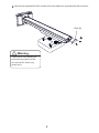
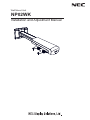
Wall Mount Unit
NP02WK
Installation and Adjustment Manual
Wall Mount Unit
NP02WK Installation and Adjustment Manual
Thank you for your purchase of this NEC wall mount unit.
Please read this installation and adjustment manual carefully to ensure proper use.
The Wall Mount Unit NP02WK is exclusively for Projector NP-M260XS/M300XS/M350XS/
M260WS/M300WS and cannot be used for other projectors.
Special skills are required to install the pojector. This work
should never be performed by the customer.
To the Dealer and Installer
To ensure customer safety, we ask that the installation work
be started after careful attention is paid to the strength of the
mounting location to ensure it will withstand the weight of the
projector and mounting hardware.
CONTENTS
Please heed the following
........................................................1
Preparation...........................................................................4
Packaged Parts
............................................................. 4
Names of Parts
.............................................................. 5
Dimensions of Parts
....................................................... 6
7
Mounting the Projector ............................................................
10
Adjusting the Projection Position ............................................
Specifications ........................................................................13
1
Please heed the following
Symbol
In this “Installation and Adjustment Manual”, to ensure the safe and proper use of the product,
prevent harm to yourself and others and damage to property, various symbols are used. The
symbols and meanings are as follows. Please read this manual after ensuring the contents are well
understood.
Warning
Improper handling and ignoring this indication may result in
bodily harm such as death, serious injury and so on.
Caution
Improper handling and ignoring this indication may result in
bodily injury and damage to surrounding contents.
Examples of symbols:
Symbol alerts you to cautions (including warnings)
Concrete cautions are specified in figures.
Symbol expresses prohibited actions
Concrete prohibitions are specified in figures.
Symbol expresses compulsory actions.
Concrete instructions are specified in figures.
Warning
• When installing the projector and adjusting the projection position, be sure to do so
as explained in this manual. The projector may fall and cause injury if installed and
adjusted improperly.
• To prevent the projector from falling, install it in a location and fasten it so as to ensure
sufficient strength to support the combined weight (about 12.7kg) of the projector (about
6.5kg), the wall mount unit (about 6.2kg) and so on for an extended period as well as
to withstand earthquakes. Insufficient strength or fastening may result in the projector
falling and causing injury.
Be sure to observe the following precautions:
* Use M6 (1/4 inch) for the wall fixation bolts and screws for the wall adapter.
* Use an outlet for the power source of the projector. Do not directly connect to the
lamp line because this is dangerous. Also, use an accessible outlet so that you can
connect and disconnect the power plug.
• Mounting on a wooden wall
Ensure the load is mounted on a pillar or robust constructional material. If the strength
of the constructional material and so on is insufficient, please reinforce it. Do not mount
on wall finishing material, furring strip and so on.
• Mounting on a concrete wall
Use a commercial anchor bolt M6 (1/4 inch), anchor nuts and similar, which will bear
the load of the projector.
2
Warning
• Do not install in places subject to constant vibration. Extended vibration may cause
loosening of the screws and result in the Wall Mount Unit and projector falling and
causing injury. Also, it may cause breakdown of the projector.
• To ensure safety, be sure to tighten the bolts, screws and adjusting knobs securely
Failure to do so may result in the projector falling and causing injury.
• Do not modify any parts.Doing so may result in the projector and the Wall Mount Unit
falling and causing injury.
• Do not use broken parts. Doing so may result in the projector and the Wall Mount Unit
falling and causing injury. If a part should break, consult your dealer.
• Do not look into the mirror when the projector is turned on. Doing so could damage
your eyesight.
• Do not hang from the projector and the Wall Mount Unit. Doing so may result in the
projector and the Wall Mount Unit falling and causing injury. Be especially careful of
children.
• Do not use adhesivefor the locking screws, lubricant agent, oil andso on for the wall
adapter. Doing so may cause the material of the wall adapter to deteriorate and result
in the projector falling and causing injury.
Caution
• Do not obstruct the projector’s ventilation holes. Doing so will prevent the dissipation
ways:
installing the projector in a place such as wall and so on where ventilation is poor,
covering it, etc.
• Do not install the projector in front of the outlets of an air conditioner or heater or in a
• Do not install the projector in humid or dusty places or those exposed to greasy
Please:
Dirt will adhere to the optical parts such as mirrors, which will cause image quality to
deteriorate.
• Avoid places in which the screen is exposed to direct sunlight or illuminated light.
view.
• Avoid locations exposed to particularly high or low temperatures.
Doing so may result in breakdown. (For the ambient operating temperature, see the user’s
manual included with the projector.)
3
Preparation
Packaged Parts
Please check the packaged items.
Cover (A, B):2 pairs
Wall adapter:1
Arm cover:1
Arm:1
Plate (B):1
M4×20 screws:4
M3.5×9.4 screws:2
Hex wrench:1
Projector adapter:1
Optional
Installation and Adjustment
Manual:1
Wall plate:1 *1
M5 screws:4 *2
*1, *2:To be used when mounting the wall adapter in the North America region.
4
Names of Parts
Arm cover
Elongate hole for screw (or bolt)
(4 parts)
Covers (A, B)
Plate (A)
•
Arm fixation screw
Grooves for wiring
Arm
Tilt adjust knobs (4 parts)
Wall adapter
Cover (B, A)
Central axis
Projector
adapter
Plate (B)
Horizontal fixation nut
•
•
Projector fixation
plate
Vertical adjust/
Arm fixation knobs
5
Horizontal adjust screws
Dimensions of Parts:
(unit: mm)
The dimensions of the positions of the wall fixation screws (bolts) of the wall adapter are
described
280
Central axis
189
490
850
Projector posterior surface
142
100
90-190
100
189
219
The center of the wall adapter
(central axis)
883 (minimum) -1263 (maximum)
Projector bottom surface
(including the legs)
100
142
6
100
Mounting the Projector
Preparations
1. Determine the installation location of the screen, and accordingly decide
the installation position of the wall mount unit.
Refer to the section "Installation" in the user’s manual included with the projector for more
information.
• Installation for slanted projection is not possible. Determine the position for frontprojection.
2. Make sure that all conditions described in the section "Heed the Following"
on page 2 of this manual are met.
• Because the M260XS/M300XS/M350XS/M260WS/M300WS have a large optical axis
elevation angle, a slight shift in projection distance will have a large effect on the screen
size and position. If the projector angle is off, image distortion will increase.
1
2
Align the projector adapter with the holes on the bottom of the projector and securely attach
the adapter with the four supplied screws (M4x20).
Loosen the vertical adjust/arm fixation knobs of the projector adapter.
Caution Do not try to attach the projector adapter without the foam packing spacers in
place. Otherwise the mirror section may be subject to excessive force, which can
lead to a shift in the pr ojected image and cause serious damage.
1
2
Vertical adjust/arm fixation knobs
Warning
If screws other than the supplied ones
are used, the projector may be seriously
damaged, or the projector may fall and
cause injury. Be sure to use only the
supplied screws.
2. Attach the wall adapter to the structural material of the wall.
To ensure a projected image without distortion, the center of the wall adapter and the center of
the screen should be aligned on a straight axis.
• The wall adapter has a top/bottom orientation. Be sure to attach it with correct orientation.
Caution If the wall adapter is mounted with reversed top/bottom orientation, correct
installation is not possible.
• The wall adapter can be adjusted horizontally over a range of ±50mm.
Warning
Use only M6 (1/4 inch) screws
or bolts (4 locations) to fix the wall
adapter. If screws or bolts other than M6
are used, the projector may fall and
cause injury.
Side with cutouts facing up
Side without cutouts facing down
7
3. Attach the arm to the wall adapter
.
3
Thread the cables through the arm plates and the arm.
Loosen the arm fixation screws (top and bottom) with the supplied hex wrench.
Insert the arm plate (A) into the wall adapter from the top and tighten the screws (top and
bottom) near the center of the elongated hole.
* The covers (A) and (B) are to be attached after installation and adjustment are completed.
3
4. Mount the projector assembled in step 1 on the arm.
Caution To do this, rs t remove the packing spacers from the projector. Then hold the
projector body with the help of a second person and insert it carefully into the arm.
Do not hold the projector by the cable cover or the mirror section, and do not touch
the mirror or lens.
Insert the central axis of the projector adapter into the arm.
8
Use the two supplied M5.5x9.5 screws to securely attach the supplied plate (B) to the arm.
Plate (B)
Warning
If plate (B) is not installed, the
projector may slide out of the
arm and fall off, wh ich may
cause injury.
9
Adjusting the Projection Position
Preparations
Before adjusting
Project an image from the projector, then rst use the focus lever of the projector to roughly
adjust the focus of the projected image.
For information on how to project an image, see “Installation and Connections” and“ Projecting
an Image (Basic Operation)” in the user’s manual included with the projector.
• From the on-screen menu, select "Ceiling Front" as the method of projection.
1. Check the tilt adjust knobs.
Projector fixation plate
Verify that the four tilt adjust knobs are all set to the same
adjustment height.
If the projector fixation plate is slanted, correct vertical
adjustment and horizontal adjustment cannot be performed.
Knob adjustment height
2. Adjust the size of the projected image and the left/right tilt.
* The illustrations in this manual show the adjustment for an image with a 4:3 aspect ratio.
Connecting cables for screen and projector are omitted.
Adjust the size of the projected image and, if necessary, the tilt in clockwise or anticlockwise
direction.
Loosen the vertical adjust/arm fixation knobs.
- Loosen the two knobs shown in black in the illustration
.
Move the projector back and forth to match the size of
the projected image to the screen.
To do this, grasp the projector firmly on both sides and
move it carefully.
- To adjust tilt in the left/right direction, proceed to step
.
- If only size adjustment is to be performed, tighten the
two knobs shown in black in the illustration.
10
Turn the left or right knob to adjust projector tilt in the
left or right direction.
- When the knob shown in black in the illustration
is ti g h te n ed, the projector is rotated in the
counterclockwise direction.
When the adjustment is complete, tighten the opposite
knob that is still loosened.
3. Adjust the horizontal tilt of the projector.
The projector adapter allows adjustment over a range of approximately ±3 degrees.
Loosen the horizontal fixation nut (double nut) with a wrench.
Loosen the horizontal adjust screws (left and right) with the supplied hex wrench.
- Loosen the two screws shown in black in the illustration.
Make the adjustment by tightening the left or right screw until the top edge and bottom edge
of the image are parallel.
When the adjustment is complete, tighten the opposite screw that is still loosened.
Tighten the horizontal fixation nut (double nut) with a wrench.
11
4. Adjust the tilt.
Tilt adjustment is performed with the four adjustment knobs.
Front/rear tilt adjustment
Adjust together
Rotation axis
Left/right tilt adjustment
Fine adjustment in same direction as for vertical adjustment
Adjust together
Rotation axis
• If tilt adjustment achieved with these knobs is not suf cient, repeat the adjustment process from
step 2 on page E-12.
• During adjustment, the position of the projected image may shift. In such a case, loosen the wall
adapter and arm fixation screws and adjust the position.
This completes the adjustment.
Securely tighten all screws and adjustment knobs.
12
5. Attach the covers to the projector adapter and the wall adapter
.
Attach cover (A) (with hook) and cover (B) (with notch) to the upper side of the wall adapter
.
Slide the two coverstowards the center while pushing them down, as shown in the
illustration. The bottom of each cover will then engage with the screw heads of the wall
adapter. At the same time, the hook of cover (A) will enter the notch of cover (B), thereby
locking the covers.
On the bottom side of the wall adapter, reverse the positions of covers (A) and (B) and attach
them in the same way as described in .
Attach the arm cover
.
The cover is fixed when the left and right tabs engage with the notches on the projector
adapter.
Notch
Cover (B)
Cover (A) should be at right
Hook
Cover (A)
Arm cover
Cover (B) should be at left
Wall mount unit
Product name:
Model:
NP02WK
Adjustment angle: Up-down angle ±3°, left-right angle ±3° , inclination angle ±10°
Adjustment width: Front-rear ±100 mm, left-right ±50 mm, up-down ±50 mm
External dimensions:280 (W) x 883 (D) x 219 (H) mm
Weight:
Approx. 7.5 kg
•Specifcations and design are subject to change without notice.
13
M000007-100012810
2011.03.01 rev. A
Specifcations