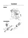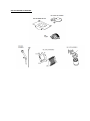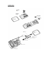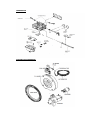
1
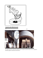
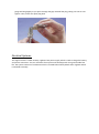
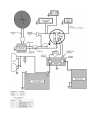
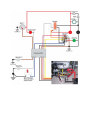
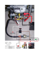
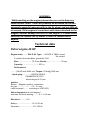
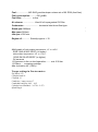
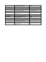
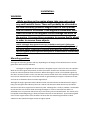
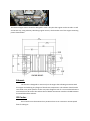
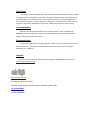
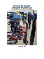
Old Park Lodge,High Road,Earlsheaton,WF12 8BB. TEL: - 01138153880
SOLO 40
Introduction
The Solo engine is a conversion of a commercially available four stroke, 90 degree V twin, OHV
engine. The engine contains a full pressure lubrication system, electronic contactless fixed timings
ignition and a ribbed belt prop reduction drive. This gives a engine with very low maintance
requirements. Providing the engine is maintained as per the procedures laid down in this manual
then the unit should give a long and trouble free life.
All fasteners, nuts, bolts and screws are of a metric size and should be tightened to the correct
torque settings as laid out in this manual.
-----------------------------------------------------------------------------------------------------------------------------------
WARNING.
Although the engine should give a long and trouble free life it should be noted that any engine can
stop suddenly and should not be used in any situation where this would possibly lead to injury.
Although these engines have undergone considerable durability testing they have not been certified
to any standards for use or safety. The engine should there fore be used only in experimental
vehicles where an engine failure will not compromise safety. The user assumes all risks and in there
use acknowledges this warning that the engine can fail at any time with no prior warning.
----------------------------------------------------------------------------------------------------------------------------------
Fuel.
The engine is designed to run on petrol to a minimum specification of 87 octane / 87AKI (91RON) .
NO OIL IS TO BE ADDED TO THE FUEL.
Care must be taken to avoid water contamination of fuel. The usual cause of water contamination is
the source ,it is advisable to always use a water separation filter in your funnel when adding fuel.
Another source is condensation from fuel containers being stored in a partially empty condition. This
can lead to condensation forming on the surfaces above the fuel level which will then be mixed with
the fuel. All containers should always be stored full. However it should be noted that a fuel container
should never be stored in a position where it may be subject to any heat. This can cause expansion
by gassing and could cause some containers to split open due to the increase in pressure. Never use
fuel which has been stored for a long period of time.
OIL.
Use a high quality detergent oil classified for SF, SH, SG ,SF or higher. Do not use any additives.
10W 30. Can be used for temperatures between -18 to 38 C deg. This oil is good for use in varying
temperatures but may increase oil consumption in temperatures above 28 C .The oil level should be
checked more frequently at higher temperatures.
5W 30 SYNTHETIC. This oil is the preferred standard and is highly recommended. Giving protection
from -30 to 40 C deg. This oil gives the best protection at all temperatures with less oil consumption.
The oil also improves starting.
Oil Capacity.
The engine contains 1.6 litres including the filter. The engine is shipped when new containing no oil.
Please fill to the full mark before starting. Do not overfill the engine as this will cause damage.
Filling with oil.
On first use or when performing an oil change remove the oil cap and carefully pour 1 litre of oil into
the engine.
Wait for 30 seconds for oil to settle.
Start the engine for 30 seconds and turn off.
Wait for 30 seconds.
Add oil slowly checking the dipstick level frequently until the oil is at the upper mark on the dip stick.
DO NOT OVERFILL. THIS WILL DAMAGE YOUR ENGINE. IF OVERFILLED REMOVE OIL UNTIL THE
CORRECT LEVEL IS INDICATED. DO NOT START THE ENGINE UNTIL OIL IS AT THE CORRECT LEVEL.
Checking oil level.
With the engine in a level attitude remove the dipstick and wipe with a clean cloth.
Replace the dipstick in to the engine pushing down firmly, then remove and check indicated oil level.
Oil should be at the upper oil mark on the dipstick.
If oil is required then clean around the oil filler cap and remove. Add oil slowly until the oil is at the
correct level as indicated on the dipstick.
Tighten the oil filler cap and ensure the dipstick is replaced before starting the engine.
Start the engine, run until warm. Stop the engine and allow to cool. Check the oil level again.
Oil Pressure.
Oil pressure can be indicated by a light or a gauge. The minimum oil pressure should be 15 psi./1
bar. Max oil temperature should be no more then 117C.
Changing the Oil.
The oil and filter should be renewed initially at 8 hours and then every 50 hours.
Run the engine till warm.
Clean around the oil drain plug, place a container below the plug and remove to allow the oil to
drain.
When the oil has stopped dripping remove the oil filter by unscrewing in a anticlockwise direction.
Clean the area around the oil filter fitting. Wipe a small amount of clean oil around the seal on the
new oil filter and screw on to the engine tightening to hand tight plus quarter of a turn.
Remove the oil cap and carefully pour 1 litre of oil into the engine.
Wait for 30 seconds for oil to settle.
Start the engine for 30 seconds and turn off.
Wait for 30 seconds.
WARNING
DO NOT OVERFILL. THIS WILL DAMAGE YOUR ENGINE. IF OVERFILLED
REMOVE OIL UNTIL THE CORRECT LEVEL IS INDICATED. DO NOT START THE
ENGINE
Add oil slowly checking the dipstick level frequently until the oil is at the upper mark on the dip stick.
Replace the oil fillercap and the dipstick.
Run the engine . Check Oil Level.
DO NOT OVERFILL. THIS WILL DAMAGE YOUR ENGINE. IF OVERFILLED
REMOVE OIL UNTIL THE CORRECT LEVEL IS INDICATED. DO NOT START THE
ENGINE
Propeller and reduction unit.
Fig1.
Fig2.
The engine comes with a belt prop reduction drive. Propeller should be fitted to this in compliance
with the propeller manufacturers instructions.
The prop reduction belt should be visually inspected for damage or wear has part of your pre engine
start checks. Also check that the belt is tightened correctly by measuring the deflection at the
midpoint. This should be between 5 and 10mm. As marked in fig 1.
WARNING.
DO NOT OVER TIGHTEN AS THIS WILL CAUSE DAMAGE TO THE ENGINE AND
BELT AND MAY LEAD TO PREMATURE FAILURE.
If the deflection is incorrect then it can adjusted by turning the adjusting screw using a 6mm Allen
key. As shown in fig2.
STARTING THE ENGINE.
WARNING.
CHECK OIL BEFORE STARTING. NEW ENGINES DELIVERED WITH OUT OIL. THE
ENGINE MUST NOT BE RUN WITH OUT A CORRECTLY FITTED PROPELLER.
The engine comes with a key start electrical system.
On cold engine apply full choke if fitted. Turn the key until the engine rotates on the starter motor.
When engine fires release key. Apply a small amount of throttle until the engine warms. Turn off
choke as soon as engine temperature allows smooth running with out choke. If engine fails to start
immediately turn off the key wait 10 seconds and repeat the above.
On a warm engine the application of the choke may not be needed.
Run in period.
In general, there is no special engine operation procedure required during the break-in period.
Break-in period is accomplished at any speed above idle and may occur faster if the engine is
operated at varying loads and speeds. However, break-in occurs at an acceptable rate if the engine is
operated at slightly less than top no-load speed. Combustion pressures at this speed are sufficiently
high to cause piston rings to conform to the cylinder wall. It is recommended that an engine not be
operated continuously at full load during the initial hours of operation. This can lead to permanent
deformation of the cylinder bore.
Do not allow the cylinder head temperatures to exceed 200C. If the engine is to be run in a static
position it may be necessary to break in the engine over several short periods of time. This is
because the engine is a free air cooled engine and relies on the passage of air over the cylinder
heads from the forward momentum for cooling. It may be necessary to stop the engine and allow it
to cool in order to stay below the 200C cylinder head limits. It is very important to perform the initial
break-in oil change. After the first 5 - 8 hours of operation, the oil should be changed to remove
asperities that have broken from the bearings of the engine components and cylinder wall. Break-in
can be performed using the recommended grades of standard or synthetic oil.
WARNING.
While working on the engine please take care not to drop any small metallic
items. These will probably be attracted to the extremely powerful magnets
with in the fly wheel and are difficult to remove. If the engine is turned over
with items attached to the magnets serious damage can occur to the engine.
It is some times necessary to remove the fly wheel in order to remove these
objects.
Ignition System.
The unit is supplied with a Magnetron Electronic Ignition system on each cylinder. This means
that a complete failure of the engine caused by an ignition fault should be very rare as the system is
independent on each cylinder.
The system is also maintance free with the only requirement being
1.
Checking of the air gap between the magnets on the flywheel and the pickup on the coil
units. In order to do this turn the engine over until the magnets attached to the fly wheel
are aligned with the pick up. Slacken the two posidrive retaining screws. Using a feeler gauge
set the gap to 0.2 to 0.3mm. Tighten the posidrive retaining screws. Turn the Magnets and
align with the second pick up and repeat.
2. Checking and adjusting the spark plug gap. In order to achieve this disconnect the spark plug
lead. Then, clean the area around the spark plug to avoid getting debris in the combustion
chamber when you remove the plug. Remove the spark plug using a spark plug socket. Clean
light deposits from the plug with a wire brush. and spray-on plug cleaner. NOTE: Never clean a
spark plug with a shot blaster or abrasives. Inspect the spark plug for very stubborn deposits, or
for cracked porcelain or electrodes that have been burned away. If any of these conditions
exists, replace the spark plug. Use a spark plug gauge to measure the gap between the two
electrodes (one straight, one curved) at the tip of your spark plug. If necessary, use a spark plug
gauge to adjust the gap by gently bending the curved electrode. When the gap is correct, the
gauge will drag slightly as you pull it through the gap. Reinstall the plug, taking care not to overtighten. Then, attach the spark plug lead.
Electrical Systems.
The engine contains a 192w 16 amp, regulated 12v power supply which is used to charge the battery
and power accessories. This is a maintance free system and should provide a long and trouble free
life. The system consistes of a alternator which is located behind the flywheel and a regulator which
is attached externally.
Checking and adjusting the Valve clearance.
Turn the flywheel to close both valves. Insert a narrow screwdriver into the spark plug hole and
touch the piston. Turn the flywheel clockwise past top dead centre until the piston has moved down
1/4". Use the screwdriver to gauge the piston's range of motion. PLEASE NOTE: This procedure must
be performed for each cylinder. Check the valve clearance by placing a feeler gauge between the
valve head and the rocker arm. Valve clearance specifications for your engine are in the technical
data section. Adjust the clearances as required by turning the rocker screw. Once adjustments are
completed, tighten the rocker nut. Install the valve cover, using new gaskets, as required, and make
sure the cover is secure.
WARNING.
While working on the engine please take care not to drop any
small metallic items. These will probably be attracted to the two
extremely powerful magnets with in the fly wheel and are difficult
to remove. If the engine is turned over with items attached to the
magnets serious damage can occur to the engine. It is some times
necessary to remove the fly wheel in order to remove these
objects.
Maintance schedule.
First 8Hrs.
Change oil.
Check torque of cylinder head bolts.
Before every start.
Check oil.
Check prop reduction belt tension and visual examination.
Every 25hrs.
Remove prop reduction belt and check for wear or damage. Replace as
necessary.
Check the air ducts and cylinder fins for any debris. i.e. leaves etc.
Every 50 hrs.
Change Oil and filter.
Check plugs.
Every 100hrs.
Service air cleaner.
Service oil cooler.
Check valve clearance.
Clean cooling system.
Replace spark plugs.
Replace inline fuel filter.
Replace prop reduction belt.
Every 1000hrs.
Strip and inspect engine crank, bores and internals.
WARNING.
While working on the engine please take care not to drop any
small metallic items. These will probably be attracted to the two
extremely powerful magnets with in the fly wheel and are difficult
to remove. If the engine is turned over with items attached to the
magnets serious damage can occur to the engine. It is some times
necessary to remove the fly wheel in order to remove these
objects.
Technical data
Petrol engine 40 HP
Engine make: ........SOLO 40 Type: ... 90 DEG V TWIN –tuned
.. Air-cooled
2-cylinder-4-stroke-Motor (gasoline) OHV
Bore......................... 75.5 mm Stroke:........................... 70 mm
Capacity: ............................. 627 cc
Performance:
........ (39 HP) with 4300 min-1 Torque: 70 Nm@ 2900 min
-1
Spark plug: ............... BOSCH FR8DC
CHAMPION RC12YC
electrode gap 0.75 mm
Ignition:
Electro. - Magneto ignition, contactless,
Air gap .......................... 0,2 - 0.3 mm
radio-screened ......... according to VDE 0879
Valve clearance (with cold engine)
Inlet and. Exhaust opening ......... 0,1 - 0.15 mm
Electrical: .......... 12V
Battery ........................... 12 V 9-20 ah
Generator ....................... 12 V 192 W
Fuel: ....................MO GAS gasoline/super octane min of 85 RON (lead free)
Fuel consumption: ......... 295 g/kWh
Fuel filter: ................. in-line
Air cleaner: ................... Kand N oil impregnated Oil Filter.
Carburettor: ......................... horizontal twin throat float type
Rated-rpm:3800min
-1
Max-rpm:4350min
-1
idle rpm.:1280 min -1
Engine oil: ............ Quantity approx. 1.5 l
Multi-grade oil with ambient temperature -15° to +45°C:
SOW 10W-40 API SE/SF (or higher)
with ambient temperature -25° to +15°C:
SOW 5W-20 API SE/SF (or higher)
Oil pressure
Oil pressure in the no-load operation: ....... min 0.35 bar
Oil filters .... screwing cartridge
Max Inclination 45° (100%)
Torque settings in Newton metres.
Fly Wheel 175.
Cylinder head 19.
Con Rod 13
Crankcase / sump covers 17
Crankshaft end play .003 – .015
Cylinder bore Standard – 2.9724 – 2.973
Spark Plug 8
Notes for your safety.
-Never operate an engine in an enclosed area.
- Work in a space with ample room for manoeuvring around the engine.
-Do not have an open flame or smoke near flammable liquids.
- Do not refuel an engine while it is operating. Allow the engine to adequately cool before
refuelling.
-Do not operate an engine if gas has spilled. Move the engine away from the spill and avoid
creating any ignition until the gas has evaporated.
-Be familiar with engine shutoff procedures for quick response in an emergency.
-Do not operate an engine with the air cleaner removed.
-Refuel an engine outdoors or in an approved area with proper ventilation and fire safety
equipment.
-Do not operate an engine without a muffler.
-Never leave an operating engine unattended.
-Avoid contact with hot engine parts such as the muffler. cylinder head,. or cooling fins.
-Keep feet, hands, and clothes away from moving engine and equipment components.
Perform service and maintenance procedures with the engine not operating if possible.
Fault Finding.
SYMPTOM
Engine will not start.
POSSIBLE CAUSE
Fuel System.
No Fuel
Old fuel
Fuel tap turned off
Choke( If fitted) in incorrect position.
Clogged fuel filter or fuel line.
Fuel Vent blocked.
Blocked air filter.
Carbarator blocked.
Ignition
Ignition switch in off position.
Wet spark Plug (flooded)
Fouled plug.
Plug cable damaged.
Plug cap damaged.
Ignition coil air gap incorrectly set
Short to earth on ignition or kill switch
if fited.
Defective ignition coil.
Compresion.
Loose spark plug.
Valves out of adjustment.
Worn piston rings
Worn cylinder bore.
Failed head gasket.
Worn valve guides or poor seating of
valve.
Worn camshaft.
Engine fails to idle
correctly.
Stale fuel or incorrect grade fuel
Idle speed incorrect.
Spark plug gap incorrect.
Defective plug.
ACTION.
Fill fuel tank.
Drain and refill tank with new
fuel.
Turn tap on.
Adjust choke to correct
position.
Replace.
Locate Vent hole and clear.
Replace or service( depends on
type)
Service Carb.
Switch on.
Remove plugs and dry.
Replace.
Replace.
Replace.
Set air gap.
Inspect and replace faulty wire.
Replace.
Re tighten.
Adjust.
Replace.
Rebore or replace liners.
replace.
Top end valve service.
replace.
Replace.
Adjust.
Adjust.
Replace.
Ignition coil air gap incorrect.
Defective ignition coil.
Blocked carbarator
Incorrect tappet adjustment
Valve not seating correctly.
Worn cam shaft.
Blocked air filter.
Engine stalls.
Stale fuel or incorrect grade fuel
Idle speed incorrect.
Fouled plug.
Clogged fuel filter or fuel line.
Incorrect tappet adjustment
Blocked carbarator
Blocked air filter.
Adjust.
Relace.
Blocked carbarator
Ajust.
Top end valve service.
Replace.
Replace or service( depends on
type)
Replace.
Adjust.
Replace.
Replace.
Ajust.
Service.
Replace or service( depends on
type)
Parts Diagrams
This parts diagram is not a complete list and is provided only to give an indication of the assembly
sequence of the engine.
ENGINE BLOCK.
PISTON , CAM AND CRANK.
OIL PICK UP AND FILTRATION.
FRONT CASE
INTAKE
CYLINDER HEADS
CARBARATOR
STARTING AND CHARGEING.
Installation.
WARNING.
While working on the engine please take care not to drop
any small metallic items. These will probably be attracted to
the two extremely powerful magnets with in the fly wheel
and are difficult to remove. If the engine is turned over with
items attached to the magnets serious damage can occur to
the engine. It is some times necessary to remove the fly wheel
in order to remove these objects.
NOTE:- Although these general notes are included to assist you in fitting your
engine Solo Flight will take no responsibility for the manufacture, fitting or use of
any engine mount, components or attached items. Where the engine is fitted to an
item not supplied by Solo Flight that manufactures recommendation should always
take precedent.
Mounting position.
Although the mounting position will vary depending on the design of the vehicle there are certain
guide lines which must be followed.
The engine is supplied with ducts which are designed to pass a flow of air over the cylinders.
With out this the engine will overheat and fail. These ducts should never be obstructed and must
receive an uninterrupted air flow at all times. Where the engine is to be in an enclosed engine bay
the ducts must be routed in such a way that they receive the full force of the airflow. The engine bay
must also be ventilated in such a way that the hot air generated by the engine is allowed to escape
and cool air is allowed to flow round the engine block.
Although the engine generates lower vibration levels it should also be considered that the engine
being a V twin generates vibratory forces in a side to side direction rather then the up and down
direction of the inline engines more commonly used . Although this is rarely a problem it is advisable
to take this fact into account while mounting the engine. In order to minimise this effect it is
advisable to use a top mount which uses any of the mount points indicated below. This mount must
be capable of absorbing energy in both the forward and side to side direction. Thus minimising both
stress on the engine mount from the effects of thrust but also minimising the effects of both
vibration at low speed and engine torque at higher speeds.
The bottom engine mount should be designed in such a way that the engine can be carried in a safe
and secure way, using vibratory absorbing engine mounts, which makes use of the engine mounting
points shown below.
Exhaust.
The exhaust is designed to mount only to the engine thus allowing movement with
the engine and reducing any fatigue of the exhaust components. The exhaust should not be
restrained in any other position as this may cause fatigue cracks. If a non standard exhaust is
used which must be mount else where then a flexible connection must be included between
the manifold and the exhaust.
Oil Cooler.
The oil cooler must be mounted in a position where it can receive an uninterrupted
flow of cooling air.
Fuel Pump.
The engine comes equipped with a pressure operated fuel pump. This will be capable
of supplying fuel to the engine in most cases. However using this pump it should be noted
that depending on fuel tank location it may be necessary to use a fuel priming bulb when
first starting the engine in order to prime the carburettor. If the fuel tank is lower then the
engine it is some times desirable to replace the standard pump with an electric pump.
Instrumentation.
Minimum instrumentation fitted for this engine should be , EGT, CHT, RPM, OIL
WARNING. These are required in order to monitor engine limits. Instruments should be
fitted to the manufactures instructions.
Documentation.
It is desirable to maintain an engine log book in order to record hours run and service
items carried out. Any problems should also be noted in this book as this may help in
diagnosing any problems.
Support.
Any technical queries can be directed to Solo Flight on 01138153880, or by email at
[email protected].
www.soloflightltd.com
Solo Flight Ltd, Registered office: -
Old Park Lodge, High Road, Earlsheaton, Dewsbury,WF12 8BB.
Tel:-01138153880
VAT No. 907964096