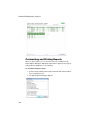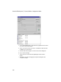
1
Protein Interaction Analysis
ProteOn™ XPR36
Protein Interaction Array System
User Manual
™™
ProteOn XPR36
Protein
Interaction
Array System
Version 3.1 User Manual
BIO-RAD TECHNICAL SUPPORT
Bio-Rad Technical Support in the United States is open Monday-Friday,
5:00 am to 5:00 pm, Pacific Standard Time.
Phone:
800-424-6723 (U.S. and Canada Only)
Fax:
510-741-5802
E-mail:
[email protected] (USA and Canada Only)
Visit us on the Web at discover.bio-rad.com.
For international customers, contact your local Bio-Rad office. Contact
information for the Bio-Rad offices is available on the Web and on the back
cover of this manual.
Worldwide technical support is available on the Web at consult.bio-rad.com.
NOTICES
No part of this publication may be reproduced or transmitted in any form or by
any means, electronic or mechanical, including photocopying, recording, or
any information storage or retrieval system, without permission in writing from
Bio-Rad.
When running ProteOn Manager™ software in regions of the world where
decimals are expressed as commas, an error reading floating point values
might occur. Please use U.S. English numeric and date formats, as set in the
Control Panel, to avoid this problem. ProteOn Manager software has been
certified to run only using U.S. English.
TRADEMARKS
Adobe is a trademark of Adobe Systems Incorporated. Excel, Windows,
Windows Server, and Windows XP are trademarks of Microsoft Corporation.
The MySQL database is licensed from and owned by MySQL AB, a subsidiary
of Sun Microsystems, Inc. The program 7-Zip is used to extract database
files. It is licensed under a GNU LGPL license. You may find the source code
and other information at www.7-zip.org. NeutrAvidin is a trademark of Pierce
Biotechnology, Inc. Contrad is a trademark of Decon Laboratories. Kimwipes
is a trademark of Kimberly-Clark Corporation. Tween is a trademark of ICI
Americas Inc. HASP is a trademark of SafeNET Inc.
iii
ProteOn XPR36 System |
LIMITATIONS OF LIABILITY
Bio-Rad is not responsible for the misinterpretation of results obtained by
following the instructions in this manual. Whenever possible, you should
contact the Technical Support Department at Bio-Rad to discuss your results.
As with all scientific studies, we recommend that you repeat your experiment
at least once before making any significant conclusions for presentation or
publication.
Copyright © 2011 by Bio-Rad Laboratories, Inc. All rights reserved.
REFERENCES
Antibody characterization and development using the ProteOn™ XPR36
protein interaction array system, Bio-Rad Bulletin 5412 (2007)
Bravman T et al. (2006). Exploring 'One-shot' Kinetics™ and small-molecule
analysis using the ProteOn™ XPR36 array biosensor, Analytical Biochemistry,
Vol. 358, Issue 2, pp. 281–288.
Bravman T et al. (2007). Screening, ranking, and epitope mapping of antihuman IL–9 supernatants, Bio-Rad Bulletin 5540.
Bravman T et al. (2008). The ProteOn™ XPR36 array system – high throughput
kinetic binding analysis of biomolecular interactions, Cellular and Molecular
Bioengineering, Vol. 1, pp. 216–228.
Bronner V et al. (2010). Rapid assay development and optimization for small
molecule drug discovery, Bio-Rad Bulletin 5797.
Bronner V et al. (2009). Rapid screening and selection of optimal antibody
capturing agents using the ProteOn™ XPR36 protein interaction array system,
Bio-Rad Bulletin 5820.
Bronner V et al. (2010). Therapeutic antibodies: Discovery and development
using the ProteOn XPR36 biosensor interaction array system, Analytical
Biochemistry, Vol. 406, Issue 2, pp. 147–156.
Bronner V et al. (2006). Rapid and efficient determination of kinetic rate
constants using the ProteOn™ XPR36 protein interaction array system, BioRad Bulletin 3172.
Bronner V et al. (2006). Mechanisms of protein-protein binding: double mutant
cycle analysis using the ProteOn™ XPR36 system, Bio-Rad Bulletin 5358.
Bronner V et al. (2006). Rapid and detailed analysis of multiple antigenantibody pairs using the ProteOn™ XPR36 protein interaction array system,
Bio-Rad Bulletin 5360.
Bronner V et al. (2006). Rapid optimization of immobilization and binding
conditions for kinetic analysis of protein-protein interactions using the
ProteOn™ XPR36 protein interaction array system, Bio-Rad Bulletin 5367.
iv
Bronner V et al. (2006). Analysis of multiple protein-protein interactions using
the ProteOn™ XPR36 protein interaction array system, Bio-Rad Bulletin 5368.
Cohen S et al. (2010). Applications of the ProteOn™ NLC sensor chip:
antibody-antigen, DNA-protein, and protein-protein interactions, Bio-Rad
Bulletin 5449.
Moriarty L. (2010). Guide to ligand immobilization on the ProteOn™ XPR36
system, Bio-Rad Bulletin 5821.
Nahshol O et al. (2008). Parallel kinetic analysis and affinity determination of
hundreds of monoclonal antibodies using the ProteOn™ XPR36, Analytical
Biochemistry, Vol. 383, Issue 2, pp. 52–60.
Stephen A et al. (2009). Determining the binding kinetics of HIV–1
nucleocapsid protein to six densities of oligonucleotide using the ProteOn™
XPR36 protein interaction array system, Bio-Rad Bulletin 5846.
Tabul M et al. (2010). Rapid, high-throughput screening of protein kinase
inhibitors using the ProteOn™ XPR36 protein interaction array system, BioRad Bulletin 5965.
Turner B et al. (2008). Applications of the ProteOn™ GLH sensor chip:
interactions between proteins and small molecules, Bio-Rad Bulletin 5679.
SAFETY
Your safety is important to us. The ProteOn™ XPR36 protein interaction array
system contains components that, if handled improperly, are potentially
harmful. The protection provided by the equipment can be compromised or
the warranty voided if the equipment is used in a manner not specified by
Bio-Rad Laboratories. Bio-Rad recommends that all system users become
familiar with the comprehensive operating procedures and safety information
in this manual. This information alerts you to potential hazards. Please review
all safety information and adhere to standard laboratory safety practices.
WARNING NOTICES USED IN THIS MANUAL
The triangle warning symbol indicates the possibility of personal
injury or damage to the equipment if instructions are not followed.
ELECTRICAL SAFETY
The instrument must be connected only to an approved power
source. Use a grounded socket that meets power requirements. For
more information, refer to Appendix B Specifications and
Requirements on page 209.
Do not attempt to clean the instrument’s electrical components.
v
ProteOn XPR36 System |
In the event of a fluid leak, turn off all power to the system and disconnect all
power cords. Contact Bio-Rad Laboratories for further information.
UNINTERRUPTIBLE POWER SUPPLY
An uninterruptible power supply is recommended to protect the ProteOn
XPR36 from an unstable main power source, harmful spikes, surges or total
blackouts.
This table contains minimum specifications for an uninterruptible power
supply that can be used with the ProteOn instrument.
Specification
120 VAC
230 VAC
Output power capacity
1,500 VA
1,500 VA
Nominal input voltage
120 V
230 V
Minimum 15 min at full load
Minimum 15 min at full load
Backup time
MECHANICAL SAFETY
Use caution when handling the needle tips; they are sharp.
Keep fingers clear of the autosampler during operation.
Shut down the instrument and turn off the power before handling
the autosampler arm, needle holder, or needles.
BIOLOGICAL SAFETY
All human and animal samples may contain hazardous infectious
agents. Follow appropriate biosafety procedures when handling
these products and their containers.
Observe all local, state, and federal biohazard handling
regulations when disposing of biohazardous waste material.
vi
PERSONAL SAFETY
The ProteOn XPR36 instrument weighs 187 lb (85 kg).
Follow all personal safety precautions when moving the
instrument.
If you must lift the instrument, use proper lifting techniques. Have two people
lift the instrument, and use the lifting points indicated below:.
Caution: Bio-Rad strongly recommends that you keep your
boxes for future moving and hire a professional service to safely
move the instrument.
vii
ProteOn XPR36 System |
viii
Contents
Chapter 1. Introduction . . . . . . . . . . . . . . . . . . . . . . . . . . . . . . . . 1
Experiment Workflow . . . . . . . . . . . . . . . . . . . . . . . . . . . . . . . . . . . . . . . . . . . . . 1
ProteOn Manager Software Features . . . . . . . . . . . . . . . . . . . . . . . . . . . . . . . . . 2
Software Overview . . . . . . . . . . . . . . . . . . . . . . . . . . . . . . . . . . . . . . . . . . . . . . . 3
Instrument Log . . . . . . . . . . . . . . . . . . . . . . . . . . . . . . . . . . . . . . 4
Status Bar . . . . . . . . . . . . . . . . . . . . . . . . . . . . . . . . . . . . . . . . . 5
Quick Start Menu . . . . . . . . . . . . . . . . . . . . . . . . . . . . . . . . . . . . 6
Toolbar Icons . . . . . . . . . . . . . . . . . . . . . . . . . . . . . . . . . . . . . . . . . . . . . . 6
ProteOn Manager Software Options . . . . . . . . . . . . . . . . . . . . . . . . . . . 7
Database Browser Views . . . . . . . . . . . . . . . . . . . . . . . . . . . . . . . . . . . . 7
Start Menu Options . . . . . . . . . . . . . . . . . . . . . . . . . . . . . . . . . . . . . . . . . 8
Instrument Shutdown Utility . . . . . . . . . . . . . . . . . . . . . . . . . . . 9
Instrument Log Extraction Utility . . . . . . . . . . . . . . . . . . . . . . . . 9
Backing Up the Database . . . . . . . . . . . . . . . . . . . . . . . . . . . . . . . . . . . 10
Installing ProteOn Manager Software . . . . . . . . . . . . . . . . . . . . . . . . . . . . . . . . 11
Installing ProteOn Manager 3.1 Software . . . . . . . . . . . . . . . . . . . . . . . 11
Upgrading From Earlier Versions (v. 2.1.n, v. 3.0, or v. 3.0.1) to v. 3.1 14
Optimizing the Database . . . . . . . . . . . . . . . . . . . . . . . . . . . . . 14
Reinstalling Version 3.1 . . . . . . . . . . . . . . . . . . . . . . . . . . . . . . . . . . . . . 18
Importing Example Chip Conditioning Protocols . . . . . . . . . . . . . . . . . 19
Importing Files from Another Computer . . . . . . . . . . . . . . . . . . . . . . . . 19
Saving/Exporting Data . . . . . . . . . . . . . . . . . . . . . . . . . . . . . . . . . . . . . . 20
Importing Data from Previous Versions . . . . . . . . . . . . . . . . . . . . . . . . . 20
Starting and Exiting ProteOn Manager Software . . . . . . . . . . . . . . . . . . . . . . . 21
Starting . . . . . . . . . . . . . . . . . . . . . . . . . . . . . . . . . . . . . . . . . . . 21
Exiting . . . . . . . . . . . . . . . . . . . . . . . . . . . . . . . . . . . . . . . . . . . . 21
ProteOn XPR36 Instrument . . . . . . . . . . . . . . . . . . . . . . . . . . . . . . . . . . . . . . . . 22
Starting the Instrument . . . . . . . . . . . . . . . . . . . . . . . . . . . . . . . . . . . . . 22
System Shutdown . . . . . . . . . . . . . . . . . . . . . . . . . . . . . . . . . . . . . . . . . 22
Component Status LEDs . . . . . . . . . . . . . . . . . . . . . . . . . . . . . . . . . . . . 22
Status Bar Instrument State Messages . . . . . . . . . . . . . . . . . . . . . . . . . 23
Inactive State . . . . . . . . . . . . . . . . . . . . . . . . . . . . . . . . . . . . . . 23
Power Up State . . . . . . . . . . . . . . . . . . . . . . . . . . . . . . . . . . . . 24
Initializing State . . . . . . . . . . . . . . . . . . . . . . . . . . . . . . . . . . . . 24
Ready State . . . . . . . . . . . . . . . . . . . . . . . . . . . . . . . . . . . . . . . 24
Running State . . . . . . . . . . . . . . . . . . . . . . . . . . . . . . . . . . . . . . 24
Stop State to Ready State . . . . . . . . . . . . . . . . . . . . . . . . . . . . 25
ix
ProteOn XPR36 System | Contents
Standby State . . . . . . . . . . . . . . . . . . . . . . . . . . . . . . . . . . . . . . 25
Maintenance State . . . . . . . . . . . . . . . . . . . . . . . . . . . . . . . . . . 26
Maintenance Standby State . . . . . . . . . . . . . . . . . . . . . . . . . . . 26
Shutting Down State . . . . . . . . . . . . . . . . . . . . . . . . . . . . . . . . 26
Fault State . . . . . . . . . . . . . . . . . . . . . . . . . . . . . . . . . . . . . . . . 26
Flushing State . . . . . . . . . . . . . . . . . . . . . . . . . . . . . . . . . . . . . 27
Buffer System. . . . . . . . . . . . . . . . . . . . . . . . . . . . . . . . . . . . . . . . . . . . 27
Flushing and Priming the System . . . . . . . . . . . . . . . . . . . . . . . 27
Selecting Buffer Bottles . . . . . . . . . . . . . . . . . . . . . . . . . . . . . . 28
Chapter 2. Protocol Design . . . . . . . . . . . . . . . . . . . . . . . . . . . . 31
Creating and Saving Protocols . . . . . . . . . . . . . . . . . . . . . . . . . . . . . . . . . . . . . 31
Creating a Protocol from Rack/Plate Contents . . . . . . . . . . . . 35
Creating Sample Data From a File . . . . . . . . . . . . . . . . . . . . . . 37
Configuring Protocols . . . . . . . . . . . . . . . . . . . . . . . . . . . . . . . . . . . . . . . . . . . . 38
Editing Protocol Sample Details . . . . . . . . . . . . . . . . . . . . . . . . . . . . . . . . . . . . 41
Importing and Adding Racks/Plates . . . . . . . . . . . . . . . . . . . . . . . . . . . 42
Creating Protocol Steps from Sample Panels . . . . . . . . . . . . . . . . . . . 44
Sample Panel Browser . . . . . . . . . . . . . . . . . . . . . . . . . . . . . . . . . . . . . 45
Changing Sample Positions or Copying Samples . . . . . . . . . . . . . . . . 46
Autosampler Layout . . . . . . . . . . . . . . . . . . . . . . . . . . . . . . . . . . . . . . . 47
Creating and Editing Protocol Steps . . . . . . . . . . . . . . . . . . . . . . . . . . . . . . . . 48
Setting Injection Steps . . . . . . . . . . . . . . . . . . . . . . . . . . . . . . . . . . . . . 49
Protocol Editor. . . . . . . . . . . . . . . . . . . . . . . . . . . . . . . . . . . . . 50
Copying and Pasting Protocol Steps . . . . . . . . . . . . . . . . . . . 51
Editing Injection Step Details. . . . . . . . . . . . . . . . . . . . . . . . . . 52
Setting the Buffer Step . . . . . . . . . . . . . . . . . . . . . . . . . . . . . . . . . . . . . 55
Setting the Temperature Step . . . . . . . . . . . . . . . . . . . . . . . . . . . . . . . 56
Setting the Change Rack Step . . . . . . . . . . . . . . . . . . . . . . . . . . . . . . . 57
Setting a Pause Step . . . . . . . . . . . . . . . . . . . . . . . . . . . . . . . . . . . . . . . 58
Protocol Check . . . . . . . . . . . . . . . . . . . . . . . . . . . . . . . . . . . . . . . . . . . . . . . . . 59
Protocol and Sample Reports . . . . . . . . . . . . . . . . . . . . . . . . . . . . . . . . . . . . . 61
Chapter 3. Experiments . . . . . . . . . . . . . . . . . . . . . . . . . . . . . . . 63
Required Materials . . . . . . . . . . . . . . . . . . . . . . . . . . . . . . . . . . . . . . . . . . . . . . 63
Experiment Preparation. . . . . . . . . . . . . . . . . . . . . . . . . . . . . . . . . . . . . . . . . . . 64
Dissolving and Aliquoting ProteOn EDAC and Sulfo-NHS . . . . . . . . . . 64
Preparing the Buffers . . . . . . . . . . . . . . . . . . . . . . . . . . . . . . . . . . . . . . 65
Loading the Buffer Solution . . . . . . . . . . . . . . . . . . . . . . . . . . . . . . . . . 65
Priming the System . . . . . . . . . . . . . . . . . . . . . . . . . . . . . . . . . . . . . . . 66
x
Flushing the System . . . . . . . . . . . . . . . . . . . . . . . . . . . . . . . . . . . . . . . 67
Preparing the Samples . . . . . . . . . . . . . . . . . . . . . . . . . . . . . . . . . . . . . . . . . . . 68
Setting the Autosampler Temperature . . . . . . . . . . . . . . . . . . . . . . . . . 69
Sensor Chips . . . . . . . . . . . . . . . . . . . . . . . . . . . . . . . . . . . . . . . . . . . . . . . . . . . 70
Sensor Chip Types . . . . . . . . . . . . . . . . . . . . . . . . . . . . . . . . . . . . . . . . 71
Storage and Temperature Equilibration . . . . . . . . . . . . . . . . . . . . . . . . 72
Opening the Sensor Chip . . . . . . . . . . . . . . . . . . . . . . . . . . . . . . . . . . . 72
Conditioning the Sensor Chip . . . . . . . . . . . . . . . . . . . . . . . . . . . . . . . 73
GLC, GLM, and GLH Sensor Chip Conditioning. . . . . . . . . . . 73
NLC Sensor Chip Conditioning . . . . . . . . . . . . . . . . . . . . . . . . 75
HTG Sensor Chip Conditioning . . . . . . . . . . . . . . . . . . . . . . . . 75
Initializing the Chip . . . . . . . . . . . . . . . . . . . . . . . . . . . . . . . . . . . . . . . . 76
Inserting and Ejecting the Sensor Chip . . . . . . . . . . . . . . . . . . . . . . . . 76
Chip Loader LEDs . . . . . . . . . . . . . . . . . . . . . . . . . . . . . . . . . . 77
Setting Sensor Chip Temperature . . . . . . . . . . . . . . . . . . . . . . . . . . . . 78
Reusing Chips . . . . . . . . . . . . . . . . . . . . . . . . . . . . . . . . . . . . . . . . . . . 79
Viewing Chip Information . . . . . . . . . . . . . . . . . . . . . . . . . . . . . . . . . . . 80
Running Experiments . . . . . . . . . . . . . . . . . . . . . . . . . . . . . . . . . . . . . . . . . . . . 81
Nonspecific Binding . . . . . . . . . . . . . . . . . . . . . . . . . . . . . . . . . . . . . . . 83
Experiments with Highly Refractive Cosolvents (DMSO) . . . . . . . . . . . 84
Saving and Exporting Experiment Data . . . . . . . . . . . . . . . . . . . . . . . . 86
Managing Experiments . . . . . . . . . . . . . . . . . . . . . . . . . . . . . . . . . . . . . . . . . . . 87
Chapter 4. Analysis . . . . . . . . . . . . . . . . . . . . . . . . . . . . . . . . . . . 89
Tools for Viewing Data . . . . . . . . . . . . . . . . . . . . . . . . . . . . . . . . . . . . . . . . . . . 89
Sensorgram Data Windows . . . . . . . . . . . . . . . . . . . . . . . . . . . . . . . . . . 90
Changing Sensorgram Appearance . . . . . . . . . . . . . . . . . . . . . . . . . . . 91
Changing Sensorgram Appearance in a Dataset . . . . . . . . . . . 92
Changing Sensorgram Views . . . . . . . . . . . . . . . . . . . . . . . . . . . . . . . . 94
Showing Interspot Data . . . . . . . . . . . . . . . . . . . . . . . . . . . . . . 95
Showing Point Minimized Data . . . . . . . . . . . . . . . . . . . . . . . 95
Showing Kinetic Results . . . . . . . . . . . . . . . . . . . . . . . . . . . . . . 95
Viewing Kinetic Data in an Isoaffinity Graph . . . . . . . . . . . . . . 96
Visually Comparing Tabular Data in Screening Graphs . . . . . 97
Excluding Sensorgrams From Manual Processing . . . . . . . . . 99
Comparing Data in Multiple Sensorgram Data Windows . . . . 100
Undo . . . . . . . . . . . . . . . . . . . . . . . . . . . . . . . . . . . . . . . . . . . 101
Redo . . . . . . . . . . . . . . . . . . . . . . . . . . . . . . . . . . . . . . . . . . . 101
Copying Sensorgram Data Windows . . . . . . . . . . . . . . . . . . . . . . . . . 101
Tabulated Data . . . . . . . . . . . . . . . . . . . . . . . . . . . . . . . . . . . . . . . . . . 101
Data Filters and Display Controls . . . . . . . . . . . . . . . . . . . . . . . . . . . . 103
xi
ProteOn XPR36 System | Contents
Choosing a Panel Type . . . . . . . . . . . . . . . . . . . . . . . . . . . . . 103
Selecting a Protocol Step for Analysis . . . . . . . . . . . . . . . . . . 103
Grouping Data for Analysis . . . . . . . . . . . . . . . . . . . . . . . . . . . 103
Interaction Display Options . . . . . . . . . . . . . . . . . . . . . . . . . . . . . . . . . 107
Display Control Grid . . . . . . . . . . . . . . . . . . . . . . . . . . . . . . . . 107
Processing Data . . . . . . . . . . . . . . . . . . . . . . . . . . . . . . . . . . . . . . . . . . . . . . . 108
Selecting a Range on a Sensorgram . . . . . . . . . . . . . . . . . . . 108
Data Processing Tasks . . . . . . . . . . . . . . . . . . . . . . . . . . . . . . . . . . . . 109
Using the Toolbar . . . . . . . . . . . . . . . . . . . . . . . . . . . . . . . . . . 109
Selecting all Graphs . . . . . . . . . . . . . . . . . . . . . . . . . . . . . . . . 109
Copying Data . . . . . . . . . . . . . . . . . . . . . . . . . . . . . . . . . . . . 109
Processing Multiple Tasks . . . . . . . . . . . . . . . . . . . . . . . . . . . 110
Aligning the Injection . . . . . . . . . . . . . . . . . . . . . . . . . . . . . . . 110
Aligning the Baseline . . . . . . . . . . . . . . . . . . . . . . . . . . . . . . . 110
Removing Artifacts . . . . . . . . . . . . . . . . . . . . . . . . . . . . . . . . 110
Moving a Sensorgram . . . . . . . . . . . . . . . . . . . . . . . . . . . . . . 111
Performing Reference Subtraction . . . . . . . . . . . . . . . . . . . . . 111
Displaying Real-Time Data . . . . . . . . . . . . . . . . . . . . . . . . . . . 113
Deleting Report Point and User-Defined Columns . . . . . . . . . 113
Displaying and Hiding Markers . . . . . . . . . . . . . . . . . . . . . . . . 113
Remove Processing . . . . . . . . . . . . . . . . . . . . . . . . . . . . . . . 114
Switching to Raw Dataset . . . . . . . . . . . . . . . . . . . . . . . . . . 114
Processing EV Correction Data . . . . . . . . . . . . . . . . . . . . . . . . . . . . . 115
Working With EVC Calibration Plots . . . . . . . . . . . . . . . . . . . . 117
Creating a Dataset . . . . . . . . . . . . . . . . . . . . . . . . . . . . . . . . . . . . . . . . 118
Renaming a Dataset . . . . . . . . . . . . . . . . . . . . . . . . . . . . . . . . . . . . . . 118
Deleting a Dataset . . . . . . . . . . . . . . . . . . . . . . . . . . . . . . . . . . . . . . . . 119
Analyzing Data. . . . . . . . . . . . . . . . . . . . . . . . . . . . . . . . . . . . . . . . . . . . . . . . . 120
Analysis Datasets . . . . . . . . . . . . . . . . . . . . . . . . . . . . . . . . . . . . . . . . 120
Parameter Types . . . . . . . . . . . . . . . . . . . . . . . . . . . . . . . . . . 120
Specifying Report Points . . . . . . . . . . . . . . . . . . . . . . . . . . . . 121
Specifying Report Points on Concatenated Data . . . . . . . . . 122
Computing Difference Between Report Points . . . . . . . . . . . 122
Viewing Report Points from a Dataset . . . . . . . . . . . . . . . . . . 123
Importing Report Points from Other Datasets . . . . . . . . . . . . 123
Saving Report Points to an External File . . . . . . . . . . . . . . . . 124
Adding a Report Points Column . . . . . . . . . . . . . . . . . . . . . . . 124
Deleting Report Point Columns . . . . . . . . . . . . . . . . . . . . . . . 124
Filtering and Sorting Analysis Results . . . . . . . . . . . . . . . . . . 124
Adding a User-Defined Column . . . . . . . . . . . . . . . . . . . . . . . 124
Deleting a User-Defined Column . . . . . . . . . . . . . . . . . . . . . . 125
Renaming an Analysis Set . . . . . . . . . . . . . . . . . . . . . . . . . . . 125
xii
Deleting an Analysis Set . . . . . . . . . . . . . . . . . . . . . . . . . . . . . 126
Analysis Wizards . . . . . . . . . . . . . . . . . . . . . . . . . . . . . . . . . . . . . . . . . 126
Kinetic Analysis Wizard . . . . . . . . . . . . . . . . . . . . . . . . . . . . . 127
Equilibrium Analysis Wizard . . . . . . . . . . . . . . . . . . . . . . . . . . 132
Concentration Analysis Wizard . . . . . . . . . . . . . . . . . . . . . . . . 134
Ungrouping Analysis Results . . . . . . . . . . . . . . . . . . . . . . . . . . . . . . . . 138
Filtering Analysis Results . . . . . . . . . . . . . . . . . . . . . . . . . . . . . . . . . . . 138
Sorting Analysis Results . . . . . . . . . . . . . . . . . . . . . . . . . . . . . . . . . . . 140
Saving and Exporting Data . . . . . . . . . . . . . . . . . . . . . . . . . . . . . . . . . . . . . . . 141
Exporting Data to a File . . . . . . . . . . . . . . . . . . . . . . . . . . . . . . . . . . . . 141
Exporting Analysis Data . . . . . . . . . . . . . . . . . . . . . . . . . . . . . . . . . . . 142
Copying and Pasting Data to a File . . . . . . . . . . . . . . . . . . . . . . . . . . . 143
Exporting Experiments to a File . . . . . . . . . . . . . . . . . . . . . . . . . . . . . 144
Reports . . . . . . . . . . . . . . . . . . . . . . . . . . . . . . . . . . . . . . . . . . . . . . . . . . . . . . 145
Customizing and Printing Reports . . . . . . . . . . . . . . . . . . . . . . . . . . . 146
Exporting a Report . . . . . . . . . . . . . . . . . . . . . . . . . . . . . . . . . . . . . . . 147
Chapter 5. Maintenance . . . . . . . . . . . . . . . . . . . . . . . . . . . . . . 149
Maintenance and Cleaning Chips . . . . . . . . . . . . . . . . . . . . . . . . . . . . . . . . . . 149
Maintenance Chips (MNT) . . . . . . . . . . . . . . . . . . . . . . . . . . . . . . . . . . 150
Cleaning Chips (CLN) . . . . . . . . . . . . . . . . . . . . . . . . . . . . . . . . . . . . . 151
Instrument Maintenance . . . . . . . . . . . . . . . . . . . . . . . . . . . . . . . . . . . . . . . . . 151
Safety . . . . . . . . . . . . . . . . . . . . . . . . . . . . . . . . . . . . . . . . . . . . . . . . . 151
Scheduled Maintenance Wizards . . . . . . . . . . . . . . . . . . . . . . . . . . . . 152
Maintenance Protocol Solutions . . . . . . . . . . . . . . . . . . . . . . . . . . . . . 153
Maintenance Wizard Instructions . . . . . . . . . . . . . . . . . . . . . . . . . . . . . . . . . . 154
Prime . . . . . . . . . . . . . . . . . . . . . . . . . . . . . . . . . . . . . . . . . . . . . . . . . 154
Weekly . . . . . . . . . . . . . . . . . . . . . . . . . . . . . . . . . . . . . . . . . . . . . . . . 154
Postexperiment . . . . . . . . . . . . . . . . . . . . . . . . . . . . . . . . . . . . . . . . . 155
Clean MCM . . . . . . . . . . . . . . . . . . . . . . . . . . . . . . . . . . . . . . . . . . . . . 155
Syringe Maintenance . . . . . . . . . . . . . . . . . . . . . . . . . . . . . . . . . . . . . . 156
Starting the Syringe Wizard . . . . . . . . . . . . . . . . . . . . . . . . . . 157
Cleaning Syringes . . . . . . . . . . . . . . . . . . . . . . . . . . . . . . . . . . 161
Replacing the Syringes . . . . . . . . . . . . . . . . . . . . . . . . . . . . . . 161
Resuming the Wizard . . . . . . . . . . . . . . . . . . . . . . . . . . . . . . . 162
OQ Protocol . . . . . . . . . . . . . . . . . . . . . . . . . . . . . . . . . . . . . . . . . . . . 165
Shutdown Procedures. . . . . . . . . . . . . . . . . . . . . . . . . . . . . . . . . . . . . . . . . . . 166
Immediate Shutdown . . . . . . . . . . . . . . . . . . . . . . . . . . . . . . . . . . . . . 166
Long-Term Shutdown . . . . . . . . . . . . . . . . . . . . . . . . . . . . . . . . . . . . . 167
Software-Only Shutdown . . . . . . . . . . . . . . . . . . . . . . . . . . . . . . . . . . 168
Exiting ProteOn Manager Software and the Instrument . . . . . . . . . . . 168
xiii
ProteOn XPR36 System | Contents
Emptying the Collection Tank . . . . . . . . . . . . . . . . . . . . . . . . . . . . . . . 169
Chapter 6. ProteOn System Troubleshooting . . . . . . . . . . . . 171
Common Concerns . . . . . . . . . . . . . . . . . . . . . . . . . . . . . . . . . . . . . . . . . . . . . 171
Nonspecific Binding . . . . . . . . . . . . . . . . . . . . . . . . . . . . . . . . . . . . . . . . . . . . 172
Background . . . . . . . . . . . . . . . . . . . . . . . . . . . . . . . . . . . . . . 172
Addressing the Causes of NSB . . . . . . . . . . . . . . . . . . . . . . . 173
Firewall Settings . . . . . . . . . . . . . . . . . . . . . . . . . . . . . . . . . . . . . . . . . . . . . . . 174
High Throughput Screening Analyses . . . . . . . . . . . . . . . . . . . . . . . . . . . . . . . 175
Chapter 7. Security Edition . . . . . . . . . . . . . . . . . . . . . . . . . . . 177
Background on U.S. FDA Part 11 Regulations (21 CFR Part 11) . . . . 177
Standard Mode vs. Secure Mode . . . . . . . . . . . . . . . . . . . . . . . . . . . . 178
System Requirements . . . . . . . . . . . . . . . . . . . . . . . . . . . . . . . . . . . . . 178
Installing and Starting ProteOn Manager Software, Security Edition. 178
Enabling and Disabling Secure Mode . . . . . . . . . . . . . . . . . . . . . . . . 179
Users, Passwords, and User Levels . . . . . . . . . . . . . . . . . . . . . . . . . . 180
User Level Restrictions . . . . . . . . . . . . . . . . . . . . . . . . . . . . . . 180
User Access by Function. . . . . . . . . . . . . . . . . . . . . . . . . . . . 180
User Authentication . . . . . . . . . . . . . . . . . . . . . . . . . . . . . . . . 181
File Security and Validation . . . . . . . . . . . . . . . . . . . . . . . . . . . . . . . . . 182
Importing/Exporting Secure Files . . . . . . . . . . . . . . . . . . . . . . 182
ProteOn Manager Software Logs. . . . . . . . . . . . . . . . . . . . . . . . . . . . 182
Secure Documents . . . . . . . . . . . . . . . . . . . . . . . . . . . . . . . . . . . . . . . 182
Signed Files . . . . . . . . . . . . . . . . . . . . . . . . . . . . . . . . . . . . . . . . . . . . 183
Signed Datasets and Analysis Sets . . . . . . . . . . . . . . . . . . . . . . . . . . . 184
Audit Trail . . . . . . . . . . . . . . . . . . . . . . . . . . . . . . . . . . . . . . . . . . . . . . 184
Viewing the Audit Trail . . . . . . . . . . . . . . . . . . . . . . . . . . . . . . 186
Protected Directories . . . . . . . . . . . . . . . . . . . . . . . . . . . . . . . . . . . . . . 187
Logging Off. . . . . . . . . . . . . . . . . . . . . . . . . . . . . . . . . . . . . . . . . . . . . 187
Changing Data Ownership . . . . . . . . . . . . . . . . . . . . . . . . . . . . . . . . . 188
A. ProteOn XPR36 Instrument and Peripherals . . . . . . . . . . 189
Instrument Front View . . . . . . . . . . . . . . . . . . . . . . . . . . . . . . . . . . . . . . . . . . . 190
Instrument Side View. . . . . . . . . . . . . . . . . . . . . . . . . . . . . . . . . . . . . . . . . . . . 191
Instrument LEDs . . . . . . . . . . . . . . . . . . . . . . . . . . . . . . . . . . . . . . . . . 192
Chip Loader and Chip Eject Button . . . . . . . . . . . . . . . . . . . . . . . . . . 193
Buffer Control Buttons . . . . . . . . . . . . . . . . . . . . . . . . . . . . . . . . . . . . 193
Serial Numbers . . . . . . . . . . . . . . . . . . . . . . . . . . . . . . . . . . . . . . . . . . 194
Cables and Power Switch . . . . . . . . . . . . . . . . . . . . . . . . . . . . . . . . . . 195
xiv
Ventilation . . . . . . . . . . . . . . . . . . . . . . . . . . . . . . . . . . . . . . . . . . . . . . 195
Inside the Instrument. . . . . . . . . . . . . . . . . . . . . . . . . . . . . . . . . . . . . . . . . . . . 197
Buffer System. . . . . . . . . . . . . . . . . . . . . . . . . . . . . . . . . . . . . . . . . . . 197
Microfluidics System Components . . . . . . . . . . . . . . . . . . . . . . . . . . . 198
Autosampler . . . . . . . . . . . . . . . . . . . . . . . . . . . . . . . . . . . . . . . . . . . . 199
Thermal Platform . . . . . . . . . . . . . . . . . . . . . . . . . . . . . . . . . . . . . . . . . 199
Needle Holder with Sampling Needles . . . . . . . . . . . . . . . . . . . . . . . . 200
Changing the Needle Holder and Needles . . . . . . . . . . . . . . . . . . . . . 200
Wash Station . . . . . . . . . . . . . . . . . . . . . . . . . . . . . . . . . . . . . . . . . . . 202
Sample Holders . . . . . . . . . . . . . . . . . . . . . . . . . . . . . . . . . . . . . . . . . . 203
Sample Holder Sensors . . . . . . . . . . . . . . . . . . . . . . . . . . . . . 204
Syringe Pumps . . . . . . . . . . . . . . . . . . . . . . . . . . . . . . . . . . . . . . . . . . 204
Multichannel Module . . . . . . . . . . . . . . . . . . . . . . . . . . . . . . . 205
Optical Detection System . . . . . . . . . . . . . . . . . . . . . . . . . . . . . . . . . . 205
Reservoir, Overflow Sensor, and Drain Pump . . . . . . . . . . . . . . . . . . . 206
Computer and Display. . . . . . . . . . . . . . . . . . . . . . . . . . . . . . . . . . . . . . . . . . . 206
HASP Keys . . . . . . . . . . . . . . . . . . . . . . . . . . . . . . . . . . . . . . . . . . . . . 207
B. Specifications and Requirements . . . . . . . . . . . . . . . . . . . 209
System Specifications . . . . . . . . . . . . . . . . . . . . . . . . . . . . . . . . . . . . . . . . . . . 209
Detection System . . . . . . . . . . . . . . . . . . . . . . . . . . . . . . . . . . . . . . . . 209
Detection Limits . . . . . . . . . . . . . . . . . . . . . . . . . . . . . . . . . . . . . . . . . . 209
Working Ranges (Typical Values) . . . . . . . . . . . . . . . . . . . . . . . . . . . . 210
Fluidics . . . . . . . . . . . . . . . . . . . . . . . . . . . . . . . . . . . . . . . . . . . . . . . . 210
Physical . . . . . . . . . . . . . . . . . . . . . . . . . . . . . . . . . . . . . . . . . . . . . . . 210
Installation Requirements . . . . . . . . . . . . . . . . . . . . . . . . . . . . . . . . . . . . . . . . 211
Electrical Requirements . . . . . . . . . . . . . . . . . . . . . . . . . . . . . . . . . . . 211
Bench Requirements . . . . . . . . . . . . . . . . . . . . . . . . . . . . . . . . . . . . . 211
Recommendations . . . . . . . . . . . . . . . . . . . . . . . . . . . . . . . . . . . . . . . 211
Environmental Requirements . . . . . . . . . . . . . . . . . . . . . . . . . . . . . . . 212
Chemical Compatibility . . . . . . . . . . . . . . . . . . . . . . . . . . . . . . . . . . . 212
C. Surface Plasmon Resonance. . . . . . . . . . . . . . . . . . . . . . . 213
Biomolecular Applications. . . . . . . . . . . . . . . . . . . . . . . . . . . . . . . . . . . . . . . . 213
Interaction Analysis . . . . . . . . . . . . . . . . . . . . . . . . . . . . . . . . . . . . . . . . . . . . . 214
Ligand Immobilization Steps . . . . . . . . . . . . . . . . . . . . . . . . . . . . . . . . 214
Analyte Interaction Steps . . . . . . . . . . . . . . . . . . . . . . . . . . . . . . . . . . 214
Ligand Immobilization Process . . . . . . . . . . . . . . . . . . . . . . . . . . . . . . . . . . . . 215
Immobilization Chemistries . . . . . . . . . . . . . . . . . . . . . . . . . . . . . . . . . 215
Direct, Covalent Coupling . . . . . . . . . . . . . . . . . . . . . . . . . . 215
xv
ProteOn XPR36 System | Contents
Noncovalent Coupling . . . . . . . . . . . . . . . . . . . . . . . . . . . . . . 215
Activation Step (Amine Coupling). . . . . . . . . . . . . . . . . . . . . . . . . . . . 216
Immobilization Step . . . . . . . . . . . . . . . . . . . . . . . . . . . . . . . . . . . . . . 216
Determining the Optimum pH for Immobilization . . . . . . . . . . . . . . . . . . . . . . 219
Deactivation and Stabilization Steps . . . . . . . . . . . . . . . . . . . . . . . . . 220
Determining the Extent of Ligand Immobilization . . . . . . . . . . . . . . . 221
Analyte Interaction Process. . . . . . . . . . . . . . . . . . . . . . . . . . . . . . . . . . . . . . . 222
Analyte Step . . . . . . . . . . . . . . . . . . . . . . . . . . . . . . . . . . . . . . . . . . . . 222
Regeneration Step . . . . . . . . . . . . . . . . . . . . . . . . . . . . . . . . . . . . . . . 224
D. Protocol Development Kits . . . . . . . . . . . . . . . . . . . . . . . . 225
One-shot Kinetics™ (OSK)™ Kit . . . . . . . . . . . . . . . . . . . . . . . . . . . . . . . . . . . 225
Multiple Protein Interaction Kit . . . . . . . . . . . . . . . . . . . . . . . . . . . . . . . . . . . . 225
Protein–Small Molecule Kit . . . . . . . . . . . . . . . . . . . . . . . . . . . . . . . . . . . . . . . 226
E. Ordering Information. . . . . . . . . . . . . . . . . . . . . . . . . . . . . . 227
How to Order. . . . . . . . . . . . . . . . . . . . . . . . . . . . . . . . . . . . . . . . . . . . . . . . . . 227
Payment . . . . . . . . . . . . . . . . . . . . . . . . . . . . . . . . . . . . . . . . . . . . . . . 227
Phone-in Hours . . . . . . . . . . . . . . . . . . . . . . . . . . . . . . . . . . . . . . . . . . 227
Information Needed . . . . . . . . . . . . . . . . . . . . . . . . . . . . . . . . . . . . . . . 227
Materials and Supplies . . . . . . . . . . . . . . . . . . . . . . . . . . . . . . . . . . . . 228
F. Security Edition Configuration Guide . . . . . . . . . . . . . . . . 233
Standard Mode vs. Secure Mode . . . . . . . . . . . . . . . . . . . . . . . . . . . . . . . . . . 233
Security Edition Hardware Protection Key (HASP Key) . . . . . . . . . . . 233
ProteOn Manager Software Users and Groups . . . . . . . . . . . . . . . . . . . . . . . 234
ProteOn Manager Software User Groups . . . . . . . . . . . . . . . . . . . . . . 234
Configuring Users and Groups on the Local Computer . . . . . . . . . . . . . . . . . 235
Configuring Users and Groups on a Network Domain . . . . . . . . . . . . . . . . . . 239
Windows Server . . . . . . . . . . . . . . . . . . . . . . . . . . . . . . . . . . . . . . . . . 239
Password Security . . . . . . . . . . . . . . . . . . . . . . . . . . . . . . . . . . . . . . . . . . . . . 242
Password Policy Setting Examples . . . . . . . . . . . . . . . . . . . . . . . . . . 243
Account Lockout Policy Setting Examples . . . . . . . . . . . . . . . . . . . . 243
Auditing Windows Event Logs . . . . . . . . . . . . . . . . . . . . . . . . . . . . . . . . . . . . 244
Miscellaneous Security Measures. . . . . . . . . . . . . . . . . . . . . . . . . . . . . . . . . . 245
Glossary . . . . . . . . . . . . . . . . . . . . . . . . . . . . . . . . . . . . . . . . . . 247
Index . . . . . . . . . . . . . . . . . . . . . . . . . . . . . . . . . . . . . . . . . . . . . 259
xvi
ProteOn XPR36 System
1
Introduction
The ProteOn™ XPR36 protein interaction array system consists of the
ProteOn™ XPR36 instrument, the controller (the computer attached to the
instrument), a HASP key, and ProteOn Manager™ software. This manual
describes how to use the ProteOn XPR36 protein interaction array instrument
with ProteOn Manager software.
This chapter describes the experiment workflow and provides an overview of
ProteOn Manager software. It describes the software layout and tools and
how to upgrade the software and start the ProteOn system. Chapter 7
explains how to use the optional ProteOn Manager software, Security Edition.
This chapter also has instructions for controlling the instrument and explains
the LED indicators, various instrument states, and the buffer control system.
Experiment Workflow
ProteOn Manager software controls the operation, data collection, data
analysis, and maintenance of the ProteOn XPR36 instrument. The software
license permits its installation and use on both the controller and on a
separate PC for offline protocol creation and data analysis.
Tabs in the software navigation panel guide you through the experiment
workflow.
Steps
Navigator Tab
Navigator Tab Functions
1 Configure the
instrument
Instrument
Set up the instrument, initialize a sensor chip, set the
autosampler temperature, choose buffers, view the
instrument log, and perform routine maintenance
2 Design or edit a Protocol
protocol
Create and edit protocols; define samples, protocol
steps, and sample layout for a protocol; and print the
protocol and sample layouts
3 Run and view an Run
experiment
Run an experiment and view the status of an
experiment in progress
4 Data processing Data
Displays only when an experiment is open; organize
data for processing and analysis and create and view
datasets
1
ProteOn XPR36 | Introduction
Steps
Navigator Tab
Navigator Tab Functions
5 Analyze the
datasets
Analysis
Datasets
Displays only when an experiment is open; analyze
selected processed datasets and view existing analysis
data
ProteOn Manager Software Features
Software feature descriptions and manual pages where they are discussed.
Quick Start Menu
Rapid navigation to commonly performed tasks
page 6
Instrument Control
Log continuously records instrument and application events
Maintenance wizards and protocols
MCM (multichannel module) maintenance procedure wizard
page 4
page 152
page 155
Protocol Design
Predesigned, application-based protocol templates assist with experiment design
Guided stepwise protocol setup
page 32
page 44
Protocol Sample Editor
Easy sample entry and viewing; import
Assign samples to racks or microplates
Sample layout screen displays rack/microplate position and required volume for each sample
Sample layout report can be printed and used as a guide to fill racks or microplates
page 42
page 44
page 61
page 61
Protocol Step Editor
Drag-and-drop protocol step editor for easy protocol creation
Drag and drop commonly used step groups for organization and rapid protocol creation
Graphical interaction layout to guide experiment setup
page 50
page 51
page 52
Data Controls
Data viewing, organization, and processing controls
Sample panel chooser filters datasets by type of sample: activator, ligand, deactivator,
regenerator, analyte, blank, and excluded volume (EV) correction calibration standard
Protocol step chooser selects protocol steps from which data are viewed
Data grouping chooser organizes data into groups for display, processing, and analysis
Interaction display chooser to select, view, and hide interaction data (sensorgrams) and their
sample information
2
page 89
page 45
page 48
page 103
page 107
Software Overview
Database
Database browser allows easy access and reuse of templates, protocols, or experiments
page 32
Analysis Datasets
Kinetic, equilibrium, and concentration data analysis wizards
Report point creation to allow response unit (RU) comparisons
Isoaffinity graphs allow the visualization of kinetics
Screening graphs compare values from Data tab or Analysis tab tables
page 126
page 121
page 96
page 98
Security Edition
Optional Security Edition aids compliance with U.S. FDA 21 CFR Part 11 regulations
page 177
Software Overview
ProteOn Manager software opens to the Instrument Control screen, with the
Quick Start menu open:
Title bar
Menu bar
Toolbar
Navigation
panel
Content area
Status bar
Each screen displays the following items:
• Title bar – displays the application name or name of the selected
protocol or experiment. It also contains buttons to minimize/restore
the window and to exit the program
3
ProteOn XPR36 | Introduction
•
•
•
•
•
Menu bar – consists of the File, Edit, View, Process, Analysis,
Tools, and Help menus, and Security menu (if you have the Security
Edition, see Security Edition on page 177)
Toolbar – includes icons from all screens, but icons are enabled
only when their functions are available
Content area – the right side of the screen displays the
functionality and interaction data associated with the tab chosen in
the navigation panel
Status bar – current instrument information displayed at the
bottom of the screen, described on page 5
Navigation panel – includes tabs to choose among application
functions, which follow the experiment workflow shown on page 1
INSTRUMENT LOG
ProteOn Manager software logs instrument and application events
continuously.
To open the Instrument Log screen:
•
Click Log in the navigation panel
The instrument log displays the following columns of data:
• Date — lists the date and time of logged events (HH/MM/SS
format)
• Event — displays the event type (startup, acquisition, alert, etc.)
• Description — displays a description of the event
• Instrument ID — displays the ID for the instrument being used
• User ID — displays user name for the currently logged on user
(Security Edition only)
• Chip ID — displays ID of inserted chip
• Experiment —displays name of experiment currently running or
being modified
• Access Level — (Security Edition only) displays currently logged
on user access level
• Reason — (Security Edition only) displays the user-given reason
for a change
You can sort the instrument log table by Date, Event, Description, Instrument
ID, User ID, Chip ID, or Experiments, in ascending or descending order.
The log can also be viewed using several filters. For more information, see
Database Browser Views on page 7.
4
Software Overview
To view specified time periods in the log:
1. Select the From Date in the Filter by Date box and enter the time. The
defaults are the date and time when the current ProteOn Manager
session began.
2. Select the To Date in the Filter by Date box and enter the time. The
defaults are the current date and time.
3. To display log events connected with a particular experiment, click the
checkbox, and click Select to choose an experiment from the Database
Browser.
4. Click Apply to display the information.
5. To restore the default date and time settings, click Reset.
STATUS BAR
The status bar appears at the bottom of the Instrument Control screen and
displays the following information.
•
•
•
•
•
•
Instrument State —displays the current instrument state; see
Status Bar Instrument State Messages on page 23 for more
information
Communication Status —green square indicates communication
with the instrument. Red square indicates no communication with
the instrument
Chip — indicates the type of chip in the instrument. See Sensor
Chips on page 70 for more information
Chip Temperature — displays the chip temperature
Sample Temperature — displays the sample temperature
Orientation —displays the current multichannel module (MCM)
state, vertical or horizontal
5
ProteOn XPR36 | Introduction
QUICK START MENU
To display the Quick Start menu, select View Quick Start on the View menu.
Use the Quick Start floating menu to create new protocols, open existing
protocols, and analyze data.
•
•
•
•
New — opens the database browser to create a protocol,
experiment, or template
Open — opens the database browser to select an existing
protocol, experiment, or template
Continue Experiment — opens the Run screen so you can choose
an experiment
Analyze Data — opens the Select Experiment dialog box
To close the Quick Start menu:
•
Click Close on the title bar
To keep the Quick Start menu from opening when you restart the
software:
•
Clear the Show at Startup checkbox
Toolbar Icons
Individual icons are enabled for functions that are available on a screen.
Hovering over an icon displays its function.
6
Software Overview
ProteOn Manager Software Options
In the Options dialog box you can set instrument and software parameters
that improve your workflow.
You can specify the temperature of the sensor chip and autosampler and set
the following defaults:
• Instrument ID
• Sensor Chip Temperature
• Autosampler Temperature
• Default Buffer Valve Position and Buffer Names
To set ProteOn Manager software options:
1. On the Tools menu, select Options. The Options dialog box appears.
2. Edit the settings.
3. Click OK.
Database Browser Views
To access the database browser:
•
Click New in the File menu or in the Quick Start menu. The
database browser appears.
7
ProteOn XPR36 | Introduction
You can change the way the database browser presents information by rightclicking the heading of any column. The right-click menu displays the
following options.
•
•
•
•
•
•
•
Sort Ascending and Sort Descending — Information can be
sorted alphabetically, except the date column, which is sorted by
date and time value
Clear Sorting — returns the display to its default setting
Remove This Column — removes the selected column
Column Chooser — displays a list of columns that can be added
to your database. Drag the new column to the required position.
Columns can also be removed from your database browser by
dragging them out of the browser and into the Customization
screen. The Column Chooser retains the column head and all the
data in the column when you drag a column into it
Best Fit — makes visible the contents of a column
Best Fit (all columns) — attempts to make all columns display
optimally in the available width
Filter Editor — You can filter your results to view only some
information. Display filter choices by clicking the filter icon on the
righthand side of each column. If you choose Custom on the filter
icon menu, you can use the Custom Auto Filter screen to specify
more complex filters. You can specify even more complex filters on
the Filter Builder screen, available by choosing Filter Editor
The same view choices are available in the Instrument Log and Audit Trail
screens.
Start Menu Options
Several utilities are available through the Windows Start menu. Choose Start >
All Programs > ProteOn > and the utility you want to use.
8
Software Overview
INSTRUMENT SHUTDOWN UTILITY
You can shut down the instrument while ProteOn Manager software continues
to run.
To shut down the instrument while ProteOn Manager software continues
to run:
•
Navigate to the Start > All Programs > ProteOn menu and choose
Instrument Shutdown Utility
A message displays the instrument’s progress as it shuts down.
INSTRUMENT LOG EXTRACTION UTILITY
Use this utility to capture a log file to send to Bio-Rad Technical Support for
use in troubleshooting instrument problems. This utility captures a log file
containing all instrument actions since the previous capture. The file name
includes the instrument name, serial number, date, and 24 hr time notations.
Saving all .zip log files to a folder captures a complete history of all instrument
actions.
9
ProteOn XPR36 | Introduction
Backing Up the Database
It is a best practice to back up the database frequently and keep the backup
copies in a safe place. A USB or network hard drive is a good backup
solution. Keep in mind that it can take 10–40 min to back up a large database.
Typically, the database is located at d:\ProteOnManagerDatabase. This
directory structure may also be located in another hard disk location of your
choice.
To back up the database:
1. Exit ProteOn Manager software.
2. Copy the ProteOnManagerDatabase folder to a backup location large
enough to store it.
To restore the database:
1. Exit ProteOn Manager software.
2. Rename the current version of the ProteOnManagerDatabase folder
with a suffix; otherwise this folder will be overwritten when you restore
an earlier version.
3. Copy the earlier version of the ProteOnManagerDatabase folder to your
database location, typically drive D.
10
Installing ProteOn Manager Software
Installing ProteOn Manager Software
You must be a Windows administrator to install or remove ProteOn Manager
software.
The computer attached to the instrument and any stand-alone PC each
require a hardware protection (HASP) key plugged into a USB port for
ProteOn Manager software to analyze an experiment with more than 20 steps.
If you have purchased the optional Security Edition of ProteOn Manager
software, you will also receive an additional Security Edition HASP key, which
enables the Security Edition features. For details, see HASP Keys on
page 207.
Installing ProteOn Manager 3.1 Software
See the Release Notes for ProteOn Manager 3.1 Software for detailed
instructions on installing this version of the software.
To install ProteOn Manager software, version 3.1:
1. Insert the ProteOn Manager software 3.1 CD-ROM into a CD drive.
2. Double-click the file CDBrowserStart.exe. The Proteon Manager
software splash screen appears.
3. Select Install ProteOn Manager in the upper right corner of the screen.
The ProteOn Manager software Installation wizard appears.
11
ProteOn XPR36 | Introduction
4. Click Next. The License Agreement screen appears.
5. Read the License Agreement, then click the button to accept it, and
then click Next. The next screen shows default destination folders for
the program files and the database. The drive with the largest available
space is selected for the database. The database is individual to each
computer and is used by one user at a time.
12
Installing ProteOn Manager Software
6. (Optional) To change the selected directory, click Change and select a
new destination. If you select the D drive, the database is installed in
the root directory.
Note: The database can become as large as 40–50 GB. Choose
a location that has 100 GB free.
7. After choosing a destination, click Next to continue.
8. Click Install on the next screen to begin installation. The wizard installs
files and configures the database.
13
ProteOn XPR36 | Introduction
9. Click Finish when the installation ends.
10. Click the ProteOn Manager icon on the desktop to start the software.
ProteOn Manager software opens and displays the main screen.
Upgrading From Earlier Versions (v. 2.1.n,
v. 3.0, or v. 3.0.1) to v. 3.1
While upgrading ProteOn Manager software, the installation wizard backs up
and updates the database.
There is no need to uninstall an older version of ProteOn Manager software
before installing the 3.1 version. The older version will be uninstalled for you
during the installation process. The data from earlier versions will be copied
directly into ProteOn Manager 3.1 without needing to be imported. Your
previous data are saved.
The existing database directory from the earlier version is chosen by default.
OPTIMIZING THE DATABASE
It is strongly recommended that you use an optimized database. Optimized
databases perform faster and improve the performance of the application.
When you update your system from ProteOn Manager v. 2.1.n, you can
improve the performance of the database by running the ProteOn Database
Optimizer at the end of the installation process.
14
Installing ProteOn Manager Software
If you upgrade from ProteOn Manager v. 3.0 or from v.3.0.1 and you have
previously run the optimizer, your database is already optimized and there is
no need to run the optimizer again during upgrade to ProteOn Manager v. 3.1.
The optimizer reconfigures the database to improve data access time and
allow the data to run to the full storage capacity of the hard disk.
Optimizing a large database can take a considerable amount of time. The
optimizer displays a time estimate and prompts you to choose whether or not
to run it. The optimizer can be run at any time, and it will optimize the
database only once. However, the optimizer cannot run when ProteOn
Manager or any other ProteOn utilities that affect the database are running.
To run the Database Optimizer after the installation process, select it on the
Start menu under ProteOn Manager software.
To upgrade ProteOn Manager Version 2.1.n, v. 3.0, or v. 3.0.1 to ProteOn
Manager Version 3.1:
Note: The Windows 7 operating system might display requests
for permission to perform some activities during the installation
process. You must approve these requests to complete
installation.
Note: If your database is already optimized, installation requires a
free space of at least the size of the database. If your database is
not yet optimized, getting the new application installed along with
optimizing the database requires a free space of at least double
the size of the database.
1. Insert the ProteOn Manager software 3.1 CD-ROM into a CD drive.
2. If the CD does not AutoStart and displays the following screen, doubleclick the file CDBrowserStart.exe. The Proteon Manager software
splash screen appears.
15
ProteOn XPR36 | Introduction
3. Select Install ProteOn Manager in the upper right corner of the screen.
The ProteOn Manager Software Installation wizard appears.
4. Click Next. The License Agreement screen appears.
5. Read the License Agreement, click the button to accept it, and then
click Next. The next screen shows default destination folders for the
program files and the database.
16
Installing ProteOn Manager Software
6. After choosing a destination, click Next to continue. When upgrading to
ProteOn Manager 3.1, the location of the database is predefined by the
location that was used by earlier ProteOn Manager versions.
7. Click Install on the next screen to begin installation. The wizard installs
files and configures the database.
8. Click Finish when the installation ends. The ProteOn Database
Optimizer dialog box appears.
9. If you optimized your database earlier, the database is already
optimized. Close the ProteOn Database Optimizer dialog box and skip
steps 10–12.
10. (Optional) Click Estimate to find out how long it will take to optimize the
database.
11. Click Run to optimize the database.
12. When the optimizer finishes running, it is possible to run a Verify
process, which checks the optimized content of the database. At the
end of the optimization process close the dialog box.
13. Click the ProteOn Manager software icon on the desktop to start the
software. ProteOn Manager software opens and displays the main
screen.
17
ProteOn XPR36 | Introduction
Reinstalling Version 3.1
In the event that ProteOn Manager software v. 3.1 has been uninstalled and its
data remain unchanged, you can reinstall v. 3.1 and continue to use the
database that is already on disk.
To reinstall v. 3.1 and use the same database:
1. Insert the version 3.1 CD-ROM into a CD drive.
2. Double-click the file CDBrowserStart.exe. The Proteon Manager
software splash screen appears.
3. Select Install ProteOn Manager in the upper right corner of the screen.
The ProteOn Manager Installation wizard appears.
4. Click Next. The License Agreement screen appears.
18
Installing ProteOn Manager Software
5. Read the License Agreement, click the button to accept it, and then
click Next. The next screen shows the current destination folders for the
program files and the database.
6. After choosing a destination, click Next to continue.
7. Click Install at the next screen to begin installation. The wizard installs
files and configures the database.
8. Click Finish when the installation ends.
Importing Example Chip Conditioning
Protocols
Once you have installed ProteOn Manager software, you can import example
chip conditioning protocols. These protocols are located on the disk drive
where you installed ProteOn Manager, at Bio-Rad > ProteOn Manager > Chip
Conditioning and Example Protocols.
Importing Files from Another Computer
Experiments and protocols can be transferred from the instrument controller
to a stand-alone computer or drive for convenience and backup.
To import files from another computer:
1. Choose File > Import > Import Experiment/protocol transfer file.
19
ProteOn XPR36 | Introduction
2. In the Browse dialog box select the experiment. The Convert dialog box
appears.
3. Click Import.
Saving/Exporting Data
ProteOn Manager software automatically saves your data to a database. The
data can be exported into a variety of file formats. See Saving and Exporting
Data on page 141 for details.
Importing Data from Previous Versions
Data from previous versions (2.1, 3.0, 3.0.1) can be imported into the new
version.
ProteOn Manager software versions before 2.1 saved experiments and
analysis data to folders instead of to a database. No user name was
associated with experiments in previous versions. If you are using the
Standard Edition of ProteOn Manager software, imported experiments display
the user’s Windows user name. If you are using the Security Edition, the
ProteOn system user name is used.
Experiments, protocols, and templates can be imported into version 2.1.1
from versions previous to 2.1.
20
Starting and Exiting ProteOn Manager Software
Starting and Exiting ProteOn Manager
Software
STARTING
Note: You must first start the instrument and then wait 2 min
before starting ProteOn Manager software.
To start ProteOn Manager software:
•
Select ProteOn Manager from the Windows Start menu or doubleclick the ProteOn Manager desktop icon
ProteOn Manager software opens and displays the Instrument Control screen.
EXITING
First, follow the guidelines in Shutdown Procedures on page 166.
To exit ProteOn Manager software:
•
Select Exit on the File menu or click Exit in the top right corner of
the ProteOn Manager software title bar
21
ProteOn XPR36 | Introduction
ProteOn XPR36 Instrument
Starting the Instrument
To start the instrument:
•
Locate the on/off switch on the lower left side of the instrument and
switch the power on
System Shutdown
There are three shutdown methods, each with its own uses and maintenance
requirements. See Shutdown Procedures on page 166 for information on
shutting down the instrument.
Component Status LEDs
All LEDs are amber as the system is powered on. While the computer
connects, the instrument status LED flashes amber, and all other LEDs are off.
When the controller is connected, the instrument status LED is steady green,
experiment status is amber, autosampler status is green, and both
temperature LEDs are off.
LEDs on the front of the instrument indicate the status of key components.
22
ProteOn XPR36 Instrument
Key Component LEDs
Steady
Green
Flashing
Green
Ongoing
experiment
Initializing
Chip
Temperature
Within
tolerance
—
—
Stabilizing
Control error
Autosampler
Temperature
Within
tolerance
—
—
Stabilizing
Control error
Autosampler
Status
Autosampler
ready
Arm moving
—
Loading
problem
Error
Experiment
Status
Instrument
ready
Protocol
running
—
Pausing state
—
LED
Instrument
Status
Steady
Amber
Flashing
Amber
Standby state Inactive state
Steady
Red
Fault state
Status Bar Instrument State Messages
As ProteOn Manager software communicates with the ProteOn XPR36
instrument, the status bar at the bottom of the main window shows the
current instrument state. The messages identify the operation the instrument
is performing. When no instrument is connected, the instrument state is
Inactive.
INACTIVE STATE
In the Inactive state, there is no communication between the software and the
instrument. Either the instrument has not yet been turned on or it has not
finished initial startup operations.
Note: You must turn on the ProteOn XPR36 instrument before
starting ProteOn Manager software. If the software is started
when the instrument is not connected or is powered down, the
state remains Inactive. All instrument operations are disabled in
the Inactive state.
When the instrument is turned on, the software checks to see whether it
needs to recover after a long-term shutdown and run the appropriate protocol.
At the end of this process, the state changes to Power Up.
23
ProteOn XPR36 | Introduction
POWER UP STATE
When communication is established and the instrument is ready to receive
commands, it goes into Power Up state. From this time on, the computer
monitors the current values of instrument parameters. Temperature control
begins as soon as the powering-up process is complete in order to stabilize
the instrument.
To leave the Power Up state:
•
Insert a sensor chip or shut down the instrument by clicking
Shutdown on the Instrument Control screen
See Shutdown Procedures on page 166.
INITIALIZING STATE
Note: Initializing takes 5 to 10 min, after which the state changes
to Ready.
When a sensor chip is inserted, the software identifies the chip and runs the
initialization protocol appropriate for the type of chip. The process may require
an additional step. For example, you may need to put glycerol in the correct
autosampler location.
When a chip initialization error occurs, a dialog box appears that lists possible
reasons for the failure. The experiment cannot continue to run until the
initialization error is resolved. You can retry initialization (using glycerol)
repeatedly before replacing the chip.
If a critical error occurs during Initializing, the state changes to Fault. If a
noncritical error occurs, a warning appears, but the state changes to Ready.
To recover from a Fault state:
•
Click Reset on the Instrument Control screen
READY STATE
You can start an experiment while in the Ready state. The instrument has
brought the chip to the required experiment temperature and is maintaining
temperature control (as noted in the status bar).
RUNNING STATE
Note: You cannot change instrument settings in Running state.
The instrument is running an experiment based on the protocol you have
used.
24
ProteOn XPR36 Instrument
To interrupt the protocol:
•
Click Cancel, Stop, or Abort
If a critical error is discovered, the instrument interrupts the protocol. At the
end of the experiment, the state changes to Ready.
STOP STATE TO READY STATE
To change the state from Running to Stop:
•
Click Stop on the Run screen.
The state also changes from Running to Stop when the protocol contains a
pause step. When the instrument state changes to Pausing state, the current
step completes, after which the state changes to Ready.
STANDBY STATE
Note: You cannot initiate instrument operations in Standby state.
The instrument must be taken out of Standby state before
operations can resume.
When the instrument has been in Ready state with no activity for 4 hr, it enters
Standby state. During routine use, Standby state is preferred to shutting down
the instrument.
To transition the instrument to Standby state:
•
Click Standby on the Instrument Control screen.
The chip you are using in Standby State determines the buffer flow rate and
consumption.
Standby state with an application sensor chip inserted in the instrument
• Buffer flows at 25 μl/min for 5 min, and then pauses for 5 min. The
instrument then continues to alternate buffer flow and pause in 5
min increments until the state is changed. Because buffer flows
only half the time, the system requires half as much buffer as
constant flow.
• Standby state consumes 18 ml x 6 syringes, or 108 ml buffer in 24
hr
To leave Standby state:
•
Click Resume to go to Ready state through the initialization state or
eject the chip to go to Power Up state.
25
ProteOn XPR36 | Introduction
MAINTENANCE STATE
Start maintenance operations on the Instrument Maintenance screen.
Maintenance operations are disabled while an experiment is in progress.
After maintenance operations are completed and the maintenance (MNT) chip
is ejected, the instrument state changes to Power Up. If the instrument is shut
down as part of a maintenance operation, it should be powered down
immediately after the operation is complete.
MAINTENANCE STANDBY STATE
When an MNT chip is in place, the buffer flow rate is 25 μl/min at a constant
flow, which will consume 216 ml buffer in a 24 hr period. During extended time
periods with an MNT chip in place, Bio-Rad recommends switching the buffer
to a full bottle of distilled deionized water to avoid wasting buffer and to
eliminate the risk of running the system dry.
See Maintenance and Cleaning Chips on page 149.
SHUTTING DOWN STATE
There are three types of shutdown; immediate, long-term, and software-only.
See Shutdown Procedures on page 166 for more information on shutting
down the instrument properly.
The shutdown maintenance operation should be performed any time the
application is closed with the instrument connected. Shutdown ejects the
sensor chip, if necessary, and prepares the instrument to be powered down.
The instrument state changes to Shutting Down while performing the
shutdown operations. If ProteOn Manager software remains open, the
instrument returns to the Inactive state. The instrument cannot be
reconnected in this state.
To reconnect the instrument:
•
Turn off the instrument, turn it on again, wait 2 min, and restart
ProteOn Manager software
If an instrument fault is reported during a shutdown operation, the shutdown
procedure aborts without completing the maintenance procedure.
FAULT STATE
Note: Instrument settings cannot be changed while in the Fault
state.
The instrument enters the Fault state when a critical error occurs, and the
fluidics system is stopped.
26
ProteOn XPR36 Instrument
To exit the Fault state, do one of the following:
•
•
Click Reset to attempt to return to the Ready state. This causes the
instrument to attempt initialization operations
Eject the chip and return to the Power Up state
If a critical error occurs while initializing, the state changes to Fault. If a
noncritical error occurs, a warning appears, but the state changes to Ready.
Because initializing may take a few minutes, the status bar displays Initializing.
The state changes to Ready after initialization finishes.
FLUSHING STATE
While the instrument fluidics are being flushed, the status bar displays
Flushing.
Buffer System
FLUSHING AND PRIMING THE SYSTEM
Flushing the system pumps the selected buffer at the maximum flow rate
through the instrument fluidics, bypassing the flow cell (buffer does not flow
over the sensor chip). The flushing process replaces the previous buffer in the
fluidics with the new buffer and eliminates air bubbles in the system. Flushing
can be performed using either the buffer control buttons on the instrument or
the Valve/Flush controls in the Instrument Control screen of ProteOn Manager
software.
See Flushing the System on page 67.
Priming the system pumps the selected buffer through the instrument fluidics
and through the flow cell. Priming is a function in the maintenance protocol,
performed with an MNT chip inserted in the instrument. Priming flushes and
pumps buffer over the surface of the chip. Buffer flows through the instrument
fluidics at the maximum rate and through the flow cell at a rate compatible
with the flow cell. The priming function fills the buffer system with new buffer,
eliminates air bubbles in the system, and prevents signal drift resulting from
the slow change in refractive index during the transition between buffers. The
system can be primed only on the Maintenance screen in ProteOn Manager
software.
See Priming the System on page 66.
27
ProteOn XPR36 | Introduction
SELECTING BUFFER BOTTLES
The two ProteOn XPR36 instrument buffer bottles can hold either identical or
different fluids. At any given time, the fluidics system is connected to a single
source. The fluids for both syringe pumps flow from a single buffer bottle.
Either or both buffer bottles can be removed for refilling or replacing while the
pumps are stopped. The buffer fluids can also be replaced between
experiments or while an experiment is paused. After the buffer source is
changed, the system must be flushed. Between bottle changes, always rinse
the pickup filters by dipping them in distilled water (approx. 50 ml) to prevent
cross-contamination of the liquids.
• The flow of one buffer can be stopped and the other buffer
selected manually by using the analog (manual) buffer control
buttons on the instrument or on the Instrument Control screen in
ProteOn Manager software
Caution: Do not allow buffer bottles to run dry.
If you are not using Bio-Rad-manufactured ProteOn buffers, you
must run the buffers through a 0.22 μm filter.
Flushing the System with Instrument Control Buttons
The three buffer control buttons are active when the system is in Ready state.
In this state, the system is prepared to start an experiment, maintain
temperature control, and direct buffer to all channels at the default flow rate.
In other states, the buttons are inactive, but the protocol can be stopped to go
to a state in which the buffer fluids can be changed.
Press the button directly below a bottle (Buffer A or Buffer B) to select it as the
buffer source and flush the entire fluidics system except for the flow cell. The
two selection valves control the flow of buffer. Press Stop to stop the flow
from the selected bottle.
After pressing Stop, allow 5 sec for valve switching to take place before
pressing a buffer control button on the instrument or clicking Valve/Flush in
the software.
28
ProteOn XPR36 Instrument
Flushing the System with ProteOn Manager Software
You can select buffer bottles with ProteOn Manager software by using the left
(Buffer A) and right (Buffer B) buttons on the Instrument Control screen.
The Buffer buttons switch the buffer valves between the right and left buffer
bottle positions. Switching the valves automatically flushes the fluidics
system, filling everything except the flow cell with the selected buffer.
The color of the LEDs on the bottom of the buffer compartment indicates the
status of the buffer bottles (which bottle is selected, whether the pumps are
stopped, whether a buffer bottle can be changed, and the like.)
Buffer System Status LEDs
Off
Inactive
Steady
Green
Steady
Amber
Flashing
Amber
Steady
Red
Bottle is
selected
OK to replace bottle
and flush the system
System is being flushed/
primed with the selected
buffer
Fluidics
error
29
ProteOn XPR36 | Introduction
Selecting Buffer Positions with the Instrument Buttons
State or Action Description
30
Running state with
Buffer A
The system is running a protocol using
Buffer A. The green LED indicates that
the left bottle is the active source in this
case. The Stop button LED is off while
running a protocol
Stop the Protocol
through the ProteOn
Manager software
user interface
To stop a protocol, click Stop on the Run
screen and wait for the experiment to
stop. The instrument status changes to
Stop. To resume an experiment, click
Start
Ready state. Press
Stop to go to the
next stage
The green LED indicates that the left
bottle is the active source. The Stop
button LED is green, indicating that it is
active. Wait 5 sec before going to the
next stage
Pumps are stopped.
Replace or fill the
desired source
bottle. Press Buffer B
to go to the next
stage
The Stop button LED is red, indicating
that the pumps are stopped. Both Buffer
A and Buffer B button LEDs are amber,
indicating that the desired source bottle
can be selected for the replace and
flush process
The system flushes
with the new source.
When the flushing
process is complete,
the system goes to
the next stage
The fluidics source changes to the right
bottle, and the flushing process fills the
system with the new fluid. The Buffer B
button LED flashes amber, indicating
that the flushing process is ongoing
Ready state
The system is in Ready state again, but
the green LED indicates that the right
bottle is now the active source. The
Stop button LED is green, indicating that
it is active. The system is ready to
execute a protocol
Diagram
ProteOn XPR36 System
2
Protocol Design
To run an interaction analysis experiment using ProteOn Manager™ software,
you open or create a protocol. Protocols contain configuration settings,
sample information, and the workflow for an experiment. You can load
previously created protocols from the database browser File menu (by
choosing Open), or you can create a new protocol (by choosing New).
ProteOn Manager software protects your templates from being overwritten by
making a copy that can be edited. Original templates and experiments/
protocols owned by other users always display Read Only in the Attributes
column of the Database Browser.
Protocols, templates, and experiments are defined as follows:
• Protocol — instrument configuration settings, sample information,
protocol steps, autosampler layout, and protocol reports used for
an experiment. New protocols can be created or copied from
previously created protocols, templates, or experiments
• Template — a saved protocol intended for reuse. ProteOn
Manager software also includes templates optimized for many
different applications
• Experiment — a protocol associated with raw data. If the
experiment has been run, it may also contain processed and
analyzed data
It is possible to open or edit protocols while another experiment is running or
while maintenance procedures are taking place.
Creating and Saving Protocols
Protocols contain the instrument configuration settings, sample information,
and the workflow for an experiment. Using ProteOn Manager software, you
can create protocols at the time an experiment is run or create them ahead of
time to store on the controller (the computer attached to the instrument) or on
a separate workstation running ProteOn Manager software.
Protocols can be:
• Created from an existing template
• Opened and edited by selecting an existing protocol
• Copied by using an existing protocol or experiment as a template
Creating a Protocol from Rack/Plate Contents
Creating Sample Data From a File
31
ProteOn XPR36 System | Protocol Design
To create a protocol from a template:
1. Select New in the File menu or on the Quick Start menu to open the
database browser.
2. Select a template. The Template and Protocol checkboxes are selected
by default.
3. Click New Protocol. The Protocol Configuration screen opens, and the
default parameters for the selected template populate the screens in
the Protocol tab. “Copy of” appears before the name of the template
you selected.
4. Edit and rename the template as described in the following procedure.
To edit a protocol or template:
1. Open a protocol or template.
2. Click Protocol in the navigation panel to access the Protocol
Configuration screen.
3. Edit the name, description, chip type, and autosampler configuration to
be used in an experiment.
32
Creating and Saving Protocols
4. In the Steps screen, select a step and change its value in the Step
Details area of the screen.
Note: To change the configuration for all the active steps, change
its value in the Step Default Injection Parameters table on the
Configuration screen.
5. Click Instrument in the navigation panel to access the Instrument
Control screen.
6. Change the active buffer position, initialize the chip, and set the sensor
chip and autosampler temperatures.
7. To create sample panels, do one of the following:
• Click Protocol in the navigation panel, and then click Samples. In
once for each new
the Protocol Samples screen, click Add
rack or plate required for the experiment. Enter information for the
33
ProteOn XPR36 System | Protocol Design
added rack or plate. Analyte concentrations must be added before
performing an analysis
•
34
Click Protocol in the navigation panel, and then click Steps. Edit
the protocol in the Protocol Steps screen. An empty sample panel
is automatically created and named for each step added to the
protocol
Creating and Saving Protocols
Note: You cannot edit protocol steps while running an
experiment. You can, however, pause the run and then edit any
steps that have not yet been performed.
8. To add steps to a protocol, select a step group or step and drag it into
the Protocol Steps list. You can also double-click a step group or step,
and it will appear last in your steps list. Each step is created with the
default parameters defined on the Protocol Configuration screen.
9. Change the step parameters as required for the experiment. A sample
panel is generated. You can edit the text boxes in this screen.
10. To change a previously defined sample, select a new sample from the
pull-down sample menu on the Protocol Steps screen.
To save a protocol as a template:
1. Select Open in the File menu to open the database browser.
2. Select a protocol.
3. Click Open, and the parameters appear.
4. Edit the new protocol as required.
5. In the File menu select Save as Template. You can rename the Template
File. If you do not, a “Copy of” prefix is added to the name so the
original protocol is not overwritten.
CREATING A PROTOCOL FROM RACK/PLATE CONTENTS
You can create a protocol without dragging steps from the Step list by using
the Create Protocol option in the Samples screen. This option enables you to
specify the typical step cycle of Blank, Analyte, and Regenerate steps. The
cycle of steps (block) is created for each analyte in the specified rack/plate.
You can also repeat cycles of steps. When you click Create, the steps are
automatically added to the protocol Steps list and also appear in the Protocol
Check table. The protocol is created from samples that were not already used
in other steps in the protocol.
35
ProteOn XPR36 System | Protocol Design
To create a protocol from rack/plate contents:
1. Select the Protocol tab, and then select the Samples screen.
2. In the Step Creation area, select Create Protocol. The Create Protocol
From Samples dialog box appears, in which you can build a cycle of
steps.
3. In the Take samples from drop-down list, select the rack or plate that is
the source of the samples.
4. If you make no other changes in this dialog box and click Create, a
cycle of the three steps, in the order of the tabs, is added to the
protocol Steps list.
To repeat an injection or block:
•
•
36
You can change the number of times to repeat an injection by
specifying the number in the Repeat Injection box in the Create
Protocol From Samples dialog box. Specifying zero in the Repeat
Injection box omits the step type from a cycle of steps
You can change the number of times to repeat a block by
specifying the number in the Repeat block box. A block repeats the
steps for each analyte, so you can create a cycle of steps and a
replicate of that cycle of steps
Creating and Saving Protocols
CREATING SAMPLE DATA FROM A FILE
You can also write a protocol outside of ProteOn Manager software by
exporting sample data, creating a tab-separated file, and importing it into
ProteOn Manager software. The system assumes that each tab matches the
appropriate column head in the sample data. Sample data display the
following columns:
• Status — Generated by the validation process, this column
indicates whether the sample is acceptable, duplicated, or
nonuniform.
• Rack/Plate — The rack or plate name of the sample; required
• Location — A row and column in the rack or plate; must be valid;
required
• Panel Name — Name of a set of six samples
• Panel Type — Activator, Ligand, Deactivator, Regenerator, Analyte,
Blank; if blank it defaults to analyte; this setting can be changed
after data are imported
• Sample Name — Name of the individual sample
• Concentration — A floating point number with a unit suffix; this
column can be blank
• Sample Type — Standard, Control, Unknown, or Blank
• Molecular Weight — A floating point number; this column can be
blank
• Other 1 — Optional descriptive text field
• Other 2 — Optional descriptive text field
• Other 3 — Optional descriptive text field
Observe the following rules when writing your protocol:
• The document format must have the correct number of columns
(11). The columns can be empty, but the tab for each column must
be present
• There need not be an entry for every sample in a sample panel
• All samples in a sample group must be of the same type
To obtain a format from sample data:
1. Open an experiment.
2. In the Data tab, select File Export > Sample data. The sample data are
exported as a text file in a format that can be imported into ProteOn
Manager software.
3. Delete the data from the file and use the basic format to enter your tabdelimited information.
37
ProteOn XPR36 System | Protocol Design
Configuring Protocols
On the Protocol Configuration screen you can edit the protocol name and
description, view chip information, specify autosampler configuration
(microplate or rack), and specify sample volumes to use in an experiment.
To access the Protocol Configuration screen:
•
In the navigation panel, click Protocol, and then click Configuration
To configure a protocol:
1. The Name box displays the current protocol name. You can enter a new
name.
Note: When a protocol is created from a template, the protocol
name appears with a “Copy Of” prefix. You can change the name
in this box.
2. In the Description box, view an existing protocol description or enter a
new description.
3. In the Chip panel, select a chip type in the pull-down menu.
38
Configuring Protocols
When a chip is loaded, Chip ID, Expiration Date, and Date Used are
automatically populated for the chip.
For experiments, the inserted chip must be the same type that is
specified in the protocol. If they do not match, a warning appears. If the
chip type is not changed, the software updates the Chip panel; this
setting cannot be changed once the run has started.
Note: In the unlikely event that the barcode reader does not
recognize the chip, you can enter the barcode in the editable
Chip ID box on the Instrument Control screen.
4. Use the radio buttons in the Autosampler Layout panel to reflect what is
currently in the instrument — one rack or two microplates. You can
change the rack or microplates configuration only before an experiment
is started.
Note: Once you click Start on the Run screen, the autosampler
parameters cannot be changed.
When an experiment is created, the Autosampler Layout is validated. A
warning appears in the panel if the layout defined for the experiment is
different from that of the instrument.
5. In the Vial or Well boxes in the Autosampler Layout panel, specify the
vial volume for the sample rack (up to 1.5 ml) or the microplate well
volume (up to 350 μl).
The volume can be changed for protocols that have not been run.
When sample panels are associated with a protocol step, the volume of
the sample required for the sample panel is compared against the vial
39
ProteOn XPR36 System | Protocol Design
or well volume. If the sample panel volume exceeds the well volume,
the Required Volume box on the Samples screen turns red as a
warning.
Note: After you select Start on the Run screen, the autosampler
parameters cannot be changed.
When Rack is selected, only the Vial box appears.
When Microplates is selected, only the Well box appears.
6. Use the Step Default Injection Parameters area on the Protocol
Configuration screen to display or edit the default injection parameters
for each injection type.
Default parameters are applied globally to each protocol step for a
given injection step type. You can also set parameters for individual
protocol steps by clicking the Advanced link for a step in the Step
Details panel on the Protocol Steps screen.
You can change parameters before the step is executed. You cannot
change injection parameter settings after the experiment starts.
Flow Rate box — sets the default flow rate (25–200 μl/min) associated
with each step type
Volume box — sets the default injection volume (0–465 μl) associated
with each step type
Flow Stabilization box — sets a delay period just before sample
injection. The delay allows the microfluidics system to stabilize after the
flow rate is changed
Dissociation box — sets the default dissociation time for each step
type
Injection Quality menu — sets the number of bubble separators
(minimum = 1, medium = 2, or maximum = 3 bubbles)
40
Editing Protocol Sample Details
Needle Pre-Wash menu — controls the setting and volume of needle
washes performed before sample injection
Setting
Minimum
Medium
Maximum
Inside of Needles
Outside of Needles
0.5 ml
0.5 ml
0.5 ml
0.5 ml
1.0 ml
1.5 ml
Needle Post-Wash menu – controls the setting and volume of needle
washes performed after sample injection
Setting
Minimum
Medium
Maximum
Inside of Needles
Outside of Needles
1.0 ml
1.0 ml
1.0 ml
0.5 ml
1.0 ml
1.5 ml
Orientation menu – sets the default multichannel module (MCM)
position: horizontal or vertical
Editing Protocol Sample Details
Click Samples in the navigation panel to access the Protocol Samples screen,
where you can enter, review, and edit sample details. You can add sample
details before or after running the protocol. However, you must enter analyte
concentrations before analysis.
41
ProteOn XPR36 System | Protocol Design
Importing and Adding Racks/Plates
For more information about importing sample data, see Creating Sample Data
From a File on page 37.
In the Racks/Plates area you can import, add, and delete racks and plates.
You can edit the Rack/Plate ID in the sample panel browser. A rack contains a
collection of 12 sample panels of 6 samples each, and each microplate
consists of 8 sample panels of 12 samples each.
To import racks/plates:
1. Click Sample Import
to open the Sample Data Import dialog box,
where you can choose which rack/plate configuration to import.
42
Editing Protocol Sample Details
2. In the Sample Data Import dialog box, click Browse
to find a sample
rack or plate configuration file, and click Open. When the data appear in
the Sample Data Import table, click Import.
3. If the file contains descriptive headers in the first row instead of sample
information, select the Contains header row box to remove the first row.
4. Select the Show invalid samples radio button to allow validation.
5. Click Revalidate to check for invalid samples. Red or orange appears in
the table cells of invalid samples. Validation prevents the following
errors:
• Nonexistent or duplicated locations specified in the Location box
• Letters where numbers are expected or vice versa
• Invalid concentration units
• Descriptive headers in the first row instead of sample information
• Sample groups that contain different sample types (all six samples
must match). The sample group name must also match
Note: When you make any changes to the column headers or
values, Import becomes inactive. Click Revalidate to activate
Import again. When you click Revalidate, the system flags the
errors. Click the Show invalid samples radio button to view a list
of the errors.
6. Correct any errors and click Revalidate again.
7. Click Import. All data marked as invalid are deleted during import.
To add racks or plates:
•
On the Protocol Samples screen, click Add
to add a new
undefined rack or plate to the sample panel browser. A rack/plate is
flagged as used if it is assigned to a protocol Rack/Plate step on
the Protocol Steps screen
43
ProteOn XPR36 System | Protocol Design
To delete racks or plates:
•
Click Delete
to remove a rack/plate from the sample panel
browser. A rack or microplate can be deleted only if no sample is
associated with it
Note: A single sample cannot be removed using this option.
To delete a single sample:
•
On the Protocol Samples screen, select a sample and then click
Delete in the Racks/Plates settings group
Creating Protocol Steps from Sample
Panels
If a plate/rack is expanded, at least one sample panel is selected within it. If a
plate/rack is not expanded, then no sample panels are selected within it.
To create protocol steps from selected sample panels:
1. On the Protocol Samples screen, go to the Step Creation settings.
2. Select one or more sample panels, and click Create Steps
on the
Samples screen to create a protocol step for each sample panel
selected and to add it at the end of the protocol.
To expand or collapse sample panels:
•
44
On the Samples screen, select Collapse all or Expand all in the
Display tools area, or select Collapse unused
Editing Protocol Sample Details
Sample Panel Browser
The Sample Panel browser on the Samples screen shows the following for
each sample panel.
•
Rack/Plate ID
— displays an identification number
assigned to the rack or microplate. Racks and plates appear in the
order they are created
•
Panel Name
— shows the user-defined name
for the sample panel
Required Volume — displays the minimal sample volume required
in each vial/well of the panel. The required volume is calculated as
follows:
•
Where:
TubeDeadVol = 25 μl
DeadVol = 35 μl
InjectQual = 1, 2, or 3
PlugVol = 8 μl
•
•
n WhereUsed or n = the number of steps that use the sample panel
Where Used — lists the protocol steps that use the panel. This
information does not appear until a sample panel is linked to a
protocol step. (This information is automatically populated when
linked to a step.)
Type — determines the type of protocol step a sample panel is
linked to and how the data associated with the panel are filtered on
the Data screen. It also determines the direction of the sample
45
ProteOn XPR36 System | Protocol Design
across the sensor chip. You can add a sample panel to more than
one step
The following table describes the panel types in the read-only box.
Panel Types
Description
Activator
Reagents used in an activation step
Ligand
Ligands used in a ligand immobilization step
Deactivator
Reagents used in a deactivation step
Regenerator
Reagents used in a regeneration step
Analyte
Analytes used in an analyte step
Blank
Buffers injected in a blank step as part of a chip equilibration process or to generate
data for double referencing
EV Correction
Reagents (usually DMSO) used to generate an excluded volume correction curve
•
Sample Information – consists of channel color, sample name,
concentration (listed in the order of M, mM, μM, nM, pM, and mg/
ml; default is mM) for any sample type, selected in the pull-down
menu. All graphed data use matching colors for channels and
samples
Changing Sample Positions or Copying
Samples
You can move sample panel positions on the Samples screen by dragging or
by copying and pasting a panel. Either method overwrites the former panel.
Doing so enables you to duplicate a sample panel without having to recreate
it. Dragging changes the position of a sample and overwrites the former
sample. You cannot undo these actions.
46
Editing Protocol Sample Details
To drag a sample panel:
•
Drag the selected panel to a new position. An alert asks if you want
to proceed. The dropped panel overwrites the panel in the new
position
To copy and paste a sample panel:
1. In the Samples screen, collapse all panels by clicking Collapse all in the
Display tools group.
2. Select a panel. Copy multiple samples by selecting them while pressing
the CTRL key.
3. Select Copy on the Edit menu.
4. Select the sample panel or panels you want to overwrite.
5. Select Paste on the Edit menu.
Note: When copying multiple panels, you must select the same
number of panels you want to overwrite before you can paste.
Autosampler Layout
The Autosampler Layout box shows the position of samples and reagents in
the sample holder. Clicking a column of samples in the Autosampler Layout
box brings the corresponding sample panel into focus.
The sample panel in focus displays samples in different colors. Each other
sample panel is colored according to its sample panel type.
47
ProteOn XPR36 System | Protocol Design
Creating and Editing Protocol Steps
On the Protocol Steps screen you can build a protocol by adding, deleting,
and modifying protocol steps and step groups. The Protocol Steps screen
consists of the Protocol Editor panel and the Steps Details panel. In the
Protocol Editor panel you can view and link these steps together to create a
protocol. You can also edit text boxes in this screen.
To access the Protocol Steps screen:
•
48
In the navigation panel, click Protocol, and then click Steps
Creating and Editing Protocol Steps
Setting Injection Steps
Interaction analysis protocols consist of up to 12 types of steps. Use the
Protocol Editor panel to add or delete steps and step groups. View and link
these steps together to create a protocol. If you use a template, the step list
populates, and you can edit the steps as needed.
To add a step or group to a Protocol Steps list, do one of the following:
•
•
Drag the element from the step or group anywhere into the
Protocol Steps list. By default, new items are inserted under the
selected step or step group
Double-click a step or step group, and it appears at the bottom of
the Protocol Steps list
To place new steps between existing steps:
•
Press the SHIFT key while dragging the new step into position
49
ProteOn XPR36 System | Protocol Design
To reposition a step or step group:
•
Drag it to the new location
To navigate the Protocol Steps list:
•
•
Use the keyboard arrow keys or the arrow buttons located at the
top of the Protocol Steps listTo delete a step:
Select it in the Protocol Steps list and click Delete at the top of the
Protocol Steps screen
Note: You can delete individual steps from a step group.
PROTOCOL EDITOR
The Protocol Editor panel is divided into the following three areas:
• Group — shows four step groups that you can drag into the
Protocol Steps list. Each group consists of two or more protocol
steps that are commonly used together
• Step — lists individual steps that you can drag into the Protocol
Steps list
• Protocol Steps list — shows protocol steps and step groups in
the order of execution
The following step groups can be dragged from the Group list.
Step Group
50
Icon
Description
Immobilization
Includes Activate, Ligand, and Deactivate steps
Stabilization
Includes stabilization of the sensor chip surface using a Blank
step and a Regenerate step
Interaction
Includes an Analyte step and a Regenerate step
EVC Calibration
Includes EVC Calibration steps
Creating and Editing Protocol Steps
The following step types can be dragged from the Step list.
Step Type
Description
Activate
Activation of the sensor chip surface (for amine coupling GLC, GLM, and
GLH sensor chips only)
Ligand
Control of ligand flow across the sensor chip for immobilization
Deactivate
Deactivation of the sensor chip surface (in amine coupling GLC, GLM, and
GLH sensor chips only)
Regenerate
Regeneration of the sensor chip surface
Analyte
Control of analyte flow across the sensor chip for interaction analysis
Blank
Control of buffer injections across the sensor chip for chip referencing
and equilibration
CoInject Ligand
Sequential injections of ligand
CoInject Analyte
Sequential injections of analytes
Pause
Pause protocol execution. A pause step can be added to a protocol
manually or automatically (to allow wait time for baseline stabilization, for
instance).
Note: In this example, the pause is added manually. An example of an
automatic pause is a step placed into the protocol to allow time to change
the rack or microplate (noninjection step)
Set Temperature Changes to chip/flow cell temperature in the instrument and recalculates
the SPR reference
Set Buffer
Specifies which of the two running buffers to use for subsequent steps
(noninjection step) and recalculates the SPR reference
Change Rack/
Plate
Allows switching between sample holders at any point in a protocol
(noninjection step)
COPYING AND PASTING PROTOCOL STEPS
Two Paste options are available. The Paste option makes a new step using all
the parameters of the object copied but not the sample location. The Paste
Replicate option copies all the parameters of the object copied including the
sample location.
When you select Paste for any step that is not Blank or Regenerate, a new
sample panel is used each time you paste. When you create a Blank or
Regenerate step, the system uses the same sample well until it is empty for
both the Paste and Paste Replicate options.
51
ProteOn XPR36 System | Protocol Design
Paste Regenerate always uses the same sample location. This option notifies
you when you have overdrawn the sample.
To copy and paste protocol steps:
1. In the Protocol Steps list, select a step or step group.
2. Select Copy or Cut in the Edit menu.
3. Select another step in the Step list, and select Paste or Paste Replicate
in the Edit menu. The pasted step appears below the selected step.
4. Drag the step up or down in the list.
EDITING INJECTION STEP DETAILS
Clicking an item in the Protocol Steps list populates its parameters in the Step
Details panel.
Use the Step Details panel to do the following:
• View and edit injection step parameters
• Create or assign sample panels to an injection step
52
Creating and Editing Protocol Steps
•
Show the interaction layout
View and edit
injection step
parameters
Assign
sample
panels
Interaction layout
If you want your sample to be drawn from a specific location on the rack, you
can specify where you want it to be drawn from in the pull-down list in the
Step Details area on the Protocol Steps screen.
By default, the direction of the injection is Analyte horizontal and Ligand
vertical. You can change these defaults in the Step Default Injection
Parameters table on the Protocol Configuration screen.
53
ProteOn XPR36 System | Protocol Design
Protocol Step Details — lists protocol types, some of which can be changed.
The appearance changes depending on the type highlighted. If a step group is
highlighted, the name and type appear. If a step is highlighted, the details in
the following table appear (depending on the step type).
54
Detail
Description
Step Types
Allows you to select Activate, Ligand, Deactivate, Regenerate, Analyte,
CoInject Ligand, CoInject Analyte, Pause, Set Temperature, Set Buffer,
and Change Rack
Step Name
Applies when a new step is added to the Protocol Steps list. The step is
given the name “Step Type + n,” where n indicates that the step is the
nth step of that type created. You can change the name in the Step
Name box
Flow Rate
Rate at which fluid flows through the channels. This parameter applies
to all stages of a step. If this value is changed, contact time is
recalculated using the current volume
Contact Time
Amount of time that an injected sample is in contact with the sensor
chip surface. Contact time = injection volume/flow rate. If this value is
changed, volume is recalculated at the given flow rate
Volume
Equals the volume of the injected sample. If this value is changed,
contact time is recalculated at the given flow rate
Dissociation
The time period when a biomolecular complex is allowed to dissociate
into its separate components. This parameter appears in the Analyte,
CoInject Analyte and Blank injection steps, as well as in the Advanced
settings dialog box
Advanced
Overrides default settings for each step. To edit the parameters, clear
the Use Default checkbox
Creating and Editing Protocol Steps
Interaction viewer — located at the bottom of the Step Details panel,
displays the orientation of the current injection and the flow direction for
sample application, and indicates how the samples are to interact with each
other.
The chip view is vertical for the Activate, Ligand, Deactivate, and CoInject
Ligand steps.
The chip view is horizontal for the Analyte, Blank, Regenerate, and CoInject
Analyte steps. Ligands appear in the lower panel (read-only) if they have been
immobilized.
Setting the Buffer Step
Use the Set Buffer step in the Step list to specify which of two possible
running buffers (Buffer A and Buffer B) to use for subsequent protocol steps.
This enables the instrument to switch between buffers in an unattended
experiment. This is done most commonly in an experiment using DMSO.
Immobilization is first performed without DMSO in the running buffer; then the
interactions are measured with DMSO in the running buffer.
55
ProteOn XPR36 System | Protocol Design
See also Experiments with Highly Refractive Cosolvents (DMSO) on page 84.
You can also use this option to determine the effects of buffer on an
interaction. Once the buffer valve is switched, the protocol must pause and
wait for the selected buffer to be flushed through the fluidics system. Each
time the buffer valve is changed, the SPR reference curve is automatically
recalculated to obtain optimal results.
To set the buffer step:
•
In the Protocol Editor panel, select the Set Buffer step in the Step
list. Existing or copied protocols maintain the buffer valve position
specified in the original protocol.
The details appear in the Step Details panel.
When the Set Buffer step executes, the buffer valve position changes to
the buffer position you specified and the instrument goes through the
flush operation. When the instrument completes the flush operation, a
15 sec delay takes place, and the new buffer flows through the flow cell.
At the end of the delay, the SPR curve is recalculated.
Setting the Temperature Step
Use the Set Temperature step to change the chip/flow cell temperature in the
ProteOn™ XPR36 system during an experiment when the instrument is
unattended. When the temperature change request is sent, the protocol
pauses until the chip reaches the new temperature.
Because SPR is more sensitive to temperature change than is the
thermocouple used to measure the temperature, the Set Temperature time will
be reached before a stable SPR baseline is obtained. Therefore, it is important
to wait for an additional period of time after the set temperature has been
reached. We recommend that you wait 45–60 min for a 5°C temperature
change.
Note: The Set Temperature step does not change the
autosampler sample temperature.
56
Creating and Editing Protocol Steps
To set the temperature step:
1. In the Protocol Editor, select Set Temperature in the Step list. The
setting appears in the Protocol Steps list and its details appear in the
Step Details panel.
2. You can enter a step name that is up to 32 characters long. The default
name is Set Temperature. The temperature range is 15.0–40.0°C. For
edited protocols, the default is the temperature entered in the Sensor
Chip box on the Instrument Control screen. Existing or copied protocols
use the temperature settings specified in the original protocol.
3. You can enter a wait time of up to 24 hr.
The reference SPR curve is recalculated as soon as the Wait after temperature
reached delay has timed out. Once the temperature is reached and the Wait
after temperature reached time expires, the SPR curve is recalculated. While
the Set Chip Temperature step is being executed, data continue to display on
the Run screen but are not recorded.
Setting the Change Rack Step
The Change Rack step switches between sample holders at any point in a
protocol. You can switch between sample holders without having to use all
the wells or vials in that holder. You can assign the rack changes in any order.
If you drag a step that does not have a sample associated with it, a sample is
automatically assigned.
57
ProteOn XPR36 System | Protocol Design
When a rack change executes, the protocol pauses until the pause time runs
out or until you click Start on the Run screen.
Setting a Pause Step
Use a Pause step to stop the instrument for buffer changes or for other
reasons.
To set a pause step:
1. Drag Pause in the Step list into the Protocol Steps list. The setting
appears in the Protocol Steps list, and the Step Details panel displays a
dialog box in which you can enter a descriptive name for the pause,
such as Change Buffer.
2. Type a reason in the Pause Message box.
3. Select the Enable Pause Time Out box and enter a time in the hr:min
box. The experiment resumes automatically after the specified amount
of time has elapsed.
58
Protocol Check
Protocol Check
Protocol Check displays a combined view of the entire protocol in tabular
form. This table format makes it easy to double-check large protocols quickly
before running experiments. Steps are color coded so you can easily identify
their status and view the cycle of steps. When the total required volume is
over capacity, its amount displays in a red cell.
To display a protocol in tabular form:
•
Click Protocol Check in the navigation pane. The protocol table
appears
To change the order of the columns:
•
Select a column and drag it to a new location in the table
To exclude a column from the table:
1. Right-click the column head and select Show Column Chooser in the
pull-down menu.
2. Drag the column head into the Column Chooser. The column
disappears from the table, and the column head appears in the Column
Chooser.
To restore an excluded column to the table:
•
Open the Column Chooser and drag the column head back into the
table. The column reappears in the table
59
ProteOn XPR36 System | Protocol Design
To close the Column Chooser:
•
Click Close
To filter a column on a single entry:
1. In the column head, click the Funnel icon to display the list values for
that column.
2. Select a value. The column now displays only the value you selected.
To clear the filter:
•
Right-click the column head and select Clear Filter. The column
displays the full list of values
To edit a step in the table:
•
Right-click the step name and select Edit Step in the pull-down
menu. The Protocol Steps screen appears, where you can edit the
step details. The selected step appears highlighted
To copy the table:
1. Select a portion of the table or choose Select All in the right-click menu.
2. Select copy in the pull-down menu.
3. Paste the copied content into the spreadsheet program of your choice.
60
Protocol and Sample Reports
Protocol and Sample Reports
The protocol report documents how the experiment is to be run. This report
lists all protocol steps, instrument configuration, chip information, and sample
panels associated with each step.
The sample layout report lists all samples used in the protocol and the
quantity of material required in each vial or microplate well. Review this report
to ensure that you have sufficient material. Print this report and use it as a
guide in filling the rack or microplate with samples.
The first page of a protocol report and a sample layout report look similar to
the following.
61
ProteOn XPR36 System | Protocol Design
To generate a protocol or sample report:
•
In the Protocol panel, click Protocol Report or Sample Report.
To print a protocol or sample report, do one of the following:
•
•
62
Select Print in the File menu, and then click the report you want to
print
Using Adobe Acrobat Pro, print the report to a PDF file
ProteOn XPR36
3
Experiments
After opening or creating a protocol, you can run an interaction experiment.
After running an experiment, you can process raw data for analysis. See
Chapter 4, Analysis.
Required Materials
The following equipment, samples, and reagents are necessary to perform
interaction analysis using the ProteOn™ XPR36 system:
• ProteOn XPR36 instrument and computer running ProteOn
Manager™ software
• Ligand and analyte
• ProteOn sensor chip
• ProteOn amine coupling kit (required for GLC, GLM, and GLH
sensor chips)
• Immobilization buffer (for example, ProteOn acetate buffer pH 4.0,
4.5, 5.0, or 5.5)
• Running buffer (for example, ProteOn phosphate buffered saline
with 0.005% Tween 20, pH 7.4)
• Conical centrifuge tubes, 50 ml
• ProteOn sample vials with custom sample rack or ProteOn
microplates
• Pipets with tips
• ProteOn microplate sealing film
Caution: Using sample vials other than the
ProteOn sample vials may damage the needles
used to load the samples.
63
ProteOn XPR36 | Experiments
Experiment Preparation
Dissolving and Aliquoting ProteOn EDAC
and Sulfo-NHS
Use the ProteOn amine coupling kit to couple ligands to ProteOn G-series
sensor chips that have Bio-Rad proprietary chip surface chemistry. The highly
soluble sulfo-NHS (N-hydroxysuccinimide), in conjunction with EDAC (1-ethyl3-[3-dimethylaminopropyl] carbodiimide HCl), efficiently activates the chip’s
surface carboxyl groups and immobilizes ligand proteins to the chip surface
without multiple crosslinks. After injection of the ligand, the chip surface is
deactivated with ethanolamine. The ethanolamine step blocks any remaining
activated carboxyl groups and neutralizes their residual surface charges,
which in turn reduces nonspecific binding and electrostatic interference with
analyte binding.
To dissolve and aliquot:
1. Store EDAC and sulfo-NHS powder at –20°C to –80°C before use.
2. Add 75 ml cold deionized or distilled water to ProteOn EDAC (0.575 g)
to dissolve it and rinse it out of its bottle. The final concentration will be
40 mM. Divide it into aliquots based on your usage, typically 0.5 to 1 ml
each.
3. Add 75 ml cold deionized or distilled water to ProteOn sulfo-NHS (0.163
g) to dissolve it and rinse it out of its bottle. The final concentration will
be 10 mM. Divide it into aliquots based on your usage, typically 0.5 to 1
ml each.
4. For moderate activations, thaw and mix aliquots of EDAC and sulfoNHS in a 1:1 ratio without dilution immediately prior to injection. Inject
100 to 150 ul at 30 ul/min. Discard any unused EDAC and sulfo-NHS;
do not refreeze them.
Note: Separate EDAC and sulfo-NHS solutions can be stored at
4–8 °C for several hours. Once mixed, the solution must be used
immediately.
5. To increase or decrease the amount of ligand being immobilized on the
chip surface, (1) increase or decrease the ligand concentration; for
example, doubling the ligand concentration will approximately double
the amount of ligand bound; (2) increase or decrease the contact time;
or (3) decrease the EDAC used in the activation step (increasing the
EDAC above 40 mM will not significantly increase ligand immobilization
64
Experiment Preparation
and in some instances may actually decrease ligand immobilization or
interfere with interspot referencing).
Preparing the Buffers
Note: Running buffers not purchased from Bio-Rad should be
filtered through a 0.22 μm filter.
For most applications, buffer solutions should contain salt and surfactant to
minimize the adsorption of proteins to the microfluidics tubing and the MCM
channels. Surfactant may be omitted if the sample or interaction is detergentsensitive. For DNA-protein interactions, a chelating agent such as EDTA is
added to remove any metal ions that might interfere with the interaction. The
ProteOn XPR36 microfluidics system contains an in-line degasser. It is not
necessary to degas the buffer solutions before use.
The recommended buffer is ProteOn PBST (PBS with 0.005% Tween 20) for
most applications on the ProteOn XPR36 instrument. ProteOn PBS buffer is
available prefiltered in 2 L bottles that can be used directly as buffer
reservoirs. PBS with 0.005% Tween 20 (PBST) and 3 mm EDTA (PBSTE) is
also available.
To prepare the buffers:
1. If you are using buffers not purchased from Bio-Rad, filter the running
buffer through a 0.22 μm filter.
2. Place the buffer bottle(s) in the buffer compartment and attach the
tubing-fitted screw caps.
Always rinse the buffer filters in distilled deionized water between bottle
changes to prevent cross-contamination.
Loading the Buffer Solution
Two different buffers can be loaded in the system, one in buffer bottle A and
one in buffer bottle B. The following procedure assumes that the instrument is
in Standby state and a maintenance chip (or a sensor chip from a previous
experiment) is loaded in the instrument.
To load the buffers:
1. Remove a 2 L bottle of running buffer (for example, ProteOn PBST, pH
7.4) from the refrigerator.
2. Take approximately 15 ml of the buffer, place it in a 50 ml conical
centrifuge tube, and place the tube on ice for sample preparation.
65
ProteOn XPR36 | Experiments
3. Load the 2 L buffer bottle in the right side of the buffer compartment.
Allow the buffer to come to room temperature before starting the
experiment.
4. Place the sample rack on the thermal platform in the autosampler
compartment.
Note: If you are changing buffers, you must prime the system
with the buffer you will use for the experiment.
Priming the System
Priming pumps the selected buffer through the instrument fluidics and through
the flow cell. It is a maintenance protocol function and is performed with a
maintenance chip inserted in the instrument. Priming flushes the system and
pumps buffer over the surface of the chip. Buffer flows through the instrument
fluidics at the maximum rate and through the flow cell at a rate compatible
with the flow cell. Priming fills the buffer system with the new buffer, eliminates
air bubbles in the system, and prevents signal drift resulting from the slow
change in refractive index during the transition between buffers. The system
can be primed only using ProteOn Manager software.
Prime the system under the following conditions:
• When starting up the instrument
• Before inserting a sensor chip when there is a maintenance chip
inserted and the instrument is in Maintenance Standby mode
Note: You cannot cancel the priming process after it starts.
To prime the system:
1. You can use two different buffers, one placed in buffer bottle A and one
in buffer bottle B. The active location is indicated by choosing either of
the illuminated buffer buttons (A or B) in the buffer compartment.
2. Insert a maintenance chip if one is not in place.
3. On the Instrument Maintenance screen, click Prime
.
4. Follow all the prompts in the priming wizard. The priming process takes
up to 20 min, and the syringes go through seven cycles. During priming,
the status bar indicates that the instrument is in Maintenance state.
5. When priming finishes, click Finish. The Instrument Maintenance control
buttons are enabled, and the instrument state changes to Maintenance
Standby.
66
Experiment Preparation
6. Remove the maintenance chip, and insert a sensor chip.
Caution: Do not allow the buffer bottle to run
dry.
Flushing the System
Flushing the system pumps the selected buffer at the maximum flow rate
through the instrument fluidics, bypassing the flow cell (buffer does not flow
over the sensor chip). The flushing process replaces the previous buffer in the
fluidics with the new buffer and eliminates air bubbles in the system. You can
flush the system manually using the buffer control buttons on the instrument,
or in ProteOn Manager software.
See also Flushing and Priming the System on page 27.
To flush the system:
•
On the Instrument Control screen, click the Buffer button for the
valve you want to flush
•
The Buffer A button flushes the left buffer bottle, and the Buffer B
button flushes the right buffer bottle. You cannot cancel the
flushing process after it starts.
Caution: Do not allow the buffer bottle to run
dry.
67
ProteOn XPR36 | Experiments
Preparing the Samples
The following sample preparations are general workflow instructions. This
procedure assumes that the ProteOn XPR36 instrument is configured with the
ProteOn sample rack. Adapt these instructions for use with a ProteOn
microplate if the instrument is configured with microplates. Samples should
be particulate free and degassed.
To prepare the samples:
1. Dissolve and aliquot the ProteOn EDAC and sulfo-NHS. See To set up a
sample holder: on page 69.
2. Remove the required quantities of EDAC and sulfo-NHS from the
freezer and keep them on ice.
3. Remove the ligand and analyte samples from the freezer or refrigerator.
If the solutions are frozen, allow them to thaw.
4. Centrifuge all sample vials for about 15 sec to ensure that all of the
solution is at the bottom of the tubes. Place the vials on ice, if required.
5. Print out a sample layout report for the experiment. See To generate a
protocol or sample report: on page 62.
6. Label the appropriate number of ProteOn sample vials as described in
the sample layout report.
7. Dilute the analyte and ligand as required for the experiment, and place
the samples at the location specified in the sample layout report.
8. Prepare all other reagents required for the experiment. Place the
reagents in the sample rack location specified in the sample layout
report.
Caution: Do not mix the EDAC and sulfo-NHS
solutions until the experiment is ready to start.
9. Mix the thawed EDAC and sulfo-NHS solutions immediately before use.
These reagents react rapidly with each other, resulting in an activity
decrease over time.
10. Place the solutions inside vials in the appropriate rack positions.
68
Preparing the Samples
To set up a sample holder:
1. Place the vials in the appropriate sample holder, according to the
Protocol Samples screen placement. See Sample Panel Browser on
page 45. See also Sample Holders on page 203 for an illustration of
microplates and sample racks.
2. With a pipet, fill the sample vials to the appropriate level.
3. Place pierceable caps on the vials. Injection delays due to bubbles in
one or more channels can be due to a vacuum when using 1.5 ml caps.
4. To avoid vacuum formation, pre-pierce the vials off-center with a sharp
needle, allowing ventilation during sample aspiration. If you are using a
microplate, cover the samples with microplate sealing film.
5. Place the sample holder on the thermal platform inside the autosampler
compartment.
6. Close the autosampler compartment door.
Warning! You must use the needle holder
corresponding to the type of sample holder you
are using. Failure to do so may damage needles.
See Sample Holder Sensors on page 204.
Setting the Autosampler Temperature
The autosampler rack and microplate holder is a thermal platform that can
have its temperature adjusted at any time on the Instrument Control screen.
The current temperature is displayed both on the status bar and in the
Autosampler box on the Instrument screen.
The temperature may be set at any point in a range from 2–35°C.
To set the autosampler temperature:
1. Select the Instrument Control screen in the Instrument tab.
69
ProteOn XPR36 | Experiments
2. In the Autosampler Temperature area, type a temperature value in the
Temperature box.
3. Click Set.
To set the default autosampler temperature:
•
Select Options on the Tools menu and specify the autosampler
temperature in the dialog box that appears
Sensor Chips
Sensor chips are encased in a plastic cartridge for easy handling and loading
into the instrument. Each cartridge-encased chip is sealed in an aluminum
nitrogen-filled pouch to maximize shelf life. The chips should remain in the
sealed pouch until use.
The label on the sensor chip cartridge contains the following information:
•
•
•
•
Chip type
Catalog number
Bar code
Expiration date
Each sensor chip is a gold-coated glass prism containing surface chemistry
used for immobilizing biomolecules (ligands) to the chip surface. This enables
interactions with other biomolecules (analytes) to create a measurable SPR
response used in kinetic analysis and other applications. See Appendix C
Surface Plasmon Resonance for more information.
The following types of interactions can be carried out:
• Protein-protein
• Protein-peptide
• Protein-small molecule
• Protein–DNA
70
Sensor Chips
Sensor Chip Types
Type
(and Color)
Chemistry
Applications
GLC
(magenta)
Compact polymer layer containing easily
activated carboxylic groups for general amine
coupling. The compact planar structure yields a
ligand capacity of about one monolayer
Kinetic analysis
Equilibrium analysis
Concentration determination
Immobilization scouting
Regeneration scouting
Analyte screening
GLM (blue)
Polymer layer containing easily activated
carboxylic groups for general amine coupling
that yields moderately increased ligand
capacity with respect to GLC
Same as for the GLC chip, but is especially
well-suited for work with applications that
require a higher ligand immobilization level
GLH (orange)
Polymer layer containing easily activated
carboxylic groups for general amine coupling
that yields very high ligand capacity
Same as for the GLM chip but is especially
well-suited for work with small molecules
or other applications that require a very
high ligand immobilization level
NLC (yellow)
NeutrAvidin layer attached to a GLC chip for
binding of biotinylated ligand molecules
Immobilization of biotinylated molecules
for:
Kinetic analysis
Equilibrium analysis
Concentration determination
HTG (red)
Polymer layer containing tris-NTA complexes
for capturing His-tagged proteins
Immobilization of His-tagged proteins for:
Kinetic analysis
Equilibrium analysis
Concentration determination
Selective capturing of the His-tagged
proteins directly from crude media is
possible
HTE (red)
Polymer layer containing tris-NTA complexes at Same as for the HTG chip but especially
elevated density for higher binding capacity; for suited for work with small molecules or
capturing His-tagged proteins
other applications that require high ligand
immobilization level
MNT (black)
None
Running maintenance protocols. See
Maintenance Chips (MNT) on page 150 for
more information
CLN (green)
Adhesive
Cleaning the MCM. See Cleaning Chips
(CLN) on page 151 for more information
71
ProteOn XPR36 | Experiments
For more information about sensor chips, and for the full recommended
protocols, see the booklet ProteOn Sensor Chips Tips and Techniques.
Storage and Temperature Equilibration
Store sensor chips at 4ºC. To avoid condensation from occurring on the chip
surface, keep the chips in the sealed nitrogen-filled pouch until they have
come to room temperature. Temperature equilibration takes 0.5–1.0 hr.
To equilibrate a sensor chip:
•
Remove the sensor chip from its box and allow it to come to room
temperature for 30 min to 1 hr.
Caution: Condensation on the chip surface
produces inaccurate results. To prevent
condensation from occurring on the chip
surface, do not open the nitrogen-filled pouch
until the sensor chip is temperature equilibrated.
Opening the Sensor Chip
To open the sensor chip:
1. Remove the aluminum pouch containing the ProteOn sensor chip from
its box and allow the pouch to come to room temperature before
opening. The chip is stored at 4ºC. Allow 0.5–1.0 hr for temperature
equilibration.
2. To open, cut the aluminum pouch at the sealed end.
3. Grasp the green end of the cartridge inside the aluminum pouch.
72
Sensor Chips
4. Hold the black end of the cartridge up inside the pouch to ensure that
the sensor chip slide remains inside the cartridge.
Sensor chip slide
Cartridge
5. Press the sensor chip slide firmly into place within the cartridge.
6. Remove the sensor chip cartridge from the aluminum pouch.
Conditioning the Sensor Chip
A set of conditioning protocols and an example protocol are available at the
following location on your computer on the hard drive you selected: \Program
Files\Bio-Rad\ProteOn Manager\Chip Conditioning and Example Protocols.
You can load and save the protocols as templates by selecting File > Save As
Template in ProteOn Manager software.
The sample protocols can be used to condition sensor chips with Bio-Rad’s
recommended settings. These files can also be modified to meet your needs.
The following procedure is recommended for new sensor chips and can
provide:
• General improvement of data quality
• Rapid stabilization of the baseline prior to starting the experiment
GLC, GLM, AND GLH SENSOR CHIP CONDITIONING
Buffer: Use the same buffer you prefer for running experiments, but when
working with buffers containing metal ions that form hydroxide precipitates,
eliminate the NaOH injections.
Flow Rate: 30 μl/min
73
ProteOn XPR36 | Experiments
Default Injection Quality and Needles Washes
Step
1
Type
Orientation
Composition
Volume, μl
Regeneration
H
0.5% SDS
30
2
Regeneration
H
50 mM NaOH
30
3
Regeneration
H
100 mM HCl
30
4
Regeneration
V
0.5% SDS
30
5
Regeneration
V
50 mM NaOH
30
6
Regeneration
V
100 mM HCl
30
Samples Layout
74
Solution
Volume
Rack Configuration
Microplate Configuration
0.5% SDS
200 μl
L1–L6
H1–H6
50 mM NaOH
200 μl
K1–K6
G1–G6
100 mM HCl
200 μl
J1–J6
F1–F6
Sensor Chips
NLC SENSOR CHIP CONDITIONING
Note: Trehalose is used as a protective layer for the dry
NeutrAvidin on the chip surface. We believe the trehalose is
completely removed by continuous buffer flow over the chip
surface. However, adding one or two blank buffer injections using
chip conditioning prior to the first expermental injection should
ensure complete removal.
Buffer: Use the same buffer you prefer for running experiments, but when
working with buffers containing metal ions, eliminate the NaOH injections.
Flow Rate: 30 μl/min
Default Injection Quality and Needles Washes
Step
Type
Orientation
Composition
Volume, μl
1
Regeneration
H
1 M NaCl
30
2
Regeneration
H
50 mM NaOH
30
3
Regeneration
H
1 M NaCl
30
4
Regeneration
H
50 mM NaOH
30
5
Regeneration
V
1 M NaCl
30
6
Regeneration
V
50 mM NaOH
30
7
Regeneration
V
1 M NaCl
30
8
Regeneration
V
50 mM NaOH
30
Samples Layout
Solution
Volume
Rack Configuration
Microplate Configuration
1 M NaCl
350 μl
L1–L6
H1–H6
50 mM NaOH
350 μl
K1–K6
G1–G6
HTG SENSOR CHIP CONDITIONING
Buffer: Use your preferred running buffer, but when working with buffers
containing metal ions that form hydroxide precipitates, eliminate the NaOH
injections.
Flow Rate: 30 μl/min
75
ProteOn XPR36 | Experiments
Default Injection Quality and Needles Washes
Step
Type
Orientation
Composition
Volume, μl
1
Regeneration
H
0.5% SDS
30
2
Regeneration
H
50 mM NaOH
30
3
Regeneration
H
100 mM HCI
30
4
Regeneration
H
300 mM EDTA, pH 8.5
100
5
Regeneration
V
0.5% SDS
30
6
Regeneration
V
50 mM NaOH
30
7
Regeneration
V
100 mM HCI
30
8
Regeneration
V
300 mM EDTA, pH 8.5
100
Samples Layout
Solution
Volume
Rack Configuration Microplate Configuration
0.5% SDS
200 μl
L1–L6
H1–H6
50 mM NaOH
200 μl
K1–K6
G1–G6
100 mM HCl
200 μl
J1–J6
F1–F6
300 mM EDTA, pH 8.5
350 μl
I1–I6
E1–E6
Initializing the Chip
Any type of chip or experiment can use any of the three initialization options
shown on the Instrument Control screen. Whether to use air or glycerol is a
matter of personal preference. Rules govern when each method can be used.
• Air initialization —This button is enabled only the first time a
particular sensor chip is inserted
• Glycerol initialization —You can use glycerol initialization for new or
used chips
• Use Last initialization — May be used only when reusing a sensor
chip, such as after a software-only shutdown to change users. This
button is disabled once a chip is replaced with a different chip until
a new air or glycerol initialization is performed
Inserting and Ejecting the Sensor Chip
To insert the chip:
1. Cut open the pouch containing the temperature-equilibrated ProteOn
sensor chip and insert it into the instrument chip loader. The chip ID,
76
Sensor Chips
chip chemistry, and chip expiration date populate the Chip Details area
of the Sensor Chip group box.
2. Choose one of the three Initialization options (Air Initialization, Glycerol
Initialization, or Use Last Initialization). The initialization process takes a
few minutes.
3. Choose New or Open on the menu bar to open the database browser
and choose a Template, Protocol, or Experiment.
4. Edit as needed to use as the basis for your new experiment. See To edit
a protocol or template: on page 32.
5. On the Protocol screen, edit the configuration, samples, and steps as
needed.
6. On the Instrument Control screen, set the chip temperature and sample
temperature.
See To edit a protocol or template: on page 32.
To eject the chip:
•
Note: You can eject the chip only when the instrument is in
Ready state.
Click Eject on the Instrument Control Screen or press Chip Eject on
the instrument front panel. The chip takes up to 30 sec to reload
into the cartridge before ejecting from the instrument.
CHIP LOADER LEDS
The chip loader transports the chip from the chip cartridge into the optical
detection system and back again. LED colors on the Chip Eject button
indicate the status of the chip loader.
Chip Loader Status LEDs
No Light
No chip
Steady
Green
Chip is inserted,
docked, and
ready to use
Flashing Green
Chip docking/
ejecting in progress
Flashing
Amber
Steady
Red
Cartridge
inserted, chip
is not docked
Chip loader
error
77
ProteOn XPR36 | Experiments
Setting Sensor Chip Temperature
Current chip and instrument temperatures are shown on the Instrument
Control screen and on the status bar. Set the chip and instrument
temperatures to match the protocol temperatures if they are different.
Until the sensor chip is initialized, its temperature is set on the Instrument
Control screen. After the chip has been initialized, it can be reset only on the
Protocol Steps screen. To remind you, a message appears in the Chip
Temperature area after the chip is initialized.
You cannot change the sensor chip temperature while an experiment is
running.
To set the sensor chip temperature on the Instrument Control screen:
1. Enter a value in the Sensor Chip edit box between 15 and 40ºC (the
difference between room and chip setting temperature must not exceed
+/- 15°C). The default sensor chip temperature is 25ºC.
2. Click Set to apply the temperature setting.
To set the default chip temperature:
•
Select Options on the Tools menu and specify the chip temperature
in the dialog box that appears. See ProteOn Manager Software
Options on page 7.
To set the sensor chip temperature on the Protocol Steps screen:
1. Drag the Set Temperature step from the Step list into the Protocol Steps
list. You can rename this step.
2. In the Step Details panel, enter a temperature in the Sensor Chip
Temperature box within the range given.
3. In the Wait after temperature reached box, enter a time up to 24 hr. This
setting ensures that you wait the appropriate amount of time to ensure
that the temperature is stable.
The status bar and the Instrument Control screen show the actual
temperature.
78
Sensor Chips
If the temperature is out of range, the actual temperature appears in red.
When an experiment starts, the actual temperatures are validated against the
protocol temperature and a warning appears if there is a mismatch. This does
not prevent the experiment from continuing.
Reusing Chips
If a chip has had ligand immobilized on fewer than six channels during its
previous insertion, you can reinsert the chip and immobilize ligand on the
unused channels. Unused channels are those that have not been exposed to
reagents or conditions that would interfere with subsequent ligand
immobilization. Chips that are being considered for reuse must be kept free of
dust and other contaminants. Any contaminants that collect on the chip’s
optical surfaces will add noise to the data and may result in the MCM needing
to be cleaned.
Warning! NLC chips cannot be reused after
being ejected from the instrument, even if the
channels are unused. New NLC chips are coated
with trehalose to stabilize the NeutrAvidin
surface and the trehalose coating is completely
removed by buffer flow over the chip surface in
the first insertion.
To run an experiment on a previously used chip:
1. Insert the chip into the instrument.
2. Initialize the chip and select an experiment or protocol to run.
You can then continue the last experiment that was run on the chip, or you
can start a new experiment.
Chip reuse is generally not recommended, except as described above, for the
following reasons:
• Chip channels that have been exposed to reagents (such as
activation reagents) or conditions that would interfere with ligand
immobilization often give unsatisfactory results
79
ProteOn XPR36 | Experiments
•
•
Once a chip is ejected, its ligand surfaces are exposed to air and
can dry out, therefore, the activity of these surfaces cannot be
guaranteed
Contaminants can collect on the optical faces of the chip, making
the chip unusable and potentially contaminating the instrument
Using a chip on multiple instruments is not supported.
Viewing Chip Information
To view information associated with the chip in the instrument, go to the
Instrument Control screen.
The Sensor Chip area displays the chip identification number, chemistry, and
expiration date.
80
Running Experiments
Running Experiments
After you have made protocol and experiment preparations, you can run your
experiment. Choose the Run tab to access the experiment controls. For more
information on sensor chips and for full recommended protocols, see the
booklet, ProteOn Sensor Chip Tips and Techniques.
Run Tab
Command Description
Start begins running the experiment at the first nonexecuted step.
In a new experiment, this is the first step. In an experiment that has
been stopped or paused, it is the next unexecuted step. You can
also use Start to resume a paused experiment
Stop stops the experiment after the current step completes, but
keeps buffer running and waits for you to resume the experiment.
The status bar displays “Ready”
Abort terminates execution of the current step as soon as it is safe
to do so. Depending on what the instrument is doing at the time,
execution may not be stopped instantly because the instrument's
tubes and autosampler needles have fluid in them that must be
cleared. When an experiment has been aborted, the instrument
goes into Standby after 4 hr. All data associated with an aborted
step are saved
Selected Protocol/Experiment selects and displays the protocol
or experiment to be run. A protocol must be selected before Start is
enabled
Step displays selected protocol’s steps, highlighting the step
currently being executed
Flow Rate shows the flow rate of the current steps
Step Completion displays the date and step time remaining with
the progress bar and clock (date, hr:min:sec format)
Exp Completion displays the experiment date and time remaining
with the progress bar and clock (date, hr:min). These are times
remaining until the experiment ends, or until the next pause step, if
one exists
Data Grouping provides options for viewing data by ligand channel
or analyte channel
Message box displays messages about Pause/Change Rack steps,
and other experiment information
81
ProteOn XPR36 | Experiments
To run an experiment:
1. Prepare the instrument and chip following the instructions in
Experiment Preparation on page 64.
2. Select a protocol to run using the Selected Protocol/Experiment pulldown list in the Run tab.
3. In the Run tab, click Start. The instrument status changes from Ready
to Running. During the experiment run, the data for the current step
appear on the Run screen. The experiment stops when it reaches the
end of the last protocol step. The Run screen shows data in progress.
Following is an example of a protocol in progress with sensorgrams
showing.
4. (Optional) Click Stop to suspend a protocol temporarily. The experiment
finishes the current step and the instrument status changes to Ready.
As each step finishes, you can view its data on the Data screen. When an
experiment is running, the Data Analysis wizards and Analysis Report
functions are enabled for all loaded experiments. The Protocol Report and
Autosampler Layout reports remain enabled. You can analyze data when an
experiment is running.
82
Running Experiments
To select an option for viewing the data while the experiment runs:
•
•
•
To group the data by their associated ligand (vertical) channel, on
the Data screen click Group by Ligand
To group the data by their associated analyte (horizontal) channel,
click Group by Analyte.
By default, the data shown are baseline aligned (set to zero) at the
sample injection start time. To cancel this automatic alignment at
injection start, clear the Show Baseline Aligned Data option on the
View menu
To stop an experiment in the middle of a step:
•
Click Abort. Aborting a step causes the experiment to stop as soon
as possible and saves any data collected in the step
To resume an aborted experiment:
•
Click Start to resume an aborted experiment. The protocol begins
at the step after the aborted step
To start a new experiment on a used chip:
1. Select a new protocol to run using the Selected Protocol/Experiment
pull-down list in the Run tab.
2. In the Run tab, click Start. A message informs you that the previous
experiment run on this chip will be sealed and asks you if you want to
continue. A sealed experiment cannot be run again, even if it contains
steps that have not been run. Sealing an experiment helps ensure that it
contains a complete record of what happens to the chip over the entire
course of the experiment. When the experiment is continued, the
instrument status changes from Ready to Running.
Nonspecific Binding
Nonspecific binding, or NSB, is defined as the binding of an analyte or other
component(s) in the sample or running buffer directly to the sensor chip
surface and not to the target ligand. NSB is characterized by significant
binding response signals on the reference spots. These events have the
potential to skew assay results.
If NSB events occur, see Chapter 7 for a thorough discussion of causes and
prevention.
83
ProteOn XPR36 | Experiments
Experiments with Highly Refractive
Cosolvents (DMSO)
In experiments where analytes are dissolved in highly refractive index
cosolvents such as DMSO, the ligand surface produces a smaller bulk solvent
response than the reference surface. This is known as the excluded volume
(EV) effect. This reduced bulk signal results from the cosolvent being excluded
from the interaction spot surface by the large ligand molecules.
To correct the data for excluded volume effects, a calibration curve must be
generated by injecting three to six different concentrations of cosolvent (in
running buffer) that are less than, equal to, and greater than the samples’
cosolvent concentration.
An EV correction wizard analyzes the calibration data and applies the EV
correction to the reference data.
To run the EV correction wizard:
•
On the menu bar click Process > Channel Reference > Correct for
Excluded Volume
The illustrations that follow show the interaction data from 4-carboxybenzenesulfonamide (CBS) in 1% DMSO interacting with carbonic anhydrase II (CA II)
both before and after the excluded volume correction was applied.
Figure 1. CA II/CBS interaction data without excluded volume correction.
84
Running Experiments
Figure 2. CA II/CBS interaction data with excluded volume correction.
To run an experiment with highly refractive cosolvent:
1. Flush the instrument with running buffer without the cosolvent in it.
Cosolvent should not be used in the running buffer unless it is known
that it will not affect ligand immobilization. Do not allow the buffer bottle
to run dry.
2. Immobilize the ligand onto the sensor as required by the chip type.
3. Make a stock solution of the analyte at the highest concentration to be
used in the experiment. The cosolvent should be at a concentration that
is known to keep the analyte soluble.
4. Prepare running buffer with the same concentration of cosolvent as the
stock analyte solution.
5. Use the running buffer containing the cosolvent to make the remaining
analyte dilutions.
6. Flush the system with running buffer containing the cosolvent.
7. Add any required regeneration, blank, and analyte steps to the protocol.
Note: Blank injections that are used for double referencing must
be made from the running buffer with the cosolvent.
8. In the Protocol tab, drag the EV correction step group to the end of the
protocol. The EV correction step group contains six injections by
default. Up to three of these steps may be deleted but the EV correction
85
ProteOn XPR36 | Experiments
requires at least three steps. See To edit a protocol or template: on
page 32.
9. Make EVC standards that contain cosolvent concentrations less than,
equal to, and greater than the cosolvent concentration in the analyte
samples and running buffer. Place them in the rack or microplate to be
used.
10. Start the experiment by clicking Start on the Run screen. See
Processing EV Correction Data on page 115 for information on
processing and analyzing EV corrected data.
Saving and Exporting Experiment Data
ProteOn Manager software automatically saves experiment data to the
database. For information about exporting your experiment data, see Saving
and Exporting Data on page 141.
86
Managing Experiments
Managing Experiments
You may want to delete experiments over time to manage your workspace as
you work on different projects. Only the owner of an experiment can delete it.
In addition, you cannot delete an experiment if the experiment, or the datasets
or analyses that are part of an experiment, are owned by another user.
However, you can take ownership of the entire experiment, and then delete it.
Note: See your system administrator to take ownership of an
experiment.
Deleting an experiment hides the experiment from view but does not remove it
from the database. Deleted experiments can be restored.
Once you are certain an experiment is no longer of use, you may want to
purge it from the system. Purging an experiment permanently removes it from
the database. Purging experiments can take some time, and you cannot exit
ProteOn Manager software while experiments are being purged. Purged
experiments cannot be restored.
Note: You cannot purge an experiment in the Security Edition.
To delete experiments:
1. On the File menu, select Delete.
2. Select the experiments you want to delete.
3. Click Delete. The experiments are removed from view but remain in the
database.
To restore deleted experiments:
1. On the File menu, select Delete.
2. In the Deleted Data dialog box, select the Deleted Data checkbox. A list
of deleted experiments appears.
3. Select the experiments you want to restore and click Restore Selected.
The deleted experiments are restored.
To purge deleted experiments:
1. On the File menu, select Delete.
2. In the Deleted Data dialog box, select the Deleted Data checkbox. A list
of deleted experiments appears.
3. Select the experiments you want to purge and click Purge Selected.
87
ProteOn XPR36 | Experiments
4. Click Yes to confirm purging the experiments. The deleted experiments
are purged from the database.
88
ProteOn XPR36 System
4
Analysis
ProteOn Manager™ software collects, processes, and displays molecular
interaction data in real time. You can view raw sensorgram data in the Run tab
during or after an experiment.
Next, you can use the data processing tools on the Data tab to align
sensorgrams, remove artifacts, perform reference subtraction, collect report
points on the raw data, create datasets, and select processed data for
analysis.
Finally, in the Analysis Dataset tab, you can analyze and review the processed
data. The kinetic, equilibrium, and concentration analysis wizards enable you
to adjust experiment markers, select kinetic analysis models, define analysis
parameters, perform calculations, and review and save results. The report
point tools enable you to collect report points on processed datasets and to
perform calculations on report point data.
It is possible to perform data processing and analysis of a completed
experiment while another experiment is running or while maintenance
procedures are taking place.
Tools for Viewing Data
Interaction data take two forms: sensorgrams and tabulated numerical data.
Sensorgrams, which are graphs of responses versus time, are organized and
displayed on the Data and Analysis Datasets screens.
Tabulated analysis data, which include kinetic rate and equilibrium constants,
concentrations, and statistical analyses, also appear at the bottom of the
screen.
You can export sensorgram data to tab-delimited files, copy data and
sensorgrams or graphs to the clipboard and paste them into other
applications, such as Microsoft Word or Excel. Reports can also be printed
and exported.
89
ProteOn XPR36 System | Analysis
Sensorgram Data Windows
Raw, processed, and analyzed sensorgrams appear as color-coded traces in
separate data windows. Vertical bars indicate the start and stop times of each
injection. The header of each data window names the protocol step and data
grouping selected. Each data window also contains a legend that explains the
sensorgram color coding.
You can manipulate the sensorgram displays within data windows in the
following ways:
• Organize the display and grouping of sensorgrams using the data
filters and display controls
• Show or hide sensorgrams in the data windows using the
Interaction Display Chooser (click Interaction in the Data tab)
• Maximize or minimize each data window by double-clicking its title
bar. Double-click the header bar to maximize the view. Double-click
the header bar again to return to the window’s original size
• Select options in the context menu to create a report point, show a
range selection, or copy a graph or data by right-clicking a
sensorgram graph
• Zoom in by right-clicking and dragging an area of interest or use
the Manual Zoom toolbar option. Zoom out by double-clicking in
the zoomed window or clicking the Zoom Out toolbar option
The data window below shows the color-coded sensorgrams, legend, and
vertical bars that indicate injection start and stop times. Hovering the mouse
over an area on a sensorgram displays an annotation that reveals the trace
legend and position for the selected point on a sensorgram.
90
Tools for Viewing Data
Hovering the mouse over a data window legend item displays an annotation
consisting of the sample name and injection step number.
Changing Sensorgram Appearance
You can change the color and thickness of individual sensorgram lines,
including fit lines. You might want to change sensorgram line color to increase
print quality or to better distinguish one line from another. Changing line
thickness can also improve print quality or emphasize data.
Changes you make to color and thickness of sensorgram lines are applied
globally, to all displays of the lines. The changes persist until you change them
or restore the default settings.
To change the color of a sensorgram line:
1. With the sensorgram data window displayed, on the Tools menu select
Appearance Settings. The Sensorgram Appearance Settings dialog box
appears.
2. Click the drop-down arrow next to the color of any sensorgram line to
display a palette of color choices.
91
ProteOn XPR36 System | Analysis
3. Click a color to select it or click More Colors to select a custom color.
4. When you have finished selecting colors, click Apply. The sensorgram
lines appear in the colors you selected for them.
To change the thickness of a sensorgram line:
1. With the sensorgram data window displayed, on the Tools menu select
Appearance Settings. The Sensorgram Appearance Settings dialog box
appears.
2. Click the drop-down arrow next to any line thickness setting to select a
line thickness from 1 to 4 points.
3. When you have finished selecting line thicknesses, click Apply. The
sensorgram lines appear in the thicknesses you selected for them.
To change the color and thickness of a fit line:
1. In the Sensorgram Appearance Settings dialog box, select a fit line
thickness from 1 to 4 points.
2. To change the color of the fit line, select Specify fit color and select a
color from the palette that appears.
3. Click Apply to see your changes in the sensorgram data window, and
click Close to close the dialog box.
CHANGING SENSORGRAM APPEARANCE IN A DATASET
You can determine the color of each sensorgram in a dataset or an analysis
set. You can select different colors for individual sensorgrams or channels or
select the same color for an entire channel or set of sensorgrams. Changes
you make to the dataset colors are applied to all analyses of the dataset and
the analysis reports of those analyses. Color settings are also applied to
copied graphs of the dataset or its analyses.
To select sensorgram colors in a dataset or analysis set:
1. Select a dataset or analysis set.
92
Tools for Viewing Data
2. Right-click a sensorgram and choose Set Sensorgram Appearance in
the menu that appears. The Color Chooser appears.
3. (Optional) To select colors for each step individually, clear the Apply for
all steps checkbox.
4. In the Color Chooser, right-click a step, open the drop-down list, and
select a color.
93
ProteOn XPR36 System | Analysis
Changing Sensorgram Views
By default, all sensorgram data windows appear above the data table.
You can change the sensorgram view with the Expand/Collapse
below the sensorgram display.
buttons
To view only the data table:
•
Click Expand
To view all sensorgram data windows without the data table:
•
Click Collapse
To return the view to all sensorgram data windows with the table:
•
94
Click Expand
Tools for Viewing Data
The following View menu options also change the appearance of
sensorgrams. These options do not affect the analysis data.
SHOWING INTERSPOT DATA
Interspots are areas where there is no ligand on the channel of the chip.
Showing interspots lines up the interspot data with the interaction data.
To show interspot data:
•
On the View menu, select Show Interspot Data.
SHOWING POINT MINIMIZED DATA
Showing point minimized data strips out data points to view fewer data points
on the computer screen. Sensorgrams display more quickly when this option
is chosen.
To show point minimized data:
•
On the View menu, select Show Point Minimized Data.
SHOWING KINETIC RESULTS
Grouped and global kinetic results appear on sensorgram data windows for
kinetic result graphs to enhance their display in reports and presentations.
Only ka, kd, and kD values are shown. Kinetic results appear by default. This
feature applies only in the Analysis tab.
To turn off kinetic results on the graph:
•
On the View menu, clear Show Kinetic Results.
95
ProteOn XPR36 System | Analysis
VIEWING KINETIC DATA IN AN ISOAFFINITY GRAPH
The isoaffinity graph enables you to visualize kinetics by plotting together the
association and dissociation values in such a way that conclusions can be
drawn from viewing all the different molecules. The x-axis displays association
(ka), and the y-axis displays dissociation (kd). The isoaffinity (KD) appears on
the diagonal line. You can change the labels of the axes using the scale boxes
near the bottom of the graph. You can also change the title using the Title box
at the bottom of the graph.
You can select input data for the isoaffinity graph from multiple datasets and
analyses within the current experiment by selecting groups or individual points
in the left pane of the Isoaffinity Graph dialog box.
To view an isoaffinity graph:
1. Open an experiment that includes a kinetic analysis.
2. In the navigation panel, click Analysis Dataset and select a kinetic
analysis.
3. Choose Isoaffinity Graph on the Analysis menu. The graph appears in a
separate window.
Default kd and ka scale values appear in the drop-down lists at the bottom of
the isoaffinity graph dialog box.
96
Tools for Viewing Data
To change x- or y-axis scale in the graph:
•
Select settings from the drop-down lists at the bottom of the
isoaffinity graph dialog box. The graph refreshes each time you
select a setting.
To change the label of a scale value in the graph:
•
Enter the label text in the Label box at the bottom of the isoaffinity
graph.
To display data points information:
•
Hover the mouse over a point in the graph to display the dataset
name, analysis name, group name, ka value, kd value, and KD
value. You can select other predefined values for these settings.
To copy an isoaffinity graph to another application:
1. Right-click the context menu, and then click Copy Graph to copy the
graph to the clipboard.
2. Paste the graph into the word processing or spreadsheet application of
your choice.
VISUALLY COMPARING TABULAR DATA IN SCREENING
GRAPHS
Screening graphs enable you to visually compare values from the Data tab or
Analysis tab tables. Such graphs are useful when the response levels of many
compounds are compared, for example, in hits identification of small molecule
screening assays. A screening graph can display any column from the tables,
but screening graphs are mostly used with report points or with user-defined
columns where the report points are normalized. In the Titles box, you can
change the title of the screening graph as well as the labels of the axes.
To view a screening graph:
•
From the Data or Analysis tab, select Screening Graph in the
Analysis menu. A dialog box opens that displays all columns in the
current table that can be used to generating the graph.
To view a screening graph from the Data tab:
1. Open an experiment.
2. In the navigation panel, click Data.
97
ProteOn XPR36 System | Analysis
3. In the sensorgram display click Expand
to view the data table.
4. In the data table, right-click in a data column and select Screening
Graph. The graph appears in a separate window.
To view a screening graph from the Analysis tab:
1. Open an experiment.
2. In the navigation panel, click Analysis Dataset and select an analysis.
3. In the data table right-click a data column and select Screening Graph.
The graph appears in a separate window.
98
Tools for Viewing Data
You can view information about the displayed points by hovering the mouse
over them. Entering a value in the Threshold box displays the threshold as a
red line across the graph. Click Apply to make the change.
When the response level (or other value used for screening) on the different
channels represents replicates, it is possible to display the averaged values
across the channels. The values are averaged according to the flow direction:
In analyte orientation (horizontal injections), the average will be for L1A1,
L2A1, L3A1, and so on. In ligand orientation (vertical injections), the average
will be for L1A1, L1A2, L1A3, and so on.
To exclude channels from the graph display:
•
Clear the relevant Channels check boxes in the left pane of the
screening graph and then click Apply.
To copy a screening graph to another application:
1. Right-click the context menu, and then click Copy Graph to copy the
graph to the clipboard.
2. Paste the graph into the word processing or spreadsheet application of
your choice.
EXCLUDING SENSORGRAMS FROM MANUAL PROCESSING
You can exclude a sensorgram from manual processing by deselecting its
legend in a viewer. When a sensorgram is excluded, its legend changes from
its color to no filling, and the sensorgram appears faded. The sensorgram
selection applies only to the selected data window.
When a sensorgram is deselected, the following actions have no effect on the
sensorgram:
• Selected baseline alignment
• Selected artifact removal
• Move sensorgram (grouped)
• Report point generation
To exclude a sensorgram from processing:
•
With the viewer selected, click the legend color bullet for the
sensorgram you want to exclude. The bullet changes from color to
no filling, and the corresponding sensorgram fades out
99
ProteOn XPR36 System | Analysis
Sensorgrams added to the dataset pick up the automatic processing that has
already been applied to the dataset. Manual processing does not apply to
deselected data. In previous ProteOn Manager software versions, when new
steps were added to a dataset, processing steps did not apply to them. In the
current version, all the automatic processing steps you perform apply to all
the sensorgrams in the dataset. Automatic processing includes auto-baseline
alignment, auto-injection alignment, and auto-artifact removal.
The only way to ensure that a dataset is unprocessed is to remove processing
(select Remove Processing in the Process menu).
COMPARING DATA IN MULTIPLE SENSORGRAM DATA
WINDOWS — MANUAL ZOOM
Zooming the sensorgram data in each of the windows makes it easier to
compare data. Manual zoom works on all the selected viewers at once.
To zoom multiple sensorgram data windows to the same region:
1. Select the sensorgram data windows and click Manual Zoom on the
toolbar.
2. In the Manual Zoom dialog box, enter From and To values for the x- and
y-axis. The numbers you enter may exceed the current scale. The
boxes turn red when invalid values are entered.
3. Click OK.
To restore to the previous zoom level:
•
Double-click in a selected view window
To zoom all the way out:
•
100
Click Zoom Out on the toolbar
Tools for Viewing Data
UNDO
Use the Undo option on the Edit menu to undo actions. The Undo option
maintains a history of actions. Select Undo and choose the action you want to
undo. Undo works only with processing data.
REDO
Use the Redo option on the Edit menu to redo actions. The Redo option
maintains a history of actions. Select Redo and choose the actions you want
to redo.
Copying Sensorgram Data Windows
You can copy a sensorgram data window, a series of such windows, or a
selection of windows and paste them as bitmap graphics into a word
processing or presentation program. When you select a sequence of data
windows, all of them are copied. A selection of windows is copied in their
relative order. When you maximize a data window and then copy it, only the
displayed contents of the sensorgram window are copied.
To copy sensorgram data windows:
1. Select the data windows you want to copy.
2. In a selected data window, choose Copy graph in the context menu.
When you copy sensorgram graphs you can choose the size of the graph.
To choose the size of a graph you want to copy:
1. In the Tools menu, select Sensorgram Appearance Settings.
2. At the bottom of the dialog box that appears, select a size for the graph.
Reduced optimizes the graph output for print and presentation
purposes.
Tabulated Data
A numerical data table accompanies sensorgram data windows and can be
displayed below them. This table can be used to collect report points, to filter
and sort data, and to perform user-defined calculations. The Data screen data
table is automatically updated to reflect changes to the steps, groupings, or
sample information.
101
ProteOn XPR36 System | Analysis
To update data in saved datasets in the Analysis Dataset screen:
1. Select the saved dataset in the Analysis Dataset screen.
2. Change the steps, data grouping, or sample information as needed.
3. Click Create dataset to save the dataset with the changes.
4. Give the dataset a new name and click Create.
5. Delete the original dataset
The data table identifies the sample location and name as well as its
concentration and molecular weight, if provided. If entered, injection
parameter columns can be displayed in the data table when selected for
display.
Columns for report points are added to the table.
Note: You can create report points in the Data screen. However, if
data on the data table are replaced, any report points associated
with the data on the data table are also replaced. The data are
saved only when a dataset is created.
See Specifying Report Points on page 121 for more information.
You can specify additional columns. See Adding a User-Defined Column on
page 124 for more information.
You can also show or hide columns in the data table without losing the data
the columns contain.
To hide a column:
•
Click the column head of the column you want to hide and drag it
out of the table
To show a hidden column:
1. Right-click any column head and select Show Column Chooser on the
menu that appears.
2. Drag the column head you want to show from the Column Chooser to
the location in the table where the column should appear. The column
head and data reappear in the table.
102
Tools for Viewing Data
Data Filters and Display Controls
Use the controls in the navigation panel to view and organize datasets for
processing and analysis.
The buttons on the Data tab (Panel Type, Protocol Step, Data Grouping, and
Interaction) organize sensorgram data in the data windows. Data windows are
redrawn when the selections in these controls are changed and Apply is
selected.
When experimental data is saved in the database, raw sensorgrams are
always saved. Raw data cannot be deleted from a saved experiment.
CHOOSING A PANEL TYPE
Click Panel Type to select which of the seven sample panel types to display:
SELECTING A PROTOCOL STEP FOR ANALYSIS
Click Protocol Step to select interaction datasets to display. Only protocol
steps that use the selected panel type(s) appear as options.
GROUPING DATA FOR ANALYSIS
Click Data Group to organize sensorgrams into data windows and groups
data for processing and analysis.
103
ProteOn XPR36 System | Analysis
Window Grouping radio button options enable grouping of data as follows:
• Group by Analyte — groups sensorgrams associated with one
analyte channel into a single window
• Group by Ligand — groups sensorgrams associated with one
ligand channel into a single window
• Group by Spots — groups sensorgrams associated with their
spots
• Group by Steps — groups sensorgrams associated with their
steps
Only one window grouping option can be chosen at one time.
Analysis Grouping checkbox options combine datasets for analysis as
follows:
• Do Not Combine — displays all sets in separate windows
according to the selected grouping
• Combine Across Steps — combines data across protocol steps
and displays them in one window. For example, selecting Activator,
Ligand, and Deactivator panel types (and their associated protocol
steps) generates a composite sensorgram showing all three steps
of immobilization together in one window. Selecting Combine
104
Tools for Viewing Data
Across Steps groups these data into six data windows, each
showing a composite of all three protocol steps
105
ProteOn XPR36 System | Analysis
•
Combine and Concatenate Steps — displays data from multiple
protocol steps chronologically in one window. For example, if
Activator, Ligand, and Deactivator panel types (and their
associated protocol steps) are selected, Combine and
Concatenate Steps displays these immobilization steps from left to
right in each window. This view is useful for following the
immobilization over time.
After you select and group the sample panels and protocol steps, click
Interaction to select, hide, or view individual sensorgrams.
106
Tools for Viewing Data
Interaction Display Options
Interaction options control the display of interaction data and whether or not
to select sensorgrams for processing and analysis.
To open the Interaction Display Chooser:
•
Click Interaction in the Data tab
DISPLAY CONTROL GRID
The Display control grid represents the available interaction between the
analytes (one analyte per row) and ligands (one ligand per column) in an
experiment based on the protocol steps selected in the Steps list.
Each square represents one interaction spot and is color coded to match the
corresponding sensorgram in the data windows.
To change the interaction view state:
•
Click an interaction in the grid to change its state from visible to
hidden
To change the display state for an entire row or column:
•
Click the row or column header
To change the display state for the entire grid:
1. Click the letters AL (Analyte-Ligand).
2. Do one of the following:
107
ProteOn XPR36 System | Analysis
•
•
Select the Apply for all steps checkbox to apply the view state
changes to the data of all protocol steps displayed in the
Interaction Display Chooser
Clear the Apply for all steps checkbox to apply the view state
changes only to the data of the step selected in the Interaction
Data Chooser
Processing Data
Use the options available in the Data tab to create and view processed
datasets and to access data analysis options. Processing isolates, aligns, and
cleans up informative segments of sensorgrams; this is critical to achieving
good fits of the data during analysis.
The processing history of each dataset is saved with each experiment. Any
processing step can be undone.
Automatic processing operations (referencing, auto alignments, and autoartifact removal) are performed on all sensorgrams in the display. When
additional sensorgrams are added to the display (by changing the Interaction
Display Chooser or by adding more steps), those processing operations are
automatically applied also to the newly added sensorgram. To start a new,
unprocessed dataset, remove processing after selecting steps. See Remove
Processing on page 114.
SELECTING A RANGE ON A SENSORGRAM
Select data within a region of a sensorgram by right-clicking and dragging the
mouse over the area you want to view. The selected area turns gray, and the
legend and position appear. The range boundaries can be moved by dragging
them.
108
Processing Data
Data Processing Tasks
USING THE TOOLBAR
The procedures that follow describe data processing actions using menu
options. Alternatively, you can click the appropriate button in the toolbar. Data
processing buttons on the toolbar are available in the Data tab.
Note: For Report Points, see Specifying Report Points on
page 121.
SELECTING ALL GRAPHS
Choose Select All Graphs on the View menu to select all graphs on the Data
screen. This option applies zoom, selected baseline alignment, and selected
artifact removal to all graphs.
COPYING DATA
Click Copy on the toolbar to copy and paste sensorgram data as tabdelimited data or to export tab-delimited data to other applications. You can
perform the same action by right-clicking in the sensorgram graph and
clicking Copy Data in the context menu. Also see Copying and Pasting Data
to a File on page 143.
109
ProteOn XPR36 System | Analysis
PROCESSING MULTIPLE TASKS
Choose Auto Process on the Process menu to automatically perform the
following tasks simultaneously:
• Injection alignment
• Baseline alignment
• Artifact removal
You can also set each option individually.
ALIGNING THE INJECTION
Choose Injection Alignment on the Process menu or the toolbar to shift the xaxis on a sensorgram to begin at zero. This option is useful when there is a
space before the beginning of the injection.
Sensorgram data display with injection alignment applied automatically. You
can adjust the alignment.
ALIGNING THE BASELINE
Choose Baseline Alignment on the Process menu to align the y-axis and set
the baseline for the sample.
The baseline of each sensorgram is aligned automatically within a specified
period of time before the injection point. You can adjust the baseline
alignment.
• Auto — aligns baseline automatically for all selected sensorgrams
• Selected — After you select a region, the software calculates
median values in the selected sensorgram region and reduces the
sensorgram value by the resulting value; only the selected
sensorgrams are adjusted
REMOVING ARTIFACTS
Surface Plasmon Resonance (SPR) signal artifacts occur for a number of
reasons, including pump refilling, injection valve switching, and accidentally
injected air bubbles.
Artifacts can be removed in two ways:
• Auto — all data is scanned for artifacts. Bad data is removed
automatically
110
Processing Data
•
Selected — removes all data in selected regions and draws a
black line from the start and end points. The operation is applied
only to sensorgrams that are selected and only in the selected
graph windows.
To remove artifacts:
1. Select Artifact Removal on the Process menu and choose Auto.
2. Right-click and drag to define the sensorgram region containing the
artifact and choose Selected on the Process menu.
MOVING A SENSORGRAM
To align sensorgrams manually within the data windows:
1. Select interaction data to process.
2. Choose Manual Alignment on the Process menu.
3. Click the sensorgram in a data window and align the sensorgram.
To move all selected sensorgrams in a data window:
•
Choose Manual Alignment, click in an empty area in the data
window, and drag all sensorgrams.
PERFORMING REFERENCE SUBTRACTION
The two main types of reference subtraction are channel referencing and
double referencing.
Channel Referencing — Perform channel referencing using data collected on
a channel that does not have ligand immobilized or an irrelevant protein
immobilized or by using interspot data (chip areas between the spots, where
interaction data without immobilized ligand are collected).
Select Channel Reference on the Process menu and choose the type of
channel reference to use:
• Interspot and Column — most commonly used channel
references
• Row — used only if the ligand has been applied along channels
A1–A6, instead of the more commonly used L1–L6
• Correct for Excluded Volume — applies an excluded volume
correction to the selected channel reference. When selected, if an
excluded volume calibration has not been calculated, a wizard
111
ProteOn XPR36 System | Analysis
opens that guides you through performing the calibration. See
Processing EV Correction Data on page 115
Double Referencing — Perform double referencing by collecting interaction
data using a blank sample (double reference data). These data include
artifacts that result from the ligand surface, such as drift due to ligand or
nonspecifically bound protein leaching from the chip surface.
The typical double referencing approach when using the ProteOn system is to
collect double reference data in real time as part of the analyte injection itself
(Row Reference). If needed, double reference data can be collected as part of
a separate injection step (Injection Reference).
Select Double Reference on the Process menu and choose the type of double
reference to use.
• Row Reference — up to 5 analytes are injected along with 1 blank
sample (row reference sample). The blank reference can be in any
channel. The row containing the double reference can be selected
manually, or if the double reference sample was defined with the
Blank sample type, selecting the Blank option automatically uses it
as your row double reference. It’s a good idea for the analyte
sample panel to contain only one sample with the blank sample
type. The row reference data are subtracted from the analyte data
collected in the other 5 rows
• Column Reference — In situations where analytes are run in the
vertical direction, a column double reference can be used. Up to 5
analytes are injected along with 1 blank sample (column reference
sample). The blank reference can be in any channel. The column
containing the double reference can be selected manually or if the
double reference sample was defined with the Blank sample type,
selecting the Blank option automatically uses it as your column
double reference. It’s a good idea for the analyte sample panel to
contain only one sample with the Blank sample type. The column
reference data are subtracted from the analyte data collected in the
other 5 rows
• Blank Reference — when one of the analyte samples is defined as
Blank type (in the Protocol Samples tab), ProteOn Manager
software finds it and uses it as your double reference. This is useful
when processing together several analyte steps; for each of them
the Blank sample is located in a different channel. If more than one
sample in a step is defined as Blank, the first one is used for
referencing
112
Processing Data
•
Injection Reference — opens a wizard for double reference
selection. In the Select Double Reference Injection Step wizard,
select the data to be used as a double reference and click Finish
DISPLAYING REAL-TIME DATA
On the Run screen, you work with data being processed in real time using the
following options in the Process menu:
• Channel referencing (Interspot, Column, and Row)
• Double referencing (Row and Column)
As data appear from the instrument, they are baseline aligned by default. To
observe the unaligned data in real time, clear Show baseline aligned data on
the View menu. See Aligning the Baseline on page 110.
All other available options work as they do in the Data tab, except as follows:
• Selecting Copy Graph or Copy Data copies only data collected at
the time of copy.
• When fully zoomed out, the screen includes all data collected in the
current step or buffer running interval.
DELETING REPORT POINT AND USER-DEFINED COLUMNS
In the Create New Report Point dialog box, select a report point to add and
click OK. A report point column appears in the analysis table. See Deleting a
User-Defined Column on page 125
DISPLAYING AND HIDING MARKERS
In a sensorgram data window displayed in the Data tab, dashed vertical lines
denote, on the x-axis, the theoretical start and end of injection. These lines are
reference points. In the Analysis Datasets tab, by default, red vertical markers
appear. These markers can be moved to the actual position of the start and
stop injection points of a step, based on visual observation.
113
ProteOn XPR36 System | Analysis
Keep in mind that the zero line in the sensorgram data window is not a
marker.
To hide markers:
•
Cancel Show Markers in the View menu or in the Markers menu
that appears when you click Markers on the toolbar
REMOVE PROCESSING
Click Remove Processing in the View menu to restore a processed dataset to
its original state.
SWITCHING TO RAW DATASET
You can navigate between different datasets in the following ways:
• Toggle between datasets in the Analysis Datasets tab — after
running an analysis wizard, click the saved dataset in the Analysis
tab to switch views. These views appear when you click back to
the Data screen as well
• Show All Raw Data — Click Show All Raw Data in the View menu
to switch back to the original raw dataset that includes all steps of
the experiment. Before switching, save the processed data to a
dataset to avoid losing the processed data
114
Processing Data
Processing EV Correction Data
Use the controls on the Data screen to select and group the analyte data for
processing. See Data Filters and Display Controls on page 103.
On the Data screen a wizard guides you through selecting reference types,
excluding data points, and choosing calibration steps. Note that each sample
name reflects the calibration step number.
To apply excluded volume correction:
1. Select Channel Reference on the Process menu and the type of channel
reference (Interspot, Column, or Row) to apply to the raw sensorgram
data.
2. On the Process menu select Channel Reference > Correct for Excluded
Volume. Calibration plots appear that show the data best fit line, and
the bottom of the screen displays a wizard. The wizard screen shows
the R2 value for the fit.
115
ProteOn XPR36 System | Analysis
3. (Optional) To exclude data points, maximize the calibration plot with the
erroneous data point by double-clicking it.
Note: At least three data points (solid) must be selected from
each calibration plot.
4. On the plot, click the data points you want to exclude. The excluded
data point is represented by an empty circle. Note the resulting change
in fit in the R2 table.
5. In the Choose calibration steps list, select a minimum of three excluded
volume correction (EVC) calibration steps if they are not already
selected) and click Apply.
6. Click Finish to subtract the corrected reference data from the selected
step data.
If you change the channel reference after finishing the EVC, the following
dialog box appears:
•
•
116
Use New Reference With No Correction — Select this option to
switch from an excluded volume corrected channel reference to a
non-excluded volume corrected channel reference
Calibrate a New Correction For This Reference — Select this
option to switch from an excluded volume corrected channel
Processing Data
•
reference to a different excluded volume corrected channel
reference and to launch the wizard
Do Not Change Reference — Select this option to cancel the
channel reference change
WORKING WITH EVC CALIBRATION PLOTS
Once you have excluded data points, use the context menu, available when
you right-click in a plot, to work with the plot data:
•
•
•
•
•
Select All selects all 36 charts in the display
Zoom In magnifies selected charts by a factor of 0.8 on both
scales
Zoom Out returns the selected charts to the default scale
Copy Graph copies the selected charts to the clipboard
Copy Data copies to the clipboard the x- and y-values from each
included point in the selected charts
When the data are pasted into Excel, the first two rows represent titles: the
first header row contains the spot IDs and fit equations (y = ax + b), and the
second header row contains the x and y titles. A row for each participating
EVC calibration step follows. Each point in a selected chart appears in the
right table cell unless the point is excluded from the chart. Excluded points
appear as empty cells.
117
ProteOn XPR36 System | Analysis
Creating a Dataset
All input to the data screen is temporary until it is saved to a dataset. If you
attempt to leave the data workspace without saving the data to a dataset, a
message warns you that the data will be lost. To save the data to the database
you must create a dataset.
Click Create Dataset in the Data tab to save the processed data to a new
dataset and to show the Analysis Datasets screen. You can then analyze the
dataset.
To create a dataset:
1. In the Data tab, click Create Dataset.
2. Enter a name in the Create New Dataset dialog box.
3. Click Create. The dataset name appears in the Analysis Dataset tab,
where you can perform kinetic, equilibrium, and concentration analysis
on the data.
Renaming a Dataset
You can rename unsigned datasets to organize your data as you move
through different experiments.
The following rules apply to renaming a dataset:
• Owners can delete their own datasets
• The dataset owner can be different from the experiment owner
• An administrator can change experiment ownership but cannot
rename datasets
To rename a dataset:
1. Click the dataset name and select Rename in the menu that appears.
118
Processing Data
2. Enter a name for the dataset in the dialog box. If the name is new and
valid, OK becomes active. Click OK.
Deleting a Dataset
You can delete unsigned datasets and their associated unsigned analyses to
organize and clean up your data as you move through different experiments.
Note that deleting a dataset removes the affected data permanently.
The following rules apply to deleting a dataset:
• Owners can delete their own datasets
• An administrator can change experiment ownership but cannot
delete a dataset
• Deleting a dataset deletes the analysis sets that belong to it
• If a dataset contains analysis sets that belong to another user or
are signed, a message explains why you cannot delete the dataset
To delete a dataset:
1. Click the dataset name and select Delete in the menu that appears.
2. Confirm that you want to delete the dataset.
119
ProteOn XPR36 System | Analysis
Analyzing Data
Interaction analysis consists of a numerical fit of multiple sensorgrams to a
biochemical interaction model or other equation. Use processed datasets and
the options available under the Analysis Datasets tab to perform an interaction
analysis from an analysis set.
Analysis Datasets
Use the Analysis Datasets screen to perform kinetic, equilibrium, and
concentration analysis. Choosing one of these options opens a wizard that
analyzes processed data. The wizard conducts the fit process and parameters
evaluation on the data. After running an analysis wizard, you can evaluate the
resulting data.
Note: If all chosen parameters are grouped or local, multiple fit
operations can be performed simultaneously.
On the Analysis Datasets tab, hovering over a dataset name displays the
dataset or analysis set name, owner, modification date, and the creation date
of the dataset.
On the Analysis Dataset screen, click the dataset you have analyzed in the
Analysis Tab. Choose the type of analysis wizard to run on the dataset on the
menu that opens on the right.
After you run an analysis wizard, the data can be read or exported to a file.
See also Creating a Dataset on page 118.
PARAMETER TYPES
In each type of analysis, each parameter is assigned a scope and type. The
combination of scope and type selected defines how the parameter is used in
the calculation. You can change the parameter types by selecting one of them
on a pull-down menu in each analysis wizard.
Types define the sensorgrams to which parameters are applied:
120
Analyzing Data
•
•
•
Global — calculates one value for all sensorgrams
Local — calculates a different value for each sensorgram
Grouped —calculates one value for each sensorgram group (all the
sensorgrams within a data window)
Fit/Constant define how values are assigned:
• Fit — is determined during the numerical fit process as the best
value to fit the biochemical model selected
• Constant — is held constant during the numerical fit process
SPECIFYING REPORT POINTS
Specifying report points on sensorgrams enables you to compare response
unit (RU) values before the end of an injection (for signal level at equilibrium),
or after the immobilization of the ligand (for ligand immobilization
calculations). Report points are usually calculated after pre-processing—after
you have performed reference subtraction and baseline alignment to zero. You
can generate report points from raw or processed data.
Creating a report point adds columns to the results table. Report point
columns are added in order by time and are defined in terms of their position
relative to the start of injection. Each report point adds three columns to the
table: value being returned; start time; and end time.
Note: You can create report points in the Data screen. However, if
data in the data table are replaced, any report points associated
with the data in the data table are also replaced. The data are
saved only when you create a dataset.
When you create a report point in an analysis dataset, it is saved permanently
as part of the dataset.
To specify a report point from a dataset:
1. Select a range on a sensorgram by right-clicking a selected sensorgram
and dragging the range.
2. Click Create Report Point on the toolbar to open the Create New Report
Point dialog box.
121
ProteOn XPR36 System | Analysis
3. Type a report point name.
4. (Optional) Adjust the report point range by selecting the Specify report
point range checkbox and changing the start and end times in the From
and To boxes.
5. If you want the report point to apply to all viewers, select Apply to all
viewers.
6. Click Create. The average values of the x-axis are rounded to the
nearest sampling frequency, calculated, and saved in the
accompanying table.
SPECIFYING REPORT POINTS ON CONCATENATED DATA
Values are collected only for the selected step. The x values are from the
beginning of the concatenated set of steps corresponding to the x values on
the axis.
Note: Unless they have been saved in a dataset, report points
collected in concatenated mode are deleted when you switch
back to non-concatenated mode.
COMPUTING DIFFERENCE BETWEEN REPORT POINTS —
CONCATENATED DATA
In the data table for concatenated data, the average value of each report point
is displayed on the summary line. You can measure the difference between
two report points.
To measure the difference between report points:
1. Select Add user defined column in the data table and name this
column.
2. Set up the column to subtract one report point column from another
and click OK. The new column displays the difference between the two
report point columns.
122
Analyzing Data
VIEWING REPORT POINTS FROM A DATASET
Note that the analysis table displays the average of report point values for all
sensorgrams in a group. The average is calculated by adding the report point
values together and dividing them by the number of entries in the group. The
report point average appears above the report point column.
To view report points:
•
Right-click anywhere in an analysis table to copy and expand or
collapse all of the data at once
IMPORTING REPORT POINTS FROM OTHER DATASETS
You can import report point values from other datasets into a dataset table to
normalize the analysis data or to compare results. Only report point values
(not time or range) are imported into the table.
You cannot add report points to a signed analysis table or a signed dataset
table.
To import report points:
1. In the dataset table to which you want to add report point values,
choose Add report point in the Analysis menu. The Add Report Point
dialog box appears.
2. Select a dataset and a report point from the pull-down menus.
3. To add only a single step from a report point, select the step in the pulldown menu. If you select only a single step, then the data for that step
are repeated for every step in the target database.
4. Type a name for the report point column in the New column name box.
5. Click OK.
123
ProteOn XPR36 System | Analysis
SAVING REPORT POINTS TO AN EXTERNAL FILE
To save report points to an external file:
•
Copy and paste the data into an Excel file
ADDING A REPORT POINTS COLUMN
At the end of each analysis wizard, you can add report points to the results
tables. Specifying report points on sensorgrams enables you to compare RU
values.
To add a report points column:
1. In a step of the analysis wizard, select a table column and choose
Create Report Point on the Analysis menu.
2. In the Create New Report Point dialog box, select a report point to add
and click OK. A report point column appears in the analysis table.
DELETING REPORT POINT COLUMNS
If you no longer need specific report point columns, you can delete them.
To delete report point columns:
1. In the results table, select the report point columns you want to delete.
2. Right-click RU in the results table and choose Delete Report Points.
The start and end point of the report point are removed as well.
FILTERING AND SORTING ANALYSIS RESULTS
You can filter analysis results to eliminate unwanted results from reports. See
Filtering Analysis Results on page 138.
You can sort analysis data in ascending or descending order. See Sorting
Analysis Results on page 140.
You can also show or hide columns in a data table without losing the data the
columns contain. See Tabulated Data on page 101.
ADDING A USER-DEFINED COLUMN
You can add a user-defined column to an analysis table or dataset. This
enables you to perform calculations between values in the table columns. For
example, you can add, subtract, multiply, or divide ka values with kd values.
124
Analyzing Data
To add a user-defined column:
1. Once a data table appears in the analysis wizard, right-click the table
and choose Add user defined column. A dialog box appears.
2. In the User defined column name box, specify a name for the table
column.
3. In the Expression box, enter a calculation that you want to express.
Column names must be enclosed in square brackets []. For example,
[ka]+[kd]. When you type an expression correctly, the Expression box
turns green. When you type an expression incorrectly, the Expression
box turns red.
4. When you are finished, click OK. The user-defined column appears in
the analysis table with the calculations between the selected values
expressed.
DELETING A USER-DEFINED COLUMN
You can delete a user-defined column from an analysis table or dataset. Note
that user-defined columns related to report points are automatically deleted
when the corresponding report points are deleted.
To delete a user-defined column:
1. Right-click the column head of the column you want to delete.
2. Select Delete user defined column in the pull-down menu. The column
is deleted.
RENAMING AN ANALYSIS SET
You can rename unsigned analysis sets to organize your data as you move
through different experiments.
125
ProteOn XPR36 System | Analysis
The following rules apply to renaming an analysis set:
• Analysis set owners can rename their own analysis sets
• The analysis set owner can be different from the experiment owner
or dataset owner
• An administrator can change experiment ownership but cannot
rename analysis sets
To rename an analysis set:
1. Left-click the analysis set name and select Rename in the menu that
appears.
2. Enter a name for the analysis set in the dialog box. If the name is new
and valid, OK becomes active.
3. Click OK.
DELETING AN ANALYSIS SET
You can delete unsigned analysis sets to organize and clean up your data as
you move through different experiments.
The following rules apply to deleting an analysis set:
• Owners can delete their own analysis sets
• An administrator can change an experiment’s ownership but
cannot delete an analysis set
• If an analysis set cannot be deleted, an explanatory message
appears
To delete an analysis set:
1. Left-click the analysis set name and select Delete in the menu that
appears.
2. Confirm that you want to delete the analysis set.
Analysis Wizards
A wizard guides you through the steps required to perform the following types
of analysis:
• Kinetic analysis — fits a set of sensorgrams to a given
biochemical interaction model and extracts an estimated value for
each of the model's kinetic parameters
• Equilibrium analysis — extracts the equilibrium parameter KD by
analyzing a set of sensorgrams that have reached a steady state
126
Analyzing Data
•
Concentration analysis – determines the concentration of analyte
in samples based on a set of standard samples
If you want to exit a wizard, click Save to save the analysis data. Saving the
data saves a partial analysis, which appears as a gray underlined title under
the corresponding dataset.
KINETIC ANALYSIS WIZARD
To run the Kinetic Analysis wizard, select a dataset on the Analysis Sets
screen and follow the steps of the wizard.
Step 1: Biochemical Model Selection
Seven models are available for fitting kinetic data. The most commonly used
is the Langmuir 1:1 model.
Other models are used under special circumstances.
In the pull-down list, select a kinetics calculations model from the following
options, and then click Next:
• Langmuir — simple 1:1 biomolecular interaction. Langmuir 1:1
ratio is the most common kinetic fit model used for SPR data
analysis. The reaction is between the ligand (L) immobilized to the
surface of the chip and the analyte (A) that is flowed across it. As
the analyte interacts with the ligand, a complex is formed following
pseudo first-order kinetics. When the analyte is washed away from
the chip, the two molecules dissociate. It is assumed that the
binding is equivalent and independent for all binding sites. It is also
assumed that the reaction is not limited by mass transport. Most
SPR reactions adhere to this model.
127
ProteOn XPR36 System | Analysis
When you select Langmuir, you can choose whether to analyze both the
on-rate (ka) and off-rate (kd) or to analyze just the off-rate:
•
•
•
128
Langmuir mass transfer — simple 1:1 biomolecular interaction,
but where analyte diffusion to the surface is slower than the
interaction. Mass transfer (or transport) is the process of an analyte
diffusing from the bulk solution to the biosensor chip surface.
Because binding of the analyte by the ligand involves both diffusion
of the molecules from the bulk solution and attraction between the
two molecules, it is necessary to measure the binding kinetics and
not the rate of diffusion. Mass transport limited interactions occur
when the analyte binds to the ligand on the chip surface faster than
it can diffuse from the bulk solution. Therefore, the flow of the
analyte should be sufficient to eliminate mass transfer from the
equation. However, if it is not, this model can be used to correct the
data. This model is helpful when diffusion is the rate limiting step.
This can be detected by injecting a certain analyte concentration at
different flow rates. If the binding curves are dependent on the flow
rate, then mass transfer is limiting, and this model should be
applied. In contrast, if the binding curve is independent of the flow
rate (all binding curves overlay), then the diffusion is not limiting,
and the simple Langmuir model can be applied
Bivalent analyte — interaction where the analyte has two binding
sites for the ligand. When an analyte, like an antibody, has two
binding sites, this yields two separate binding events. The first
event will yield traditional 1:1 kinetic fits where the second binding
event will cause the ligand-analyte complex to stabilize, thus
changing the kinetics of the reaction. Therefore, the bivalent
analyte sensorgram is the sum of two different kinetic fits. This
model is used when the analyte has two binding sites
Heterogeneous analyte — interaction where two analytes
compete for a single ligand site. When an analyte is heterogeneous
it may physically bind to the ligand in two different locations, or it
may have two different affinities for the same epitope. This can
occur naturally or through modifications of the analyte. Whichever
happens, the sensorgram data associated with it changes. In the
former, the sensorgram comprises the sum of the two interactions.
Analyzing Data
•
•
•
In the latter instance, the two analytes compete and the higher
affinity analyte replaces the data with the lower affinity
Heterogeneous ligand — interaction where one analyte binds two
different ligand species. When ligands are bound to the surface of
the chip, it is possible that they may be bound in different
orientations, resulting in multiple ligands. Additionally, the use of
polyclonal antibodies or the study of post-translational
modifications could give rise to heterogeneous ligands. In this
case, because each ligand-receptor complex should have separate
affinities, the resultant sensorgram reflects the sum of two
independent reactions with two sets of rate constants
Two states — interaction where the conformation changes upon
ligand-analyte binding. The two states model accounts for a
complex that changes shape after interacting with the analyte.
There are three states for the ligand and analyte to take in this
model: 1) ligand and analyte free in solution, 2) ligand-analyte
complex, and 3) conformational change of the ligand-analyte
complex. It is equal for the ligand-analyte complex to form the
conformational change or to return to free molecules in solution.
However, in order to release the ligand, the complex must change
back to the ligand-analyte complex
Langmuir with drift — langmuir model with an extra parameter for
fitting data with linear baseline drift. When the ligand is not
covalently bound to the surface of the chip, the interaction may
encounter drift. This is common in His-tag experiments using NTA
or with unpurified monoclonal antibodies using a capture antibody.
In these cases there is a capturing agent covalently bound to the
surface of the chip and a ligand (like His-tagged protein or
monoclonal antibody) bound to the capture molecule. The analyte
is flowed in solution across the surface of the chip. As the analyte is
flowed across the surface and subsequently washed for the
dissociation phase, the ligand may leach from the surface of the
chip at the same time. Note that the Langmuir with drift model
calculates only a linear drift that is constant with time. Therefore, it
can be applied to a very slow leaching of the ligand from the
surface
129
ProteOn XPR36 System | Analysis
Step 2: Regions and Parameter Setting
Select a region for analysis by selecting a sensorgram, and then click Next.
The default association and dissociation regions appear shaded on the graph.
You can change the Begin and End times of the association and dissociation
(the fit regions) by typing the values in the table.
Select the Scope on the Global, Local, or Grouped pull-down list. Select the
Fit Type on the Fitted or Constant pull-down list.
The following table shows how setting Scope and Fit Type affects
calculations.
Fit Type
Scope
Constant
During analysis, one value is selected
Fitted
During analysis, one value is calculated
Global
Single initial value is selected for all sensorgrams
Local
Single initial value is selected for each sensorgram
Grouped
Single initial value is selected for each sensorgram group
When the type is Global or Grouped, the value for the experiment or the group
is applied to all associated sensorgrams.
130
Analyzing Data
It is possible to change the starting parameters for the fit calculation by typing
the desired values in the table. When you want to use a pre-determined value
for one of the fit parameters, change the Fit Type of this parameter to
Constant, and type the requested value in the table. For example, predetermined Rmax could be set to the theoretical Rmax value in low affinity
models, when there is no or limited curvature in the fitted sensorgrams. See
Immobilization Step on page 216 for theoretical Rmax calculation.
Step 3: Results Preview
When you click Next, the wizard calculates the fit. Once the fit is calculated,
the following table appears with the Report tab open.
Analyzed datasets show sensorgrams and their fitted curves in data windows.
Icons appear in the left margin of the dialog box.
• Report — opens the table summarizing numerical results of the
analysis
• Residual — opens the kinetic analysis residuals graph, which plots
the calculation residuals along the y axis and experiment time
along the x axis. Residuals are a graphical representation of the
fitting accuracy and appear only for the sensorgrams selected with
the Interaction Display Chooser during data preprocessing
131
ProteOn XPR36 System | Analysis
To save the analysis data:
•
Click Finish. The analysis is saved in the experiment and appears
listed under its corresponding dataset.
To save the data to a file:
•
Copy and paste or export the data.
EQUILIBRIUM ANALYSIS WIZARD
Equilibrium analysis derives the equilibrium parameter KD from a set of
sensorgrams that have reached a steady state.
Select a dataset on the Analysis Datasets screen and follow the steps in the
wizard.
During any step of the wizard, you can click Save to close the wizard and save
the data you have accumulated. Saving the data saves a partial analysis,
which appears listed under the corresponding dataset.
Step 1: Region Selection for Req Calculation and Analysis Parameters
Select sensorgram regions to be used to calculate KD. If necessary, use the
Zoom In tool to examine each sensorgram in more detail. To select a
sensorgram region, drag the vertical bars in the sensorgram. Alternatively, the
Begin and End times of the equilibrium (the fit region) can be changed by
typing the values in the table.
When performing Equilibrium analysis, it is important to use data in which the
responses of all analyte concentrations have reached equilibrium and to
confine the fit region to the areas where the signals are flat. The vertical bars
define the start and end regions in the sensorgram used to calculate the
equilibrium dissociation constant (KD). Req response at equilibrium is
determined by the maximum number of binding sites (Rmax) and is calculated
from the data segment between the vertical bars on the sensorgram.
132
Analyzing Data
A table displays the starting analysis parameters to be used in the calculation:
• Rmax — maximum number of binding places in RU units
•
KD (Equilibrium dissociation constant) — affinity of the interaction,
expressed in M units
Select the Scope on the Global, Local, or Grouped pull-down list. Select the
Fit Type on the Fitted or Constant pull-down list.
When finished, click Next to advance to the next step in the wizard.
Step 2: Results Preview
The wizard extracts equilibrium parameters by analyzing the dependence of
Req on analyte concentration (C). Results include the following:
•
Equilibrium (Req/C) curves
•
Calculated parameter values
•
Statistics of the fitting process (Chi2)
133
ProteOn XPR36 System | Analysis
To save the analysis data, click Finish. The analysis is saved in the experiment
and appears under its corresponding dataset.
CONCENTRATION ANALYSIS WIZARD
Concentration analysis determines the concentration of analyte based on a
set of samples of different known concentrations. For each standard sample,
the sensorgram is analyzed to determine its slope at the start of the injection.
Slopes are plotted as a function of the known concentrations to generate a
standard curve from which concentrations of the unknown samples can be
determined.
Define samples concentrations and samples types in the Protocol Samples
screen according to the following key:
• Standard: Samples with known concentration that are used to
calculate the standard curve
• Control: Samples with known concentration that are used to verify
the quality of the standard curve (not used to calculate the
standard curve)
134
Analyzing Data
•
Unknown: Samples whose concentration will be calculated from
the standard curve
To perform a concentration analysis of selected sensorgrams, use the
Concentration Analysis wizard.
To begin the wizard, select a processed dataset for analysis and then choose
Concentration.
135
ProteOn XPR36 System | Analysis
Step 1: Region Selection and Analysis Parameters
Select a region in a sensorgram for analysis by double-clicking a sensorgram
and moving the vertical bars in the graph.
The parameters are calculated for groups. Parameters include Rlow and Rhi
(the lowest and highest response respectively), A1 (mid-range concentration),
A2 (slope factor), and Concentration. Select Global, Local, or Grouped and
specify Constant or Fitted on the pull-down lists for each column.
136
Analyzing Data
Expanding an item in the table displays the sample names, sample types, and
concentrations of the standards and controls.
When you are satisfied with the selections, click Next to continue the
Concentration Analysis wizard.
Step 2: Results Preview
Preview the results of the analysis. Expanding an item in the table displays the
sample names, sample types, and concentrations of the standards, controls,
and unknowns.
137
ProteOn XPR36 System | Analysis
Go back to previous steps to make any necessary changes.
To save the analysis data:
•
Click Finish. The experiment analysis is saved and appears under
its corresponding dataset.
To save the data to a file:
•
Copy and paste or export the data.
Ungrouping Analysis Results
By default, analysis results are grouped. You can ungroup analysis results to
obtain a flat view of the data. This view is useful for exporting the data to
Excel.
To ungroup analysis results:
•
Right-click in the column head row and select Ungroup data in the
context menu that appears. The data is ungrouped and appears in
a flat view that you can export.
Filtering Analysis Results
You can filter analysis results to eliminate unwanted results from reports. You
can filter on a single value or write a filter query using the Filter Editor. Note
that in flat view the grouped results are repeated for each sensorgram row.
To filter on a single value in a column:
•
Click the Funnel icon that appears next to the column name and
select the value you want to filter on in the menu that appears.
Filter queries take the form field : Comparison : Value or Field : Condition.
138
Analyzing Data
To write a filter query:
1. Hover over the column heading and select Filter Editor in the menu that
appears. The Filter Editor opens. The column heading is already filled in.
2. Right-click Equals in the query shown to open a list of operators.
3. Select an operator and then click the <enter a value> box and enter a
value.
4. (Optional) Click And to select from a list of Boolean operators.
5. When you are finished writing the query, click Apply or OK.
139
ProteOn XPR36 System | Analysis
Sorting Analysis Results
You can sort analysis data in ascending or descending order. In grouped
views, sorting applies only within the groups.
To sort analysis data in ascending or descending order:
•
Right-click in a column heading and select Sort Ascending or Sort
Descending. The data in the column is sorted accordingly.
To clear the sort order:
•
140
Right-click in the column heading and select Clear Sorting in the
menu that appears.
Saving and Exporting Data
Saving and Exporting Data
Note: If you do not have a HASP key attached to a USB port in
your system, you are working in demo mode and cannot export
files.
ProteOn Manager software automatically saves data to the database.
ProteOn Manager software provides several ways to export analysis data,
depending on the kind of data you want to save and how you want to view it.
You can export analysis data to a word processing file and sensorgram data
into a Microsoft Excel file as a table or graph. You can export files to move
them to another computer running the software. You can also copy and paste
the sensorgram graph as a bitmap image into a presentation program.
Types of data you can export:
• Raw data — saved as *.rdat
• Processed data — saved as *.pdat
• Processing operations data — saved as *.pexpr
• Analysis data — saved as *.adat
• Results file containing fit data — saved as *.rslt
• Experiment files — saved as *.POMexp
• Sample data — saved in the experiment file as *.txt
• Protocol files — saved as *.POMpro
Exporting Data to a File
Export files you want to save for future projects or further analysis, report
generation, and archiving. The files are exported and saved with an *.rdat
extension for raw data, *.pdat for processed data, and *.adat for analysis data.
An additional *.rslt file, which contains every column in the analysis results
table, is output to the processed data directory.
You can select data of a particular type, and all of that data is exported.
To export data files:
1. Process and analyze the data to be exported.
141
ProteOn XPR36 System | Analysis
2. On the File menu, select Export, and choose the type of data to export.
3. In the Export dialog box, browse to the file location where you want to
export data.
Exporting Analysis Data
When you export analysis data, the system exports a folder named for the
experiment. This folder contains two folders, analysis data and process data.
These folder names include the year and date/time stamp.
The analysis data folder contains .adat and .rslt files. The analysis data (.adat
file) consists of sensorgram and fitted data as well as residual data. Analysis
data and results files (.rslt) can be loaded into Excel.
The process data folder contains a processed dataset as a .pdat file, which
can be loaded into Excel. This file contains x-y sensorgrams with no fitted
data. This file can also be loaded into a third-party tool for analysis.
The process data folder also contains a process expression file (.pexp), which
can be opened as a text file. This file contains all the expressions and filtering
operations logged when the dataset or individual sensorgrams are auto
processed. This file also records channel referencing, double referencing, and
filtering operations.
To export analysis data:
1. Process and analyze the data to be exported.
2. On the File menu, select Export > Processed and analysis data.
3. In the Export dialog box, browse to the location where you want to
export the data.
4. Select the process dataset and analysis set to be exported or choose
the Select all box.
142
Saving and Exporting Data
5. Click Export. The system exports the data to the location you selected.
Copying and Pasting Data to a File
In addition to exporting the data stored in the database, you can copy and
paste data and graphs to a Microsoft Excel file. When you paste data to an
Excel file, it lines up in columns, and the column heads correspond to the
sensorgram legends.
Copy data and graphs using the right-click menu; select Copy Data to copy
sensorgram data and select Copy Graph to copy the graph. Copying data
from the graph copies only the data points shown in the graph, not points that
have been sampled out by choosing Show Point Minimized Data.
To copy analysis data to a file:
1. Select a sensorgram. To copy data from multiple sensorgrams, select
the sensorgrams while pressing the CTRL key. Select all graphs using
Select All Graphs on the toolbar.
2. Select Copy on the Edit menu, or select Copy Graph or Copy Data on
the right-click context menu. Selecting Copy copies the Sensorgram as
a bitmap. Copying data selects numeric data of the analysis.
143
ProteOn XPR36 System | Analysis
3. Open an Excel file and paste the data or graph directly into the file.
Exporting Experiments to a File
You may want to export entire experiments for archival purposes, to analyze
them on another computer, or to publish the results. The experiment file
includes all data and all protocol settings and injection steps connected with
the experiment.
To export an experiment to a file:
1. Choose File > Export > Experiment/protocol file. The Export dialog box
lists experiments in the database.
2. Select the experiment you want to export.
3. Click Export in the lower right area of the screen. The Save Experiment
dialog box appears.
4. Choose a destination folder and click Save. The experiment is saved to
the folder as a *.POMexp file.
144
Reports
Reports
You can print and save three types of analysis reports:
• Kinetic analysis
• Equilibrium analysis
• Concentration analysis
These report types are defined in Analysis Wizards on page 126.
Reports can also be exported to a variety of file formats.
Every report displays a header and footer. The header displays the instrument
name, report type and title, experiment name, and the dataset name.
The footer displays the date printed, report page number, instrument number,
and the logged-in person’s name.
The basic report layout features a graphs section. The orientation of the
graphs differs for ligands and analytes. Ligands appear oriented vertically.
Analytes appear oriented horizontally. A results table appears below the
graphics section on the first page.
If the results table is too long to fit on a single page, it is continued on the next
page. Similarly, if the results table has too many columns to fit on a single
page, the table continues and wraps around on the next page.
Page 2 of the report also lists the starting parameters and information about
the samples used. A separate table on page 2 or 3 lists local results.
145
ProteOn XPR36 System | Analysis
Customizing and Printing Reports
When you print a report, you can select the sections to include in it in the
Report Options dialog box. Appropriate report options appear for each type of
analysis (kinetic, equilibrium, or concentration).
To customize and print a report:
1. Select an analysis dataset in the Analysis Datasets tab and click Print in
the accompanying menu.
2. The Report Options dialog box appears.
146
Reports
3. Select the sections you want to include in the report and click OK. The
system displays a preview of the report.
4. (Optional) In the Report Preview, select View > Report Options and add
or remove sections of the report. The system displays a preview of your
selections.
5. When you are finished modifying the report, click OK.
6. Select File > Print to print the report.
Exporting a Report
To export a report to a file:
•
With the report displayed, select File > Export Document, and then
select the document type.
147
ProteOn XPR36 System | Analysis
148
ProteOn XPR36
5
Maintenance
Maintenance procedures are performed using a set of wizards operated within
ProteOn Manager™ software, along with procedures the user performs on the
instrument. They include a Prime, Weekly, Postexperiment, Clean MCM,
Syringe maintenance/replacement, and the optional OQ procedure.
Shutdown procedures are also completed through a set of wizards. You
choose among the different options based on how long the instrument will be
shut down and whether ProteOn Manager software will be closed. See
page 166 for details.
It is possible to open or edit protocols, open experiments, and perform data
processing and analysis while maintenance procedures are taking place. You
can also export or import experiments at this time. Chip initialization, buffer
switches, and running an experiment are disabled during maintenance
operations. Similarly, other instrument-related activities are disabled during
maintenance, and you cannot close the application during maintenance
activity.
Maintenance and Cleaning Chips
Scheduled maintenance operations are performed using either a maintenance
(MNT) or cleaning (CLN) chip. You can perform maintenance procedures in
conjunction with system shutdown, as well as using the recommended
maintenance schedules described in this chapter.
Note: Maintenance and cleaning chips have expiration dates
located on the yellow sticker on the chip cartridge and on the
cartridge container. Bio-Rad does not recommend using chips
past their expiration date.
See also Sensor Chips on page 70 for a discussion of chip chemistry.
149
ProteOn XPR36 | Maintenance
Maintenance Chips (MNT)
Maintenance (MNT) chips are used when priming the system and performing
instrument maintenance using wizards (described later in this chapter) or
when performing a long-term instrument shutdown. The maintenance chip is
used for these operations because it is not damaged by the maintenance
reagents. MNT chips do not require temperature equilibration (stored at room
temperature) and do not require initialization.
When using a maintenance chip it is important to keep it clean. Before
inserting a maintenance chip into the ProteOn™ XPR36 instrument, it should
be removed from its cartridge and inspected to ensure it is clean. Never insert
a dirty maintenance chip into the instrument.
When an MNT chip is inserted into the instrument, the buffer pump starts
running at 25 μl/min constant flow and consumes 216 ml of buffer in a 24-hr
period. During extended time periods with an MNT chip in place, Bio-Rad
recommends switching the buffer to a full bottle of distilled or deionized water
to avoid wasting buffer and to eliminate the risk of running the system dry.
Following use, the chip should be immediately rinsed with deionized water,
70% isopropyl alcohol and wiped dry with a Kimwipe. When the chip can no
longer be cleaned, it should be discarded.
150
Instrument Maintenance
Cleaning Chips (CLN)
Use a cleaning (CLN) chip to clean the multichannel module (MCM).
A cleaning chip should be used at least once every three months for
moderately used ProteOn XPR36 systems. Store cleaning chips at 4°C and
allow the chip to warm to room temperature before use.
Note: Bio-Rad recommends that you use CLN chips for only one
cleaning.
See Clean MCM on page 155.
Instrument Maintenance
Click Maintenance on the Instrument tab in the navigation panel to access
wizards for maintaining the instrument. The maintenance controls are disabled
whenever an initialized GLC, GLH, or GLM sensor chip is in use. Maintenance
wizards cannot be run as part of an experiment.
Safety
The following maintenance protocols require handling hazardous materials.
Preventive measures must be employed to avoid harm to the person
performing the protocol as well as to the instrument. Consult the MSDS
sheets of individual raw materials for specific hazards. The following are
general suggestions:
• Use safety goggles and gloves
• Work under a ventilated hood when preparing the solutions
• Do not mix any raw materials or maintenance solutions with
anything except distilled or deionized water (DDW)
151
ProteOn XPR36 | Maintenance
•
Dispose of solutions according to the instructions on their labels
Scheduled Maintenance Wizards
It is necessary to run the following maintenance wizards to keep the
instrument in proper working order and ensure consistent results.The
maintenance wizards are available on the Maintenance screen:
• Prime
• Weekly Cleaning
• Postexperiment Cleaning
• Clean MCM
• Syringe Maintenance/Replacement
• Optional OQ (refer to OQ manual)
Click Maintenance in the Instrument tab to open the Maintenance screen.
The Maintenance Status table reminds you to perform recommended
maintenance as scheduled. While you do not have to perform the
recommended maintenance when you are prompted, reminders will continue
to appear until you do so. Prime, Weekly, Post-experiment, and Syringe
wizards automatically move to maintenance standby mode at the end.
152
Instrument Maintenance
Maintenance Protocol Solutions
The following table lists all solutions needed for the wizards:
Maintenance/Cleaning
Protocols
Purpose
Chip Used
MNT
Solutions Used
Prime
Pumps selected buffer through
instrument fluids and through flow
cell
Weekly Wizard
Detergent, base, sanitizing and rinse MNT
of instrument fluidics
2% Contrad 70
70% Isopropyl alcohol*
DDW***
Post-Experiment Cleaning
(Sample Rack or Micropolate
Configuration)
Detergent/base and acid for cleaning MNT
of sample lines
2% Contrad 70**
20 mM HCI
DDW***
Clean MCM
Cleans multichannel module
DDW***
Syringe Maintenance
Maintenance and/or replacement of
buffer and sample syringes
OQ
Operation Qualification (OQ) test
(optional, available from Bio-Rad)
CLN
Selected buffer
DDW***
MNT
See OQ manual
10005737
*Absolute alcohol may be used
**Contrad 70 and Decon 90 are equivalent products offered in different regions of the world. Contrad 70 is
labeled Decon 90 outside of the United States. They are both products of Decon Labs, 460 Glennie Circle,
King of Prussia, PA 19406. Phone (800) 332.6647, Fax: (610) 270.8905, Fax Orders: (610) 270.0808
Distributors: Fisher Scientific, www.fishersci.com and Cole Parmer, www.coleparmer.com
Decon 90 is available outside of the United States at most scientific or medical supply houses.
***DDW means your choice of deionized or distilled water.
153
ProteOn XPR36 | Maintenance
Maintenance Wizard Instructions
Prime
This wizard primes the entire fluidics system. Run it when changing buffer
solutions or filling the fluids system. Priming takes approximately 7 min. Use
an MNT chip and the Prime button on the Instrument Maintenance screen of
ProteOn Manager software.
To prime the system:
1. Load the running buffer.
2. Click Prime on the Instrument Maintenance screen of ProteOn Manager
software.
3. Follow the prompts in the wizard.
Weekly
The Weekly wizard removes stubborn residues from the entire fluidics system.
The Weekly wizard takes approximately 2.5 hr to run. Use an MNT chip.
To run the weekly wizard:
1. Click Weekly on the Instrument Maintenance screen of ProteOn
Manager software.
2. The following solutions are required:
Solution 1: Maintenance Solution 1, 2% Contrad 70
Solution 2: Maintenance Solution 2, 70% isopropyl alcohol (70%
absolute alcohol can be substituted)
Solution 3: DDW rinse
Solution 4: Fresh DDW
3. Place all buffer inlet lines in Solution 1 (0.5% SDS) to start.
4. Follow the wizard prompts, placing buffer lines into each solution when
requested by the wizard.
5. The system remains in DDW when the maintenance procedure is
finished.
154
Maintenance Wizard Instructions
Postexperiment
This wizard provides routine detergent and acidic cleaning of the needles and
sample lines. After cleaning, the whole fluidics system is flushed with DDW.
This process is recommended whenever switching sensor chips is necessary.
It is an injection-based protocol run with cleaning solutions. This wizard
requires approximately 46 min to run. It requires an MNT chip.
To run the postexperiment cleaning wizard:
1. Set the running buffer to DDW.
2. On the Instrument Maintenance screen, click Post-Experiment.
3. Load solutions at the designated locations:
• If using sample racks:
2% Contrad-70, 520 μL at position L1 – L6
20 mM HCl, 520 μL at position K1 – K6
DDW, 520 μL at position J1 – J6
• If using microplates:
2% Contrad-70, 520 μL at position H7 – H12
20 mM HCl, 520 μL at position G7 – G12
DDW, 520 μL at position F7 – F12
4. Place the buffer inlet lines in distilled or deionized water and click Next.
5. Follow the prompts in the wizard.
6. The system remains in DDW at 25 μl/min when the maintenance
procedure is finished.
Clean MCM
The multichannel module (MCM) must be cleaned as often as necessary, but
at least four times a year. This procedure requires approximately 50 min.
To clean the multichannel module:
1. Obtain a CLN chip and let it equilibrate to ambient temperature.
2. Load distilled or deionized water as the running buffer and place both
inlet lines in the DDW.
155
ProteOn XPR36 | Maintenance
3. Click Clean MCM on the Instrument Maintenance screen of ProteOn
Manager software.
4. Follow the prompts in the wizard.
5. Insert the CLN chip in the instrument when the wizard prompts you.
Syringe Maintenance
The following syringe cleaning and maintenance procedures are
recommended to ensure optimum performance of the ProteOn XPR36 protein
interaction array system.
• Both buffer and sample syringes should be replaced or cleaned
regularly to ensure cleanliness and to remove salts or microbial
growth. Frequency of replacement depends on the number of
protocols run and the fluids used. Inspect the syringes once a
month and replace them if necessary.
Caution: To ensure your safety and to prevent
damage to the syringes, wear gloves when
handling the syringes.
A syringe replacement software wizard guides you through the cleaning and/
or replacement process. It lowers the syringe plungers at the proper time for
easy and safe removal.
The process consists of the following steps:
1. The user inserts an MNT chip.
2. The user starts the wizard.
3. The wizard moves the syringe plungers to the lowered position.
4. The user removes the syringe compartment cover.
5. The user removes, cleans, and/or replaces any syringes as needed.
6. The wizard primes the system while the user checks for leaks.
7. The user replaces the syringe compartment cover.
8. The wizard raises the syringes in preparation for normal operation.
156
Maintenance Wizard Instructions
STARTING THE SYRINGE WIZARD
The Syringe Maintenance wizard is accessed on the Maintenance screen.
1. Click Syringe to start the wizard. The first screen appears:
2. Click Next to continue. The instrument lowers the syringes and the
second screen appears:
157
ProteOn XPR36 | Maintenance
The next screen directs you to remove the syringe pump compartment cover
and inspect the syringes.
Buffer syringes
Sample syringes
Syringe pump compartment
Loosen
thumbscrews
Loosen
thumbscrews
Note: Your system may have hex nuts instead of thumbscrews. If
so, your accessory kit contains the proper hex wrench to remove
the hex nuts.
158
Maintenance Wizard Instructions
3. Click Next to continue. The next screen displays instructions on how to
remove the syringes.
Refer to this illustration for part names:
Metal Luer-Lok
fitting
Glass
barrel
Seal
Plunger
Knurled
thumbscrew
159
ProteOn XPR36 | Maintenance
4. Click Next to continue. The next screen tells you what signs of wear to
look for, and displays instructions for replacing worn syringes. You can
also choose to clean the syringes that do not require replacement.
Note: Bio-Rad recommends that you do not remove the plunger
from the syringe while cleaning.
160
Teflon seal
Plunger
Metal Luer-Lok fitting
Glass barrel
Plunger opening
Maintenance Wizard Instructions
Recommendations
Syringes with
rust stains
Discard syringes that have rust stains on the plungers or
glass barrels.
Syringes leaking
liquid
Discard syringes if liquid leaks onto the outside of the
syringe or if liquid drops under the syringe onto the
compartment tray.
Salt buildup
Syringes with minor salt buildup may continue to work for
several weeks but should be inspected weekly.
CLEANING SYRINGES
To clean the syringes and pumps:
1. Discard any leaking syringes.
2. Examine the plungers and glass barrels for rust stains. Discard the
syringe if rust is present.
3. Rinse the outside of the syringe with distilled or deionized water. Use a
Kimwipe to remove any residue that remains.
4. With a damp cloth, remove any salt from the outer pump surface, and
then wipe the tray clean under the pumps.
When buffer leaks from the syringes, it drips into the tray and flows onto the
bench under the instrument. Therefore, the bench under the instrument
should be wiped clean as well.
REPLACING THE SYRINGES
Refer to Appendix E Ordering Information on page 227 for information on
ordering syringes.
To reinstall an existing or replacement syringe:
1. Place the opening at the end of the plunger onto the post in the syringe
compartment.
2. Raise the glass barrel of the syringe to align the metal Luer-Lok fitting
with the polypropylene Luer fitting at the top.
3. Rotate the syringe barrel one turn from left to right or until it is finger
tight. Ensure that the syringe is firmly in place.
161
ProteOn XPR36 | Maintenance
4. Place the knurled thumbscrew through the plunger opening and turn it
clockwise by hand or until it is finger tight.
Caution: Hand tighten the syringes only. The use
of tools can damage the syringe or the
instrument.
5. Check buffer bottles to make sure they contain enough buffer. Add
buffer if necessary.
RESUMING THE WIZARD
1. Click Next to continue the wizard. Choose which buffer bottle to use for
priming.
2. Verify that the syringes have been cleaned and/or installed, that the
buffer bottles contain sufficient buffer, and that the instrument is ready
for priming. Then press Next.
Priming takes about six minutes. While the priming step is running,
watch the syringes for any problems.
162
Maintenance Wizard Instructions
3. Check the connection between the metal Luer-Lok fitting and the
polypropylene Luer fitting for leaks. Make sure all of the air in the
syringes is replaced by fluid.
4. If you see leakage from any syringe, correct it by tightening the metal
Luer-Lok.
Note: If troubleshooting runs past the six-minute priming time
period, you can repeat the wizard up to this point.
The following screen appears after priming is complete.
5. Press Next to continue.
163
ProteOn XPR36 | Maintenance
6. When priming is complete, the Finish screen appears. Click Finish to
exit the wizard.
.
7. Replace the cover to the syringe pump compartment. Slide the right
edge of the cover into the rear of the instrument first, then slide the left
edge of the cover into the side of the instrument, so that the slots align.
8. Tighten the thumbscrews to secure the syringe compartment cover.
9. Fill out a syringe maintenance log like the one shown below for future
reference.
Date
164
Syringe Maintenance
Performed
Performed by
Maintenance Wizard Instructions
OQ Protocol
The Maintenance screen also enables you to run ProteOn Operation
Qualification, an optional protocol that ensures the instrument is performing
within manufacturer specifications. This protocol is available from Bio-Rad.
This protocol supports the Good Practices rulings within the pharmaceutical
industry. Bio-Rad requires weekly, post-experiment, and MCM cleaning
maintenance procedures and recommends running the OQ protocol twice a
year, as shown in the table.
The OQ protocol can be run after the required quarterly maintenance to
minimize instrument downtime.
Quarterly Maintenance Schedule
Multichannel module (MCM) cleaning
Operation Qualification (OQ) Protocol
Q1
Q2
Q3
Q4
X
X
X
X
X
X
For complete instructions on running the OQ Protocol, refer to the ProteOn
XPR36 IQ/OQ Software User Manual, 100005737.
165
ProteOn XPR36 | Maintenance
Shutdown Procedures
The ProteOn XPR36 instrument and ProteOn Manager software do not need
to be shut down as part of normal operation.
Shutdown is only required when:
• Switching users (close ProteOn Manager without instrument
shutdown)
• Switching between rack and microplate autosampler
configurations (immediate shutdown)
• Correcting a few types of software or hardware faults (immediate
shutdown)
• Extended periods of inactivity (long-term shutdown).
For short periods of inactivity, such as a few days, the instrument should be
primed with DDW and placed in standby mode rather than shutting it down.
This ensures that the instrument remains clean and that buffer salts, which
could crystallize and damage the system, are flushed out
Immediate Shutdown
Immediate shutdown shuts down the instrument without flushing the system
with water.
Select immediate shutdown when unusual instrument or software behavior
errors occur. These behaviors can include, but are not limited to, the following:
• State inconsistency (that is, instrument and software do not reflect
the same state)
166
Shutdown Procedures
•
•
•
•
Sudden loss of power or instrument/software control
Connection failure (that is, software indicates a connection, but the
instrument is not connected. Or the instrument indicates a
connection, but the software does not)
When restarting ProteOn Manager software and the ProteOn
XPR36 instrument after an involuntary shutdown, the instrument
goes into fault mode, and the chip inserted dialog box does not
open when a chip is inserted
Instrument is stuck in fault mode
Caution: No fluids flow through the system in
immediate shutdown. Avoid selecting immediate
shutdown unless the unusual circumstances
listed occur.
To put the system into immediate shutdown:
1. On the Instrument Control screen, click Shutdown.
2. Select Immediate Shutdown.
3. Follow all prompts in the Shutdown wizard.
4. At the end of the wizard, manually power down the instrument.
Long-Term Shutdown
Use long-term shutdown to shut down the instrument for longer than 3 days
or to prepare the instrument for shipping to another location. Long-term
shutdown requires a maintenance chip, distilled or deionized water, and 70%
isopropyl alcohol.
To put the system into long-term shutdown:
1. Insert a maintenance (MNT) chip.
2. On the Instrument Control screen, click Shutdown.
3. Select Long Term Shutdown.
4. Follow all prompts in the Shutdown wizard.
5. At the end of the wizard, manually power down the instrument, using
the power switch located on the left side on the instrument.
167
ProteOn XPR36 | Maintenance
Software-Only Shutdown
A software-only shutdown is used to temporarily leave ProteOn Manager
software, without having to run maintenance procedures that are necessary to
shut down the instrument.
Caution: The software-only shutdown option
does not flush the ProteOn XPR36 system with
water and therefore may leave it filled with buffer
salts. This option should be used only when the
software will be restarted in less than an hour.
Exiting ProteOn Manager Software and the
Instrument
The last option enables you to choose whether to close the software. Select
the box to close ProteOn Manager software after any of the preceding
shutdown procedures.
168
Shutdown Procedures
Emptying the Collection Tank
After shutting down the instrument, it is a good idea to check the collection
tank. When the collection tank is full, dispose of the contents according to the
rules of your facility.
169
ProteOn XPR36 | Maintenance
170
ProteOn XPR36 System
6
ProteOn System
Troubleshooting
The ProteOn™ XPR36 instrument cannot be serviced by the user. This
chapter helps you diagnose and prevent problems.
If you find it necessary to seek help, download the Instrument Log described
on page 4 to provide Technical Support with a complete history of the
ProteOn instrument and application events.
Common Concerns
This table lists common problems, possible causes, and solutions.
Problem
Cause
Solution
Spikes
Small air bubbles in the flow cell
Flush and prime system
Sample has air bubbles
De-gas sample
Dirty sample lines
Run maintenance procedure
Old buffer is being replaced by new buffer
Prime system with new buffer
Chip requires temperature equilibration
Allow .5 to 1 hr for equilibration
Dirty buffer lines
Run maintenance procedure
Baseline drift
Buffer buttons appear Sensor chip is not initialized
grayed out
Retry chip initialization
Buffer or sample
syringes leaking
Syringes are worn
Run Syringe maintenance wizard
No instrumentcontroller
communication
HASP key not inserted
Plug HASP key into USB port
Instrument ID missing or inaccurate
Add instrument ID or enter ID on
Tools screen
Firewall settings
See Firewall section below
Nonspecific Binding
See complete NSB discussion below
See NSB discussion below
Signal out of dynamic
range (40,000 RUs or
greater)
Air in system
Check for sufficient buffer
Sensor chip failed initialization
Retry or change chip
High refractive index buffer
Change buffer or refer to page 84
Instrument found in
Power saving option has invoked, shutting
Change Control Panel power saving
Fault mode while
down communication between the controller settings to “Never”
running an unattended and the instrument
experiment
171
ProteOn XPR36 System | ProteOn System Troubleshooting
Nonspecific Binding
Nonspecific binding, or NSB, is defined as the binding of an analyte or other
component(s) in the sample or running buffer directly to the sensor chip
surface and not to the target ligand. NSB is characterized by significant
binding response signals on the reference spots. These events have the
potential to skew assay results. A typical symptom of NSB might be a bad fit
of the experimental data during kinetic analysis.
BACKGROUND
The most common cause of NSB is electrostatic attraction of a positively
charged analyte or other component to the negatively charged binding layer.
This is called “Electrostatic NSB.”
Other sources of NSB include chemical interactions of the analyte or other
components with the binding layer, such as hydrophobic interactions,
hydrogen bonding, or binding to nanoscopic areas of exposed gold on the
surface. These are called “Non-electrostatic NSB.”
Compounds with a propensity for NSB include:
• Positively charged proteins: pl > pH of the running buffer
• Compounds containing thiol groups or related forms of sulfur
known to show high affinity to gold, such as cysteine-containing
peptides
• Molecules that naturally bind polysaccharides might exhibit NSB to
the alginate-containing binding layer, such as lectins
• Biological solutions such as serum or crude lysates, supernatants
Note: In many cases, it can be difficult to identify the type of
NSB. Furthermore, it is possible that more than one type is
causing the problem. Knowing the properties of an analyte can
help assess the NSB source.
The Quality Control procedures used in the manufacture of ProteOn sensor
chips contain a standard test for NSB. However, certain molecules, such as
those described above, may still cause NSB. This is because NSB can also
come from inadequate cleaning of the ProteOn fluidics, running an
inappropriate buffer, and a number of other causes.
172
Nonspecific Binding
ADDRESSING THE CAUSES OF NSB
There are a number of methods to prevent NSB. These are specific to the
nature of each NSB and listed in order of importance.
• Optimize the appropriate running and sample buffer for your
application (see the effects of working with positively charged
proteins, above)
• When using complex biological samples like serum or crude
lysates, dilute the sample as much as possible with running buffer;
a 5–10 fold dilution is recommended
• Purify the analyte or sample, when possible
• Try different immobilization chemistries. For example, use a
biotinylated ligand on an NLC chip
• Immobilize an analyte that has NSB as the ligand, if possible
• Immobilize a non-relevant protein to the reference channel, like
BSA
• Increase salt concentration in the sample and running buffers to
reduce electrostatic interactions
• Elevate the pH of the analyte and running buffers to reduce positive
charge contributing to electrostatic NSB
• Perform intense activation/de-activation steps on active and
reference channels before ligand immobilization. The negative
charge in these channels will be reduced, and electrostatic NSB
issues may be resolved. However, bear in mind that a significant
decrease in binding capacity will result.
•
•
Note: This action must be performed before ligand
immobilization due to possible chemical damage to an
immobilized ligand.
Add or increase the concentration of detergents like Tween 20 in
the analyte sample and running buffer to reduce hydrophobic or
non-electrostatic NSB
Re-test your binding assay with a fresh chip, preferably from a
different lot. Doing so will eliminate chip-specific defects as a
cause
173
ProteOn XPR36 System | ProteOn System Troubleshooting
Firewall Settings
Bio-Rad’s tests have not shown any communication interference between the
ProteOn XPR36 system and its computer controller from the way Windows XP
SP2 and Windows Vista SP1 firewall settings can be configured. However, it is
impossible to verify that firewall settings will never cause communication
problems due to the many third-party firewall and anti-virus applications in the
marketplace.
The files that must be able to run in order for ProteOn to Manager™ software
to communicate with its computer controller are ProteOn.exe,
TCPCommunicationService.exe, and MySQLd-NT.exe.
The following table shows information your network administrator may require
to fix any possible communication problems caused by your particular firewall
configuration.
File Name
ProteOn.exe
Port #
TCP
63643, 63644
UDP, TCP
9026
MSMQ
TCP
1801
MSMQ
UDP
1801
MSMQ-DC
TCP
2101
MSMQ-Mgmt
TCP
2107
MSMQ-Ping
UDP
3527
MSMQ-RPC
TCP
2105
MSMQ-RPC
TCP
2103
RPC
TCP
135
MySQLd-NT.exe
TCP
63779
ProteOnCommunication.exe
174
Network Transport
Protocol
High Throughput Screening Analyses
High Throughput Screening Analyses
ProteOn Manager software can collect and process a maximum of 1,500
protocol steps or analyte samples in a large screening study. However, there
are a few temporary recommendations for the number of analytes that should
be analyzed simultaneously within these large datasets.
Bio-Rad recommends limiting the following:
• Analyze up to 300 steps and/or analytes for small molecule
screening. To choose the subset of analytes, use the protocol step
selector
• Analyze up to 2 plates of analytes when report points are measured
• Analyze up to 100 steps and/or analytes together when
disassociation steps are longer than 1 hr
• Analyzed datasets can be exported under the File menu. Datasets
are chosen for export using the export chooser shown below and
summarized in a user-defined common file
Importing, exporting, and/or running an experiment while performing analyses
is not recommended.
When more than 300 analytes are analyzed simultaneously, the software could
experience a crash and/or the data may not be accessible following recovery.
Contact Bio-Rad for help in restoring your data if this occurs.
Note: The experimental data is not lost and can be recovered by
sending the Instrument Log to your local Technical Support
group. Refer to page 4 for instructions.
175
ProteOn XPR36 System | ProteOn System Troubleshooting
176
ProteOn XPR36 System
7
Security Edition
ProteOn Manager™ software, Security Edition is an optional package that
works in conjunction with the built-in security features of the Windows XP
Professional operating system to provide a secure environment for the
maintenance, verification, and tracking of all electronic records generated by
the application. These records include experiments, processed data, analyzed
data, report points, and ProteOn Manager software logs. The tools provided in
the software include:
• Access controls and authority checks through the use of user
identification codes and passwords
• Electronic record security through the use of an experiment
database
• Time- and date-stamped audit trails
• Electronic signature of records (user authentication)
When properly configured and administered, these tools assist with
compliance of Title 21, Part 11 of the FDA Code of Federal Regulations (CFR).
Background on U.S. FDA Part 11
Regulations (21 CFR Part 11)
Effective August 20, 1997, the U.S. FDA released Part 11 “Electronic Records;
Electronic Signatures” of Title 21 of CFR. This rule states that the conditions
under which the FDA considers electronic signatures and electronic records to
be trustworthy, reliable, and equivalent to traditional handwritten signatures.
ProteOn Manager software, Security Edition is designed to enable
organizations and institutions using the ProteOn™ XPR36 system to comply
with the rules laid out under 21 CFR Part 11. It enables system administrators
to ensure that ProteOn Manager software operates in compliance with 21 CFR
Part 11 within a “closed system.” A closed system is defined as “an
environment in which system access is controlled by the persons who are
responsible for the content of electronic records that are on the system”
(Section 11.3 (b)(4)).
The security controls built into ProteOn Manager software, Security Edition
must be properly configured and administered by the system administrator(s)
in your organization. See Appendix F for instructions. Otherwise, the system
will not be secure and will not be in compliance with 21 CFR Part 11.
Note: Bio-Rad makes no claim that ProteOn Manager software,
Security Edition is CFR-compliant in and of itself, nor does it
guarantee compliance for the user. Your organization must
177
ProteOn XPR36 System | Security Edition
establish policies and standard operating procedures that work in
conjunction with the tools provided by Bio-Rad to ensure
compliance with 21 CFR Part 11.
Standard Mode vs. Secure Mode
ProteOn Manager software, Security Edition can run in Standard mode, in
which the security and audit trail features are disabled, or it can run in Secure
mode, with the security functions enabled. When in Standard mode, the
software functions like the standard version of ProteOn Manager software.
This chapter assumes you are running the software in Secure mode, unless
otherwise noted.
When you are in Secure mode, the status bar displays a locked symbol
.
If no locked symbol is visible, the software is operating in Standard mode.
System Requirements
ProteOn Manager software, Security Edition has the same system
requirements as the Standard Edition, except that the security functions are
not supported under the Windows XP Home Edition operating system. The
software must be installed on a computer running the Windows XP
Professional operating system for full Secure mode functionality. The system
must also have a Security Edition HASP key inserted.
Installing and Starting ProteOn Manager
Software, Security Edition
Security Edition is installed and starts up just like Standard Edition. After
installation, the software runs in Standard Mode until an administrator-level
user (see Users, Passwords, and User Levels on page 180) enables Secure
mode.
Note: User names and passwords must be set up on your
computer or computer network as described in Appendix F
Security Edition Configuration Setup Guide before you can use
the application in Secure mode.
When you start the software in Secure mode, you are prompted to log in with
your user name and password.
178
Enabling and Disabling Secure Mode
Only users with administrator-level access can enable or disable Secure
mode. When Secure mode is enabled, the status bar displays the locked
symbol.
To enable Secure mode:
1. On the Security menu select Settings.
2. In the Settings dialog box, select the Enable Secure Mode checkbox to
enable Secure Mode.
3. If your user name and password are set up on a Windows network
server, enter the network domain where they reside in the Domain to be
used for authentication box. Contact your Windows system
administrator if you are unsure of your domain. Note that only users set
up on the domain you specify are able to use the software.
4. When you click OK, a ProteOn Administrator Authentication dialog box
prompts you to sign in as an administrator-level user to authenticate the
change.
5. Enter your ProteOn administrator user name and password and click
OK. Secure mode is enabled.
6. When the ProteOn Manager login dialog box appears, enter a user
name and password to continue using ProteOn Manager software or
click Cancel to exit the software.
To disable Secure mode:
1. On the Security menu select Settings.
2. In the Settings dialog box, clear the Enable Secure Mode checkbox.
179
ProteOn XPR36 System | Security Edition
Users, Passwords, and User Levels
In Secure mode, ProteOn Manager software, Security Edition requires users to
log in with a user name and password. User names and passwords are set up
by your Windows system administrator as described in Appendix F Security
Edition Configuration Setup Guide.
Note: Contact your Windows system administrator about issues
regarding your user name and password.
Each user is assigned to a user level. There are five user levels in ProteOn
Manager software, Security Edition, and each level gives the user access to
specific features and functions of the software.
• Administrator — can enable or disable Secure mode.
Administrator-level users can also view log files. Access to all other
features and functions of the software is restricted
• Service — has full access to all features and functions of the
software, except that they cannot enable or disable Secure mode
or sign electronic records
• User — Users can delete their own experiments and have full
access to all features and functions of the software, except that
they cannot enable or disable Secure mode
• Clinician — can run experiments from existing protocols, edit
sample information, and edit experiment descriptors such as name,
notebook, description, and project identification. All other access is
restricted
• Reviewer — users at this level can view and sign Protocol and
Result files, and can view log files. All other access is restricted
USER LEVEL RESTRICTIONS
If you attempt to select a command or perform an action not allowed by your
user level, a warning appears. In addition, many fields and settings that are
restricted by your user level appear dimmed in the application.
USER ACCESS BY FUNCTION
The following table lists the functions and user levels in ProteOn Manager
software, Security Edition.
Function
Enable/Disable Secure-Mode
Sign documents
180
Admin
Service
User
Clinician
Reviewer
X
X
X
X
View Audit Trails
X
X
X
X
View ProteOn Manager software
Log Files
X
X
X
X
X
View Secure Documents
X
X
X
X
X
X
X
X
X
Perform instrument operations
X
X
Perform Service operations
X
Modify Secure Documents
Create Secure Documents
Reassign document ownership
Delete files
X
X
X
X
USER AUTHENTICATION
ProteOn Manager software, Security Edition requires a user name and
password at key points during operation. User authentication creates an
electronic audit trail of user activity that cannot be altered or deleted.
Users are required to enter their user name and password when they:
• Start the application
• Sign a document, such as an Experiment, Processed Dataset,
Analysis Set, or Report Point table
Different users may authenticate different operations. For example, one user
may be logged in to the software, but a different user or a reviewer may enter
his or her user name and password to authenticate an experiment. Note that
in this case, the first user remains logged in to the application.
Your organization must establish its own guidelines for user authentication of
specific operations.
181
ProteOn XPR36 System | Security Edition
File Security and Validation
The files used by ProteOn Manager software, Security Edition cannot be
opened or edited using other programs. The software checks the integrity and
validity of a file each time the file opens. If a file becomes damaged or shows
signs of being tampered with by an outside application, it will not open in
ProteOn Manager software.
IMPORTING/EXPORTING SECURE FILES
When you move secure files from one secure system to another secure
system, ProteOn Manager software validates the files to ensure that they have
not been damaged or changed. If such a file has been changed in any way, an
error message notifies you that the file has failed an integrity check; the file
cannot be opened in ProteOn Manager software, Secure Edition.
ProteOn Manager Software Logs
Logs provide a permanent chronological record of all Installation Qualification/
Operation Qualification (IQ/OQ), software, and instrument events. You can
view, copy, export, and print the data from these logs. They are available on
the Instrument screen Log tab in ProteOn Manager software.
Note: Each event in a log includes the name and access level of
the user who performed or authorized the action. If the
application is in Standard mode, the event is flagged as having
occurred outside Secure mode, and the access level is labeled as
“unrestricted.”
Logs are stored in the ProteOn Manager software database.
Secure Documents
ProteOn Manager software, Security Edition supports the creation and control
of secure “electronic records,” as defined by 21 CFR Part 11. It supports the
creation of four types of secure documents:
• Secure experiments
• Processed data
• Analysis results
• Report Point data
Once created and signed, these files are controlled documents, and all
changes are tracked by the software as part of an audit trail. These records
are accessible only through ProteOn Manager software and its associated
utilities.
182
Signed Files
Experiments, processed data, analysis data, and report point tables become
secure files when they are created in Secure mode using a user name and
password and are electronically signed.
Changes to these documents are tracked in the audit log, and the user must
specify a reason for the change. An audit trail of changes is built into each
Secure document.
Note: When a signed experiment is imported, the imported
experiment is no longer signed. If you want the experiment to
continue to be signed, you must re-sign it.
To sign an experiment:
1. Go to the Security menu and select Sign Experiment.
The Electronic Signature dialog box opens.
2. Do one of the following:
• To sign a processed dataset, in the Analysis Datasets screen, click
the processed dataset, and select the Sign Dataset option. The
Electronic Signature dialog box opens.
• To sign an analysis dataset, in the Analysis Datasets screen, click
the analysis set, and select the Sign Dataset option. The Electronic
Signature dialog box opens.
• To sign a report point table, open the Report Points table, rightclick the Report Point column header, and select Sign.
183
ProteOn XPR36 System | Security Edition
3. In the Electronic Signature dialog box, the signing party enters their
user name and password in the appropriate fields. (The signer may be
someone other than the current user.) The reason for signing the
document must be entered in the text box. Typical reasons include
review, approval, responsibility, or authorship.
Signed Datasets and Analysis Sets
You cannot make changes to a signed experiment. However, if you are the
owner of a signed dataset or analysis set, you can use the Revise command
to reopen it so you can make the following kinds of controlled changes:
• Rename
• Add a report point
• Create a report point
• Add a user-defined column
• Delete a user-defined column
• Delete a report point column
You must indicate a justification for any of these changes, which are tracked in
the audit trail.
Names of signed datasets and analysis sets have the notation (signed)
appended to them. You can revise only the lowest level signed element. For
example, if a dataset and an analysis set under it are both signed, you can
revise only the analysis set.
To revise a signed dataset or analysis set:
1. In the navigation pane, select the dataset or analysis set name >
Revise. The electronic signature dialog box appears.
2. Type your user name, password, and a reason for the revision.
3. Click OK. The dataset or analysis set reopens, and the audit trail Event
column indicates the event is a new revision.
The dataset or analysis set name continues to appear with the notation
(signed) appended to it, but you can now make changes to it. After you finish
making changes, sign the dataset or analysis set again.
Audit Trail
Any changes made or actions performed after an experiment, processed
dataset, analysis dataset, or Report Point table has been created and/or
signed automatically generate an audit trail that documents each change or
action. All major actions and changes are audited.
184
Examples of auditable actions include:
• Signing a file
• Changing Protocol parameters (samples, volumes, concentration,
etc.)
• Changing document names
• Adding or deleting user-defined or Report Point columns to an
analysis
• Creating or deleting report points
Minor changes that affect the display only, such as selecting different columns
in the Report Point table, Zoom In/ Zoom Out, or maximizing a view window
are not audited.
Each change you make to a signed document must be documented in the
Change Justification dialog box. The information in this dialog box is used to
generate the audit trail. The dialog box opens automatically whenever you
make a change and either save the document or switch between screens in
the application.
The dialog box notes the date and time of each auditable action and
describes the change/edit made. You must enter a reason for each change in
the bottom box.
If a reason applies to more than one change, press CTRL+Click for each
change to which the reason applies, and click Apply to Selected. Click Apply
to All if the same reason applies to all changes. When you have entered a
reason for each change, click Finished.
185
ProteOn XPR36 System | Security Edition
VIEWING THE AUDIT TRAIL
To view the audit trail for any document:
1. Open the document.
2. Go to the Security menu and select Audit Trail.
The audit trail dialog box opens and displays the document’s audit log.
The audit trail notes the date and time of each action, the user, the access
level, a description of the action (automatically generated by the software), the
reason for the action (entered by the user), and the version of the software.
The audit trail also notes each time the file has been signed. In the following
example, note that each time the file was signed and made read only, the
audit trail was continued in the new file.
186
To display the complete contents of the Description and Reason cells in
the table:
•
Click Expand Rows to expand all the cells
To copy the contents of the audit trail to the Windows clipboard:
•
Click Copy to Clipboard on the window toolbar.
To print the audit trail:
•
Click Print.
To export the audit trail:
•
Click Export.
Protected Directories
Your Windows system administrator may set up protected directories on your
computer or computer network for the secure storage of exported ProteOn
Manager software transfer files or other data. These protected directories
must be set up using Windows tools and are keyed to your Windows user
name and password (which may be different from your ProteOn Manager
software user name and password). Consult your system administrator for
information about protected directories.
Logging Off
When you close ProteOn Manager software, Security Edition, you are
automatically logged off.
187
ProteOn XPR36 System | Security Edition
Changing Data Ownership
When the responsibility for specific data moves to another user, it is necessary
to change the permissions connected with the secure data. Choose File >
Take Ownership to transfer ownership. An Administrator must approve the
transfer. Anyone with the proper permissions can become the new owner of
the data or experiment.
188
ProteOn XPR36 System
Appendix
A
ProteOn XPR36
Instrument and
Peripherals
The main components of the ProteOn™ XPR36 instrument are the chip loader,
autosampler, microfluidics system, the optical unit where the surface plasmon
resonance (SPA) measurement takes place, and all the supporting peripherals
that sustain stable temperatures and facilitate the implementation of an
experiment.
The instrument contains four compartments that house the autosampler,
buffer bottles, chip, and syringe pumps. Autosampler and buffer
compartments are accessible through hinged doors that have magnetic
closures. The syringe pump compartment is covered by a clear, screwsecured panel. The chip loader is directly accessible. Because SPR is
temperature sensitive, the autosampler and chip compartments are
temperature controlled.
189
ProteOn XPR36 System | A ProteOn XPR36 Instrument and Peripherals
Instrument Front View
All components of the ProteOn XPR36 instrument that must be accessed
during an experiment are located at the front of the instrument.
190
Instrument Side View
Instrument Side View
The right side of the instrument contains the two sets of syringe pumps. See
Syringe Pumps on page 204 for more information.
191
ProteOn XPR36 System | A ProteOn XPR36 Instrument and Peripherals
Instrument LEDs
LEDs indicate (from top to bottom): instrument status, chip temperature,
autosampler temperature, autosampler status, and experiment status.
Different colors (flashing or steady) indicate different conditions for each
component. See Component Status LEDs on page 22 for the key to each
color LED.
192
Instrument Side View
Chip Loader and Chip Eject Button
The chip loader extracts the chip from the cartridge and inserts the chip into
the optical unit where interactions occur.
Press Chip Eject to eject the chip from the optical unit back into the cartridge
for removal from the instrument.
An LED on the button indicates the chip loader status. Chip Eject is active
only when the instrument is in the Ready state. In the Ready state, the system
is prepared to start an experiment, maintain temperature control, and direct
buffer to all channels at the default flow rate. Shown above is the Chip Eject
button with LED indicator (left) and chip loader (right). A cartridge containing a
sensor chip is shown in the chip loader. The sensor chip inside the cartridge is
not visible.
Note: You can also eject the chip with ProteOn Manager™
software. See Inserting and Ejecting the Sensor Chip on page 76.
Buffer Control Buttons
Use the buffer control buttons to switch between the left and right buffer
bottles. Access the buttons by opening the door to the buffer compartment.
LEDs on the buttons indicate the status of buffer flow.
•
Use the two buffer selector/flush buttons (Buffer A and Buffer B) to
select which bottle is the buffer source – left or right valve position,
193
ProteOn XPR36 System | A ProteOn XPR36 Instrument and Peripherals
•
respectively. These buttons are not active (the LEDs are off) when
an experiment is in progress
Use the Stop button to stop the pumps in the following
circumstances: (1) to replace the current buffer bottle, and (2) to
change the buffer source bottle (switch the valve) from the buffer A
bottle to the buffer B bottle. This button is not active when an
experiment is in progress
Caution: When pressing Stop, allow
approximately 5 seconds for valve switching
before pressing the buffer control button on the
instrument or the Valve/Flush button in the
software interface.
Note: You can also control the buffer bottle valve selection
through ProteOn Manager software.
See Selecting Buffer Bottles on page 28 for more information.
Serial Numbers
The buffer compartment and rear panel display serial number labels.
194
Instrument Side View
Cables and Power Switch
The left side of the instrument contains the power switch, a covered row of
ports reserved for service, the power cord connection (plugs into a
100–240 V universal outlet), and a port (above the power cord connection) for
the custom communication cable to the controller.
Warning! Do not replace the custom
communication cable with a conventional cable.
Use only the green cable provided with the
instrument.
Ventilation
An air intake unit is located on the bottom of the instrument. Avoid locating
the instrument near vibrations, such as large centrifuges. Cooling fans are
located on the top rear panel of the instrument.
195
ProteOn XPR36 System | A ProteOn XPR36 Instrument and Peripherals
Warning! Do not put papers or other materials
underneath the instrument because they may be
sucked up against the intake unit and block air
flow.
196
Inside the Instrument
Inside the Instrument
Buffer System
The two ProteOn buffer bottles can hold either identical or different fluids. At
any given time, the fluidics system is connected to a single source. The fluids
for both syringe pumps flow from a single bottle.
The buffer system includes the following components:
• Two 2 L buffer bottles with tubing-fitted screw caps. The bottles are
housed in the buffer compartment and can hold either identical or
different fluids
• Two selection valves that allow fluid from either bottle to flow into
the syringe pumps. Buffer selection can be controlled manually and
with ProteOn Manager software
• Two syringe pumps
• In-line degasser extracts dissolved air from the buffer fluid. It has
six channels, one for each syringe pump line
• Three buffer control buttons
197
ProteOn XPR36 System | A ProteOn XPR36 Instrument and Peripherals
Microfluidics System Components
The ProteOn XPR36 microfluidics system controls the flow of samples (shown
here in green) and buffer (blue) over the sensor chip. The primary microfluidics
components are the autosampler (to store and load samples) and the syringe
pumps and valves (for injecting samples and running buffer over the chip
through the multichannel module). The six syringes and sampling needles
operate in parallel for simultaneous sample injection. The multichannel
module (MCM) directs flow through its six channels across the sensor chip
surface.
198
Inside the Instrument
Autosampler
The autosampler consists of the needle holder, thermal platform, three sample
holder sensors, and needle wash station. Shown below are two ProteOn
microplates in the left system, and one ProteOn sample rack in the right
system.
Lighting in the autosampler compartment works in two different
modes: Auto and On. When Auto is chosen from the ProteOn
Manager software Instrument screen, the light is on only when
the autosampler door is closed. When On is chosen, the light
remains on, whether the door is open or closed.
Thermal Platform
The thermal platform accommodates two types of sample holders:
• One or two 96-well microplates (12 x 8 format with either standard
or deep wells)
• A 6 x 12 format aluminum sample rack for 2 ml sample vials. The
platform supports and maintains the temperature of the sample
holder
You can set the thermal platform temperature from 2–35ºC, using the
Instrument Control screen in ProteOn Manager software.
See Setting the Autosampler Temperature on page 69.
199
ProteOn XPR36 System | A ProteOn XPR36 Instrument and Peripherals
Needle Holder with Sampling Needles
The needle arm moves the sampling needles into position for sampling and for
needle washing. The needle holder maintains the six sampling needles in the
proper configuration and is covered by a safety needle guard.
Two interchangeable needle holders with different needle spacing are
provided: one to match the spacing of microplate wells and the other to match
the spacing of sample vials in the ProteOn sample rack.
Note: Rack/plates must match the needle holder type. If there is
a mismatch, the instrument will go into Fault state.
Changing the Needle Holder and Needles
These instructions describe how to change the sample vial and microplate
needle holder configurations.
Safety Reminders
Needle tips are sharp; use caution when
handling them.
Shut down the instrument and turn off the power
before handling the autosampler needle holder
or needles. See Shutdown Procedures on
page 166.
Follow appropriate biosafety procedures.
Tools:
• Three wrenches are provided with the ProteOn XPR36 system: 1.5
mm hex wrench, 3 mm hex wrench, and a fitting wrench
200
Inside the Instrument
•
•
•
Use the 1.5 mm hex wrench to remove and replace the needle
safety guard when changing the needle holder
Use the 3.0 mm hex wrench to change between the rack and
microplate needle holder
Use the fitting wrench to remove and replace the finger tight fittings
on the needle holders when either changing the needle holder or
replacing one or more needles
To change the needle holder and needles:
1. With the 1.5 mm hex wrench, remove the needle safety guard.
2. With the 3.0 mm hex wrench, remove the two screws on the crosspiece
of the needle holder and then remove the middle screw.
3. With the fitting wrench, unscrew the fittings on the needles.
4. Carefully remove the needle holder with needles.
5. Remove each needle by pushing it up through the holder, and place it in
the new needle holder in numerical order (or replace an individual
needle in the same needle holder).
6. With the fitting wrench, reattach and tighten the fittings without
overtightening.
7. Insert the new needle holder and use the 3.0 mm hex wrench to replace
the screws.
8. Replace the needle safety guard using the 1.5 mm hex wrench.
201
ProteOn XPR36 System | A ProteOn XPR36 Instrument and Peripherals
Wash Station
Autosampler needles are cleaned at the wash station between successive
sample injections. Buffer pumped through and around the needles washes
residual sample out of the wells and off the external needle surfaces. The
wash station is designed to accommodate both microplate and rack needle
holders. The wash station can be removed and cleaned by sonication.
202
Inside the Instrument
Sample Holders
The ProteOn XPR36 instrument uses three types of sample holders:
• ProteOn Sample Rack — removable rack that fits on the thermal
platform and holds ProteOn sample vials. The rack is labeled A–L,
left to right, along the front. It is labeled 1–6, front to back, along
the left side
•
ProteOn Standard Microplate — 96-well array; wells hold 350 μl
•
ProteOn Deep-Well Microplate — 96-well array; wells hold 2.0 ml
203
ProteOn XPR36 System | A ProteOn XPR36 Instrument and Peripherals
Warning! You must use the needle holder
corresponding to the type of sample holder you
are using. Failure to use the correct needle
holder will result in damage to needles and
possibly to other components.
SAMPLE HOLDER SENSORS
Three optomechanical sample holder sensors are located at the back of the
thermal platform. The sensors detect the type of sample holder being used
and relay the information to the software.
Syringe Pumps
The instrument utilizes two syringe pumps:
• Buffer syringe pump (right)
• Sample syringe pump (left)
Each pump contains a set of six 500 μl glass syringes. The buffer syringe
pump mediates the flow of buffer from the buffer bottles into the multichannel
module. The sample syringe pump mediates the flow of samples from the
autosampler into the multichannel module. The sample syringe pump is also
used to flush the sample tubing during wash procedures.
204
Inside the Instrument
MULTICHANNEL MODULE
The multichannel module (MCM) is the centerpiece of the ProteOn XPR36
microfluidics system. The MCM has six parallel channels. When pressed on
the sensor chip surface, the MCM forms a set of six flow channels. Ligandcontaining fluid flows through these channels during the immobilization step.
Analyte-containing fluid then flows through the channels in the second
(orthogonal) direction. These ligand and analyte sets create the 36-element
interaction array.
Optical Detection System
The ProteOn XPR36 system uses a synchronized angular scanning
illumination and array imaging detection system to detect the shift of the SPR
angle as the illumination angle passes through the critical angle. The optical
detection system illuminates the sensor chip at successive angles of
incidence. It generates an image of the light reflected at each incident angle
and segments the images into the regions of interest corresponding to the 36
interaction spots. This process generates 36 resonance curves. The complete
SPR curve of normalized reflected intensity versus the angle of illumination is
fitted and used to determine the shift of the SPR angle independently for each
of these points in an image of the chip surface.
In the acquired images, interspot regions (that is, regions of the chip surface
situated between areas of interest or measurement points), can be used to
correct for any noise arising from optical or mechanical sources (for example,
pressure variations and illumination variations). At the ligand immobilization
stage, interspots are chemically equivalent to measurement points. However,
at the analyte stage, interspots are true references, since the surface has not
been activated.
205
ProteOn XPR36 System | A ProteOn XPR36 Instrument and Peripherals
The primary components of the optical detection system are the light source,
the sensor chip (gold-coated glass prism), the imaging optics, and the chargecoupled device (CCD) camera. The CCD camera collects the light that is
reflected from the chip surface. Images of the interaction spots are projected
onto the CCD sensor. The optical system has the advantage of scanning
without moving parts.
For more information about Surface Plasmon Resonance, see Appendix C.
Reservoir, Overflow Sensor, and Drain
Pump
A small reservoir is located beneath the wash station to collect fluid (flowthrough, washes, and condensate). A sensor in the reservoir detects when the
reservoir is full and turns on the drain pump for a few seconds to drain the
reservoir contents into the collection tank.
Computer and Display
The ProteOn XPR36 system is supplied with a computer controller running
Microsoft Windows XP operating system, a 19" display, keyboard, mouse,
ProteOn Manager software, and Microsoft Office software.
206
Computer and Display
HASP Keys
Either two Standard Edition HASP keys or two Security Edition HASP keys are
supplied with each system, depending on your edition. One Standard Edition
or one Security Edition HASP key must be attached to the computer’s USB
port to run ProteOn Manager software. The second can be used to run
ProteOn Manager software on a separate workstation.
If no HASP key is attached to the computer on which you are running the
software, it runs in Demo mode. In Demo mode, you cannot export, import,
print, or copy data or graphs. Also, you cannot run protocols longer than 20
steps on any chip.
The point at which you insert the HASP key(s) determines the software mode:
• If no HASP key is detected at program startup, the software starts
up in Demo mode and is subject to Demo mode restrictions
• If a Standard Edition license HASP key is inserted, Demo mode
restrictions are lifted. No Security Edition features are enabled.
• If either HASP key is removed, the software runs in Demo mode
• If the Security Edition HASP key is detected at program startup, the
software runs in Secure mode. The Security menu appears in the
top menu bar, and the locked icon appears in the status bar
• If a Security Edition HASP key is inserted after the software has
started in the Standard Edition, the software runs in the non-secure
Standard mode
• If the Security Edition HASP key is removed, the Security menu is
disabled.
• When the Security Edition HASP key is restored, the Security menu
is re-enabled.
207
ProteOn XPR36 System | A ProteOn XPR36 Instrument and Peripherals
208
ProteOn XPR36
Appendix
B
Specifications and
Requirements
System Specifications
Detection System
•
Number of interaction spots: 36
•
•
•
•
•
Interaction spot dimension: 0.2025 mm2
Number of interspot references: 42
Uniformity of response: >98% (CV <2%)
Refractive index range: 1.33–1.37 refractive index units (RIU)
Dynamic range: 1–40,000 response units (RU)
•
•
ProteOn XPR36 system is verified to have 1 RU set = 1 x 10⁻⁶ RIU
Baseline noise:
<1 RU, 1–20,000 RU
•
•
•
•
•
•
<1.5 RU, 20,000–40,000 RU
Baseline drift: <1 RU/min (15–40ºC)
Experiment temperature range: 15–40ºC
Temperature accuracy: +/- 0.2ºC
Temperature difference: No more than +/- 15ºC from ambient
temperature
CCD: 12-bit digital camera
Data points measuring rate: 1 Hz for display, 50 frames/sec for
acquisition, average of 3 = display
Detection Limits
•
•
Note: The specifications given are typical values achieved. Many
experimental factors can expand or contract these working
ranges and limits.
Concentration detection limit: sub–nM to mM levels (dependent on
ligand density, affinity constants, and MW of both ligand and
analyte)
Molecular Weight (MW) detection limit: 201 daltons
209
ProteOn XPR36 | B Specifications and Requirements
Working Ranges (Typical Values)
•
Association rate constant (ka): 3 x 10E3 to 3 x 10E6 M-1 s-1
•
Dissociation rate constant (kd): 5 x 10E-5 to 6 x 10E-1 s-1
•
Equilibrium dissociation constant (KD): 2 x 10E-4 to 1.6 x 10E-11 M
Fluidics
•
•
•
•
•
•
•
•
•
•
•
Autosampler: Thermal-controlled sample rack holds 72 (12 x 6
format) 2 ml sample vials, or two 96-well (8 x 12 format)
microplates. Temperature-controlled in the range of 2–35ºC
MCM (multichannel module): 6 parallel fluid paths, 450 μm wide x
100 μm high
Syringe pumps: 6 sample and 6 buffer syringe pumps
Syringe pump volume: 500 μl per stroke
Sample injection volume: 25–449 μl
Required sample volume:
m25 μl Minimum injected volume
+ 35 μl System dead volume
+ 25 μl Vial dead volume
+ n8 μl x Number of bubbles used as separators
= 93 μl Minimum amount of sample in a vial
Sample vial dead volume: 25 μl
Sample flow rate: 25–200 μl/min
Sample flow rate uniformity in 6 parallel channels: 99% (CV <1%)
Online degasser: For the buffer system only
Buffer valves: Switch between two different running buffers
Physical
•
•
•
•
•
•
•
•
•
•
210
Dimensions (W x D x H): 99 x 66 x 58 cm (39 x 26 x 23 in)
Weight: 85 kg (187 lb)
Power requirements: 100–240 V, universal (maximum power
consumption 800 W)
Equipment intended for indoor use
Elevation up to 2,000 m
Ambient temperature range: 18–30ºC
Ambient humidity range: 20–70% RH
Mains supply fluctuations of ± 10%
Overvoltage category II of IEC 60364-4-443
Pollution degree II
Installation Requirements
Installation Requirements
The ProteOn™ XPR36 protein interaction array system is unpacked and
installed by a Bio-Rad field service engineer. Please call your local technical
support office (see www.bio-rad.com/contact/). In the US, call 1-8004BIORAD (1-800-424-6723) to schedule the installation. A preinstallation
checklist for the ProteOn XPR36 system will be provided. Selected
requirements and recommendations follow.
Electrical Requirements
•
•
•
•
At least 3 electrical outlets (grounded) less than 1 m from the
instrument
Input power 100–240 V, 800 W, 50/60 Hz
For a North American power connection, use a UL-listed and CSA
Certified power cord. The cord should have three 16 AWG
conductors, a molded plug rated 250 V/15 A, a minimum length of
1.5 m (5 ft), and a maximum length of 4.5 m (15 ft)
For a European power connection, use a power cord that is
internationally harmonized and marked “<HAR>.” The cord should
have three 1 mm2 (minimum) conductors, a PVC-insulated jacket, a
300 V rating, and a molded plug rated 250 V/10 A
Bench Requirements
•
•
•
•
Able to support 100 kg (220 lb)
Minimum dimensions: 2 m x 70 cm (6.5 ft x 2.3 ft) W x D, with 70
cm (2.3 ft) height clearance
If there is a wall behind the instrument, allow 5 cm (2 in) space
between the instrument and the wall for proper air flow
Position the instrument to ensure easy access to the power cable
attached to the instrument
Recommendations
•
•
Free space 25 x 30 x 40 cm (W x D x H) at 1 m below the
instrument, for the collection tank
A local area network (LAN) connection within 2 m (6 ft) of the
computer that supports the ProteOn XPR36 instrument
211
ProteOn XPR36 | B Specifications and Requirements
Environmental Requirements
Avoid exposing the instrument or sensor chips to direct sunlight. Do not place
them in the direct path of a heating or air conditioning vent. A stable
laboratory temperature of 15–30ºC is recommended. The recommended
ambient humidity range is 10–75% relative humidity.
Chemical Compatibility
The ProteOn XPR36 instrument is compatible with all ProteOn reagents,
solutions, and buffers, and under all conditions using any of the protocols
described in this manual.
Please comply with the following instructions and avoid the use of:
• Highly acidic (pH <1) or highly basic (pH >13) solutions
• Organic solvents (except for water-soluble solvents such as DMSO
and DMF up to 20% in water, glycerol up to 50% in water, and
ethanol up to 70% in water)
• Contaminated, precipitate-containing, or highly viscous solutions
The ProteOn chips have similar compatibility to the instrument, with the
following exception: oxidative solutions (for example, sodium hypochlorite)
should not be pumped over the sensor chips, due to possible damage to the
surface chemistry. The maintenance chip, however, is compatible with
oxidative conditions.
212
ProteOn XPR36 System
Appendix
C
Surface Plasmon
Resonance
The ProteOn™ XPR36 protein interaction array system is a multiplex optical
biosensor that monitors biomolecular interactions through surface plasmon
resonance (SPR). This system is capable of simultaneous measurement of as
many as 36 individual interactions. It integrates a high-efficiency microfluidics
system with a high-sensitivity optical system to generate data from a unique 6
x 6 interaction array for analyzing up to six ligands with up to six analytes.
The detection principle of the ProteOn XPR36 system is based on SPR
measurement. SPR is an optical effect that, in the ProteOn XPR36 system,
occurs on the surface of a thin layer of gold that coats a high refractive index
glass prism (the sensor chip). The SPR effect is extremely sensitive to the
mass of materials in the proximity of and/or bound to the chip's gold surface
layer. This sensitivity is expressed as a shift of the minimum of an optical
reflectivity curve. The mass of the material depends on the refractive index of
the liquid near the surface (within less than 1 μm). This bulk effect, in turn, is
proportional to the concentration of molecules in the liquid and the refractive
index of the liquid. Any bound molecules also change the mass of the
material, and hence change the effective index of refraction at the surface.
The ProteOn XPR36 system achieves high-quality, real-time monitoring of the
SPR response measurements over the entire 6 x 6 array with the speed and
sensitivity required for biomolecular applications.
Biomolecular Applications
The ProteOn XPR36 system tests multiple conditions and/or samples in
parallel to collect a full kinetic dataset without a regeneration step—the
principle of One-shot Kinetics™. With One-shot Kinetics, the ProteOn XPR
system can compare interaction conditions (to optimize sensor chip activation
levels, pH conditions, and the like) and analyze multiple protein interactions (a
single ligand immobilized at different levels interacting with an analyte
concentration series, or a ligand set interacting with an analyte concentration
series).
Protein interaction studies generate the following types of data:
• Specificity and identity — qualitative “yes/no” binding for ligand
and analyte, identification of interacting partners
213
ProteOn XPR36 System | C Surface Plasmon Resonance
•
Binding kinetics — rate at which two molecules associate and
dissociate, on/off rates, association constant (ka), dissociation
constant (kd)
•
Binding affinity — strength of attraction between two molecules,
equilibrium analysis (KD)
•
Concentration determination — analyte quantitation (comparison
with standard curve)
These data elucidate many different facets of protein interactions in a variety
of biomolecular applications. These applications include the characterization
and development of antibodies, investigation of drug-target interactions,
analysis of protein interfaces, and exploration of protein complexes and
interaction cascades.
Interaction Analysis
For interaction analysis with the ProteOn XPR36 system, one interactant (the
ligand) is immobilized on the sensor chip surface, and the other interactant
(the analyte) is passed in solution over that surface. The analysis consists of a
series of steps and the requirement for each of these steps depends on
sensor chip chemistry. ProteOn Manager™ software arranges these steps into
two major groups: ligand immobilization steps and analyte interaction steps.
Ligand Immobilization Steps
•
•
•
•
Activation (GLC and GLM sensor chips only)
Immobilization
Deactivation (GLC, GLH, and GLM sensor chips only)
Stabilization (optional)
For ligand immobilization, the multichannel module (MCM) is pressed against
the sensor chip surface, forming a set of six parallel channels through which
samples and reagents are injected. The sensor chip surface is activated
(prepared for coupling) and the ligand is immobilized (bound). The remaining
(unbound) activated groups on the sensor chip surface are deactivated, and
the sensor chip surface is washed to remove nonspecifically bound molecules
(stabilization).
Analyte Interaction Steps
•
•
214
Analyte injection
Regeneration (optional)
Ligand Immobilization Process
For analyte interaction, fluid containing the analyte flows through the channels
in the second (orthogonal) direction, creating the 6 x 6 interaction array. The
association phase of the interaction is monitored in real time. Running buffer is
then pumped through the analyte channels, and dissociation of the analyte
from the ligand is monitored in real time. Following this analyte phase, the
immobilized-ligand surface may be regenerated.
Ligand Immobilization Process
Immobilization Chemistries
A number of methods and chemistries are available for the immobilization of
proteins (and other biomolecules) to the sensor chip surface. The type of
ligand used usually determines the type of sensor chip (surface chemistry)
and the type of immobilization chemistry used. The most commonly used
ligand immobilization chemistries are the following:
DIRECT, COVALENT COUPLING
Direct, covalent coupling uses functional groups in the ligand to form covalent
bonds with carboxylic functional groups on the sensor chip surface. This
method requires no ligand modification, but usually results in a random
orientation of the ligand, which may limit the accessibility of the binding site.
Immobilization levels are generally high, and ligand consumption is generally
low using this approach.
Amine coupling uses primary and secondary amine groups in the ligand for
coupling with carboxy-coated sensor chips. The carboxylic groups on the
sensor chip surface (for example, ProteOn GLC, GLH, and GLM chips) form
amide bonds with the ligand.
NONCOVALENT COUPLING
Noncovalent affinity coupling allows oriented attachment of ligand molecules
to the sensor chip surface. Examples of this type of coupling include:
• Biotin attachment — uses an avidin-coated surface (for example,
the ProteOn NLC sensor chip coated with NeutrAvidin) and
biotinylated ligand molecules, which often require purification prior
to analysis. For interaction analysis, the biotin label must not
interfere with the ligand binding site
• Antibody capture — uses a layer of antibodies (immobilized by
either covalent or noncovalent coupling) to capture the ligand of
interest. The antibodies must have a strong affinity for the ligand
215
ProteOn XPR36 System | C Surface Plasmon Resonance
•
(otherwise, dissociation of the ligand from the capture antibody
may interfere with interaction analysis)
NTA attachment—uses an NTA coated surface (for example, HTG
chip) to capture HIS tagged biomolecules directly from crude
samples.
Activation Step (Amine Coupling)
ProteOn GLC, GLM, and GLH sensor chips are used for amine coupling,
which requires activation of the carboxylic groups on the chip surface. The
ProteOn NLC sensor chip, which is precoated with NeutrAvidin, does not
require activation.
Amine coupling uses a combination of activating agents, which must be
stable for the duration of the ligand immobilization process, and must
generate an effective leaving group to be replaced by the ligand. In the
ProteOn system, this is achieved by using a mixture of
1-ethyl-3-(3-dimethyl-aminopropyl) carbodiimide hydrochloride (EDAC or
EDC) and N-hydroxysulfosuccinimide (sulfo-NHS). These reagents form esters
that interact with amine groups on the ligand.
• EDAC — activates carboxylic groups easily, and because it
generates a good leaving group, it also detaches rapidly
• Sulfo-NHS — assists coupling in the presence of EDAC. The
reaction includes formation of an intermediate active ester (the
product of condensation of the carboxylic group and sulfo-NHS)
that further reacts with the amine group ion on the ligand to yield
the amide bond. Sulfo-NHS maintains a full negative charge on the
chip surface after activation, enabling more efficient coupling in
comparison to the EDAC-NHS reagent pair
Immobilization Step
During this step, ligand is injected across the sensor chip surface, which in the
case of amine coupling, is negatively charged. The negatively charged surface
attracts positively charged amine groups in the ligand, which then react
spontaneously with the reactive sulfo-NHS ester groups to form stable,
covalent amide bonds. In the case of biotin and HIS tag attachments, the
ligand contains a biotin or HIS label that recognizes and binds
noncovalently—but with very high affinity—to the NeutrAvidin or NTA moieties
on the chip surface.
216
Ligand Immobilization Process
The extent of ligand immobilization determines the binding capacity for the
analyte. It should be high enough to allow sufficient response to the analyte,
but not so high as to generate crowding effects or limit mass transport. The
standard analyte response that gives the best data is 100–200 RU. The ratio of
the mass of the ligand to the mass of the analyte can be used to determine
how much ligand should be immobilized to produce a specific analyte
response. An easy way to determine optimum surface density is to calculate
the theoretical Rmax of the interaction you are studying. The theoretical Rmax is
the maximum analyte response assuming that the ligand is 100% pure and
100% active and that all binding sites are available:
MW
R m a x = ------------A × R L × n
MW L
Rmax is the maximum theoretical response of the analyte for a given
ligand level
L is ligand
A is analyte
RL is the amount of ligand immobilizied
MW is molecular weight
n is the stoichiometry of the reaction
The extent of ligand immobilization depends on the following factors:
• Buffer selection — for amine coupling, the ligand is immobilized in
a buffer that ensures a net positive charge on the ligand, so that it
is attracted to the negatively charged chip surface. Thus, the buffer
must be of low ionic strength to minimize charge screening.
However, amine coupling is most efficient at high pH, because
activated carboxylic groups react better with uncharged amino
groups. The highest pH compatible with preconcentration is
determined empirically, as described below. For amine coupling,
buffers should not contain free amine or nucleophilic groups (for
example, Tris) that can react with the activated chip surface.
Sodium acetate buffers with pH 4.0–5.5 are generally used for
amine coupling. For biotin attachment, ligand is generally dissolved
in running buffer
• Activation level of the sensor chip surface — the extent of
activation influences the efficiency of immobilization, and may even
be varied in a controlled manner for certain applications (for
example, one-shot kinetics). The concentration, flow rate, and
injection times for the activating agents all influence the extent of
activation. ProteOn GLC sensor chips have easily activated
carboxylic groups and a binding capacity of approximately one
protein monolayer, while GLM sensor chips have easily activated
217
ProteOn XPR36 System | C Surface Plasmon Resonance
carboxylic groups and moderately enhanced binding capacity.
GLH sensor chips have a polymer matrix layer with high binding
capacity, and are used for general amine coupling. The following
table provides general guidelines for ligand immobilization levels,
and typical experimental parameters, by type of analysis:
Parameters and Guidelines by Type of Analysis
Type of Analysis
Experiment Parameters
Guidelines
Protein interaction kinetics
ProteOn GLC sensor chip
activation reagents are
diluted. Contact times are
1 to 2 min
Low immobilization levels of
1,000 to 2,000 RU are usually
appropriate
Small molecule kinetics
ProteOn GLM and GLH
sensor chip activation
reagents may be diluted,
if necessary. Contact
times are 5 to 6 min
Enough ligand should be
immobilized to produce an
approximately 1,000 RU
response by the analyte with the
highest concentration. Typically,
high immobilization levels of
6,000 to 7,000 RU should be
used to facilitate detection of
binding of the low molecular
weight analyte to the ligand
Concentration
determination
ProteOn GLM sensor chip
activation reagents are
not diluted. Contact times
are to 6 min
High immobilization levels
should be used to overcome the
mass transport limitations
required by these applications
•
•
218
Ligand purity and concentration — Use purified ligand for
selective, direct coupling to ensure reaction only between the
desired binding partners and to minimize nonspecific adsorption of
unwanted binding partners. This is especially true for biotin
attachment. Ligand is generally diluted to 10–200 μg/ml in the
appropriate buffer. Using ligand concentrations that are too low
may result in poor preconcentration and a low level of
immobilization. The upper limit of ligand concentration is generally
dictated by the amount of ligand available. For repeatable and
efficient immobilization, reach ligand adsorption saturation (plateau
level during the last part of the ligand injection)
Flow rate — Use slow flow rates (25–30 μl/min) to allow reagent to
interact (contact time) with the sensor chip surface
Determining the Optimum pH for Immobilization
•
Contact time — Increasing the contact time of ligand with the chip
surface increases immobilization levels up to the point that
saturation is reached, or the intermediate active ester groups have
decayed away. Limit contact time to what is necessary to preserve
ligand samples. For analysis of protein-protein interaction kinetics,
a contact time of 1–2 min is recommended. Longer contact times
of 5–6 min are recommended in cases where higher immobilization
levels are required, such as analysis of small-molecule interaction
kinetics and concentration determination assays
Determining the Optimum pH for
Immobilization
Use an inactivated sensor chip to study the electrostatic attraction of ligand to
the sensor chip surface.
To determine the optimum pH for immobilization:
1. Prepare 100 μl of ligand at 20–50 μg/ml in pH 5.5, 5.0, 4.5, and 4.0
buffers. A pH of 6.8 is optimal for sulfo-NHS.
2. Inject the samples (typically at 30 μl/min), and observe the binding
response curves (adsorption SPR sensorgram).
3. Use the highest pH at which saturation of protein adsorption occurs on
the sensor chip surface.
4. After the injection, confirm that most unbound protein dissociates after
washing with running buffers. Ligand bound electrostatically to the chip
surface should dissociate when injection of running buffer resumes
because its net positive charge decreases in higher pH. Also,
electrostatic interactions are screened by the higher ionic strength of
the buffer. Minor amounts of protein may remain attached. Remove this
protein by injecting the deactivation buffer, which has an even higher
pH and ionic strength. Additional solutions that may be useful for this
purpose include regeneration solutions of 50 mM NaOH, 1 M NaCl, or
any mixture of the two.
219
ProteOn XPR36 System | C Surface Plasmon Resonance
Deactivation and Stabilization Steps
Following immobilization of the ligand, any remaining activated carboxylic
groups on the chip surface are deactivated with 1M (Molar) ethanolamine
hydrochloride, pH 8.5. Addition of this reagent also removes any remaining
electrostatically bound proteins. The flow rate is generally the same as that
used for activation and immobilization, and the contact time is dictated by the
degree of activation used. For strong activations, longer contact times are
used for deactivation (6 min). For mild activations, use shorter contact times
(3–4 minutes).
Following deactivation, an optional—but recommended—stabilization
(preconditioning) step is performed to wash nonspecifically bound molecules
from the chip surface. Stabilization of the sensor chip surface can be
accomplished by performing one or more blank injections or by using
reagents from the ProteOn regeneration kit. In applications that use high
ligand densities, such as small-molecule interactions, the high ligand
concentrations and contact times used during immobilization may cause
some ligand to bind noncovalently to the chip surface and generate a baseline
drift. Stabilization is performed to achieve a stable, nondrifting baseline. Any
one of the regeneration solutions can be used for preconditioning, but an
empirical choice should be made for every case. The chosen solution should
yield optimum stabilization with minimal impact on the ligand activity. The
exposure time to the stabilization solution should be as short as possible to
minimize possible damage to the ligand.
220
Determining the Optimum pH for Immobilization
Determining the Extent of Ligand
Immobilization
Changes in the SPR signal are monitored during immobilization.
Immobilization levels are determined by the signal and measured in response
units (RU), observed as the difference between the level before ligand
injection and the level after deactivation is complete.
The illustration below shows SPR response during the ligand immobilization
process. The baseline is based on the steady signal (immobilization level)
observed following deactivation.
221
ProteOn XPR36 System | C Surface Plasmon Resonance
Analyte Interaction Process
Analyte Step
During this step, injected analyte flows across the immobilized ligand, with
real-time monitoring of the interaction. The phases of the SPR response
during this step are:
• Association phase — Interval during which injected analyte
interacts with the ligand surface
• Dissociation phase — Interval during which analyte-free running
buffer flows over the sensor chip surface, causing the ligandanalyte complex to dissociate
Important considerations for accurate interaction analysis are appropriate
buffer conditions, analyte concentration, flow rate, contact time (interaction
time), and dissociation time (buffer running time).
• Running buffer — Analyte is prepared in a buffer of appropriate pH
and ionic strength to support optimum activity of both reaction
partners. Dilution of analyte in running buffer is recommended to
minimize bulk effects (refractive index difference between two
solutions)
ProteOn phosphate buffered saline with Tween 20 (PBST), pH 7.4,
is the recommended running buffer for most ProteOn XPR36
system applications. The running buffer should contain salt
(ProteOn PBS contains 10 mM sodium phosphate and 150 mM
sodium chloride, pH 7.4) and a surfactant, such as Tween 20, to
minimize the adsorption of proteins to the microfluidics tubing and
222
Analyte Interaction Process
the MCM. Surfactant is omitted from the running buffer (as in the
case of ProteOn PBS, pH 7.4) if the sample or interaction is
detergent-sensitive. For DNA-protein interactions, a chelating
agent (EDTA, for example) is added to remove any metal ions that
may interfere with the interaction. ProteOn PBS/Tween/EDTA, pH
7.4 (PBSTE) can be used for this purpose.
Running buffers should be filtered through a 0.22 μm filter before
use. All ProteOn reagents supplied by Bio-Rad are prefiltered.
•
•
•
•
Because the ProteOn XPR36 microfluidics system contains an
in-line degasser, degassing the buffer solutions before use is not a
requirement.
Analyte concentration — For kinetic analysis, a series of analyte
concentrations is examined to accurately determine rate constants,
and to ensure that artifacts are kept to a minimum. The best results
are obtained by using a 100-fold range of analyte concentrations,
0.1–10x KD. For concentration determinations, a standard curve of
known analyte concentrations must also be analyzed. The best
results are obtained when sample concentrations are interpolated
rather than extrapolated. The range of known analyte
concentrations should include values both above and below the
expected sample concentrations
Flow rate — High flow rates (100 μl/min) are preferred to minimize
mass transport effects during the association phase. Flow rate and
contact time should be optimized for the collection of the
maximum amount of data, but are limited by the amount of analyte
Contact time — Contact time should be long enough to measure
an association binding curve and depends on the association
constant, flow rate, and volume of sample to be injected. A typical
time range is 1–2 min
Dissociation time — Dissociation time depends on the kd for the
interaction and needs to be long enough that at least some
curvature is present in the data (3 min or longer)
223
ProteOn XPR36 System | C Surface Plasmon Resonance
Regeneration Step
If an immobilized ligand surface is going to be used in another set of
experiments, any remaining bound analyte must be removed first. In some
cases, particularly with small-molecule interactions, this can be accomplished
after the dissociation phase, simply by flowing buffer long enough for
complete dissociation to occur. If this is insufficient, or removal takes too long
to be practical, the remaining analyte is removed using a regeneration step in
which acidic, basic, ionic, or detergent-containing buffer is passed over the
sensor chip surface.
For effective regeneration, the buffer must be able to strip off the bound
analyte, but maintain the activity of the immobilized ligand. Use high flow
rates and minimal volumes (100 μl/min and 30 μl, for example) to minimize
damage to the ligand. The ProteOn Regeneration Buffer Kit contains nine of
the most commonly used regeneration solutions.
224
ProteOn XPR36
Appendix
D
Protocol Development
Kits
ProteOn™ protocol development kits are designed for use with the ProteOn™
XPR36 protein interaction array system. Each kit provides the reagents and
sensor chip needed to complete an interaction analysis experiment.
One-shot Kinetics™ (OSK)™ Kit
The ProteOn One-shot Kinetics™ kit provides the materials for analyzing the
interaction between the cytokine IL-2 and an antibody to IL-2. This kit uses
the interaction between the two proteins to demonstrate a detailed kinetic
analysis in a single injection cycle without regeneration between samples. In
addition, the kit demonstrates a rapid and efficient method for controlling
ligand immobilization levels for use in protocol development and optimization,
made possible by the parallel processing capability of the ProteOn XPR36
system.
Using this kit, the ligand (antibody to IL-2) is immobilized at five different levels
on a sensor chip. The immobilization level depends on the degree of surface
activation. This process is followed by injection of an analyte (IL-2)
concentration series in six orthogonal channels. Each interaction produces a
set of sensorgrams suitable for detailed kinetic analysis.
Multiple Protein Interaction Kit
The ProteOn multiple protein interaction kit provides the materials for
analyzing the interaction between TEM1 β-lactamase and β-lactamase
inhibitor protein. This kit uses the interaction between the two proteins to
produce a detailed kinetic analysis of multiple simultaneous interactions and
to map protein interfaces.
The kit contains five different mutant-derived forms of the TEM1 β-lactamase
protein along with the wild-type β-lactamase inhibitor protein (BLIP). The five
TEM1 mutated proteins are bound to a sensor chip in five parallel channels. A
BLIP dilution series is then injected into six orthogonal channels to create the
interaction array. Five sets of six sensorgrams are produced simultaneously,
enabling rapid comparison of the binding kinetics for each TEM1 mutant.
225
ProteOn XPR36 | D Protocol Development Kits
Protein–Small Molecule Kit
The ProteOn protein–small molecule kit provides the materials for kinetic
analysis of the interaction between an enzyme (carbonic anhydrase II) and its
substrate (4-carboxybenzenesulfonamide, or CBS). CBS is a carbonic
anhydrase inhibitor with a molecular weight of 201 Da. The carbonic
anhydrase II/CBS interaction not only demonstrates the ability of the ProteOn
XPR36 system to detect low molecular weight analytes, but it also highlights
the methodology for optimizing system performance.
The system measures the interaction kinetics of the enzyme/inhibitor pair
through the immobilization of ligand (carbonic anhydrase II) on the surface of
a sensor chip, followed by injection of an analyte (CBS) concentration series in
six orthogonal channels. Each interaction produces a sensorgram for detailed
kinetic analysis and validation testing.
226
ProteOn XPR36 System
Appendix
E
Ordering Information
How to Order
For orders, quotations, or information, contact Bio-Rad at:
Toll-Free (US and Canada only): 800-4BIORAD (800-424-6723)
Toll-Free Fax: 800-879-2289
Email: [email protected]
Online: discover.bio-rad.com
Bio-Rad Laboratories, Inc.
2000 Alfred Nobel Drive
Hercules, CA 94547 USA
Payment
Bio-Rad accepts Visa, MasterCard, American Express, procurement cards, or
purchase orders with a valid Bio-Rad account.
Phone-in Hours
Representatives are available to take orders Monday through Friday from
5 a.m. to 5 p.m. Pacific time. To avoid duplication, do not send a confirming
order, unless the sales office asks you to do so.
Information Needed
•
•
•
•
•
Bio-Rad customer account number
Billing and shipping address
Purchase order number
Product catalog number and description
Quantity
227
ProteOn XPR36 System | E Ordering Information
Materials and Supplies
Catalog
Number
Product Name and Description
ProteOn™ XPR36 Protein Interaction Array System
176-0100
ProteOn XPR36 interaction array system, 100–240 V: includes ProteOn
XPR36 instrument, 2 licensed copies of ProteOn Manager™ software,
computer and display, communication cable, sample rack, rack needle set,
microplate needle set, collection tank, and instructions
Customer choice: 2 sensor chips, 1 protocol development kit
Accessories Installation Kit
176-0050
ProteOn accessories kit: One-shot Kinetics™ kit, maintenance kit, 2 bottles
of PBS/Tween, immobilization kit, chip normalization solution, 200 sample
vials, 25 microplates with standard wells, 5 microplates with deep wells, 50
sheets of microplate sealing film, and running buffer bottle
ProteOn Computer and Display
176-0300
ProteOn computer and display, CPU and monitor
176-0310
ProteOn computer, CPU
176-0320
ProteOn display, monitor
176-0315
ProteOn communication cable
10009748
ONEAC power conditioner for ProteOn XPR36 System
ProteOn Manager Software
176-0200
ProteOn Manager software, for ProteOn XPR36 instrument control,
experiment design, data collection, and analysis
ProteOn Protocol Development Kits
176-1010
ProteOn One-shot Kinetics kit, includes IL-2/IL-2 antibody pair, GLC sensor
chip, amine coupling kit, 50 ml acetate buffer, pH 4.5, and instructions
176-1020
ProteOn multiple protein interaction kit, includes TEM/BLIP protein set,
GLC sensor chip, amine coupling kit, 50 ml acetate buffer, pH 4.0, instructions
176-1030
ProteOn protein–small molecule kit, includes carbonic anhydrase II/CBS
pair, GLM sensor chip, amine coupling kit, 50 ml acetate buffer, pH 5.0, 50 ml
sodium hydroxide solution, and instructions
ProteOn Chips and Normalization Solution
176-5011
228
ProteOn GLC sensor chip, for general amine coupling, compact polymer
layer with binding capacity of approximately 1 protein monolayer
How to Order
Catalog
Number
Product Name and Description
176-5012
ProteOn GLM sensor chip, for general amine coupling, polymer matrix layer
with intermediate binding capacity
176-5013
ProteOn GLH sensor chip, for general amine coupling, polymer matrix layer
with high binding capacity
176-5021
ProteOn NLC sensor chip, for binding of biotin-labeled molecules, contains
NeutrAvidin immobilized to GLC layer
176-5031
ProteOn HTG sensor chip, for capturing of His-tagged proteins, polymer
matrix layer contains tris-NTA complexes
176-2500
ProteOn HTG capturing kit, includes 1 ProteOn HTG sensor chip and 1
ProteOn HTG reagent kit
176-5100
ProteOn MNT maintenance chip, for use in maintenance protocols
176-5110
ProteOn CLN cleaning chip, for use in microfluidics network cleaning
protocol
176-2810
ProteOn chip normalization solution, 50% glycerol, 100 ml
ProteOn Coupling and Immobilization Buffer Kits and Reagents
176-2410
ProteOn amine coupling kit, includes EDAC, sulfo-NHS, ethanolamine-HCI,
instructions
176-2450
ProteOn Ethanolamine-HCI, pH 8.5, 1M, 40 ml
176-2510
ProteOn HTG reagent kit, includes sufficient reagents for >80 activation and
regeneration cycles
176-2110
ProteOn immobilization buffer kit, includes one each sodium acetate buffer
(pH 4.0, 4.5, 5.0, 5.5), instructions
176-2120
ProteOn acetate buffer, pH 4.0, 10 mM sodium acetate, 50 ml
176-2121
ProteOn acetate buffer, pH 4.5, 10 mM sodium acetate 50 ml
176-2122
ProteOn acetate buffer, pH 5.0, 10 mM sodium acetate, 50 ml
176-2123
ProteOn acetate buffer, pH 5.5, 10 mM sodium acetate, 50 ml
ProteOn Regeneration Kit and Reagents
176-2210
ProteOn regeneration kit, includes one of each glycine buffer (pH 1.5, 2.0,
2.5, 3.0), sodium hydroxide solution, SDS solution, hydrochloric acid solution,
phosphoric acid solution, sodium chloride solution
176-2220
ProteOn glycine buffer, pH 1.5, 10 mM glycine HCI, 50 ml
176-2221
ProteOn glycine buffer, pH 2.0, 10 mM glycine HCI, 50 ml
176-2222
ProteOn glycine buffer, pH 2.5, 10 mM glycine HCI, 50 ml
229
ProteOn XPR36 System | E Ordering Information
Catalog
Number
Product Name and Description
176-2223
ProteOn glycine buffer, pH 3.0, 10 mM glycine HCI, 50 ml
176-2230
ProteOn sodium hydroxide solution, 50 mM, 50 ml
176-2240
ProteOn SDS (sodium dodecyl sulfate) solution, 0.5%, 50 ml
176-2250
ProteOn hydrochloric acid solution, 100 mM, 50 ml
176-2260
ProteOn phosphoric acid solution, 0.85%, 50 ml
176-2270
ProteOn sodium chloride solution, 1 M, 50 ml
ProteOn Running Buffers and Supplies
176-2710
ProteOn PBS, phosphate buffered saline, pH 7.4, 2 L
176-2720
ProteOn PBS/Tween, phosphate buffered saline, pH 7.4, 0.005% Tween 20,
2L
176-2730
ProteOn PBS/Tween/EDTA, phosphate buffered saline, pH 7.4, 0.005%
Tween 20, 3 mM EDTA, 2 L
176-2700
ProteOn running buffer bottle, 2 L capacity
176-4114
ProteOn XPR36 System buffer inlet filters, 2
ProteOn Autosampler Accessories
176-6000
ProteOn sample rack, holds 72 sample vials
176-6001
ProteOn microplate needle holder
176-6002
ProteOn sample rack needle holder
176-6003
ProteOn needles, 6
176-6004
ProteOn wash station
176-6010
ProteOn sample vials, 1.5 ml with pierceable caps, 100
176-6020
ProteOn standard microplates, 96 standard wells, 25
176-6023
ProteOn deep-well microplates, 96 deep wells, 2.0 ml, 5
176-6040
ProteOn microplate sealing film, 50 sheets
176-6060
ProteOn collection tank, used to collect buffer and solution overflow, 10 L
capacity
176-6061
ProteOn collection tank tubing
ProteOn Maintenance Kit and Solutions
176-4300
230
ProteOn maintenance kit, includes 1 maintenance chip, 2 cleaning chips, set
of 3 maintenance solutions (2% Contrad 70, 70% isopropyl alcohol, DDW)
How to Order
Catalog
Number
Product Name and Description
176-4115
ProteOn maintenance solution 1, 0.5% sodium dodecyl sulfate (SDS), 2 L
176-4116
ProteOn maintenance solution 2, 50 mM glycine hydrochloride, pH 9.5, 2 L
ProteOn XPR36 System Replacement Syringes for sample and buffer intake
176-6005
1 each, ProteOn Syringe
176-6050
6 each, ProteOn Syringes
ProteOn Installation Qualification/Operational Qualification (IQ/OQ)
176-4200
ProteOn XPR36 System Installation Qualification/Operational
Qualification
(IQ/OQ) kit, includes IQ/OQ software, ProteOn Manager software, GLC sensor
chip, OQ Kit 1, OQ Kit 2, and instructions
176-4220
ProteOn Operation Qualification kit, includes GLC sensor chip, OQ Kit 1, and
OQ Kit 2
231
ProteOn XPR36 System | E Ordering Information
232
ProteOn XPR36 System
Appendix
F
Security Edition
Configuration Guide
This appendix provides general guidelines for the Windows system
administrator who configures the built-in security features of the Windows XP
Professional operating system to work with ProteOn Manager™ software,
Security Edition.
Note: ProteOn Manager software, Security Edition requires
Windows XP Professional for full functionality.
Systems vary depending on the operating system version—local versus
network domain account settings—and other differences. This appendix
cannot cover all possible variations, and it assumes a certain level of
knowledge and expertise on the part of the Windows system administrator.
Certain procedures and policies must be implemented by the software user
and are the user’s responsibility. The policies that your facility uses to ensure
compliance with 21 CFR Part 11 may also determine your configuration
choices. This appendixidentifies these areas and makes policy and procedure
suggestions.
Standard Mode vs. Secure Mode
ProteOn Manager software, Security Edition can run in Standard mode with all
security and audit trail features disabled—in which case the software
functions like the Standard Edition of ProteOn Manager software—or it can
run in Secure mode, with the security functions enabled.
Security Edition Hardware Protection Key
(HASP Key)
ProteOn Manager software, Security Edition is shipped with a special Security
Edition hardware protection key, also known as a HASP key. It must be
attached to a USB port on the computer running the software. See HASP
Keys on page 207 for more information.
233
ProteOn XPR36 System | F Security Edition Configuration Guide
ProteOn Manager Software Users and
Groups
ProteOn Manager software, Security Edition uses Windows user groups to
establish security levels within the software and Windows user accounts to
create user names and passwords. It is essential that these Windows groups
and accounts be correctly configured to enable the security features of
ProteOn Manager software, Security Edition.
ProteOn Manager Software User Groups
The following five Windows user groups must be set up on the system. These
groups can be located either locally or on a network domain.
Note: The user groups you create must be named exactly as
shown below.
Name
Permissions
ProteOnAdministrator This user can enable or disable Secure Mode and view log files.
Access to all other features and functions of the software is restricted
ProteOnService
Users at this level have full access to all features and functions of the
software except that they cannot enable or disable Secure Mode or
sign electronic records. Performs an Installation Qualification test.
Service can run IQ/OQ
ProteOnUser
Users can delete their own experiments and have full access to all
features and functions of the software, except that they cannot enable
or disable Secure Mode. Users cannot run IQ/OQ
ProteOnClinician
Users at this level can run experiments from existing protocols, edit
sample information, but they cannot edit experiment descriptors such
as name, notebook, description, and project identification. All other
access is restricted
ProteOnReviewer
Users at this level can view and sign Protocol and Result files and can
view log files. All other access is restricted
The tools for setting up Windows user groups are located in different places,
depending on whether you are setting them up on a local computer or on a
network server.
User Accounts
To give users access to ProteOn Manager software, Security Edition, create
new Windows user accounts or add existing user accounts to the user groups
specified in the previous section.
Note the following:
234
Configuring Users and Groups on the Local Computer
•
•
A user account can have any name or password. See Password
Security on page 242 for information on setting passwords for
maximum security.
Each user can belong to only one ProteOn Manager software user
group. For example, a user cannot belong to both the
Administrator group and the Service group. An error is displayed if
a user is assigned to more than one group.
Configuring Users and Groups on the Local
Computer
To set up users and groups on a local computer:
1. In Windows Control Panel, select Administrative Tools, and then select
Computer Management.
2. In the Computer Management window, expand the System Tools folder,
and then expand Local Users and Groups.
To create a new user on a local computer:
1. Open the Users folder and select New User from the Action menu or the
right-click context menu.
235
ProteOn XPR36 System | F Security Edition Configuration Guide
2. Fill out all the fields in the New User dialog box:
• User Name —The user name must be unique.
• Full Name —The Full Name box must be filled out and unique. We
recommend using the user’s actual full name, as this name will be
shown in the audit trail and all the log reports. This is a requirement
of 21 CFR 11.50a.
• Description —This box must also be filled out. Bio-Rad
recommends entering the user’s title as the description.
• Password — Enter and confirm a password for the user. Be sure to
select the User must change password at next logon checkbox.
This prevents the Windows system administrator from knowing the
passwords of the users.
If you select the User must change password at next logon checkbox,
the user must actually log on to Windows and change their password
before using ProteOn Manager software, Security Edition. Otherwise,
Security Edition will not recognize the user.
3. Click Create.
To create a new group on a local computer:
1. Open the Groups folder and select New Group on the Action menu or
on the right-click context menu.
236
Configuring Users and Groups on the Local Computer
2. In the Group name box, enter one of the group names specified on the
page. You can also enter a description in the Description box.
The group does not require any special operating-system level
privileges.
To add a user to a group on a local computer:
1. Do one of the following:
• In the New Group dialog box, click Add.
• Alternatively, double-click an existing group in the Groups folder to
open its Properties dialog box, and click Add.
The Select Users dialog box opens.
2. Click Advanced to expand the dialog box.
237
ProteOn XPR36 System | F Security Edition Configuration Guide
3. In the expanded dialog box, click Find Now to populate the list with all
the users on the local computer.
4. Click a user name in the list to select it, or hold down CTRL and click
multiple users to select them.
5. Click OK and click OK again to close the Select Users dialog box.
6. Do one of the following:
• Click Create to close the New Group dialog box and create the
group.
• Click OK to close the existing group’s Properties dialog box and
accept the changes.
238
Configuring Users and Groups on a Network Domain
Configuring Users and Groups on a
Network Domain
ProteOn Manager software, Security Edition has been tested on servers
running the Windows 2003 server operating system. Since it is impossible to
describe every network configuration, it is necessary for the network
administrator to know how users and groups are set up using their particular
server software. The following examples illustrate the choices.
Windows Server
To locate the users and groups on a Windows Server:
•
Go to Administrative Tools and select Active Directory.
Note that in the Active Directory window, the Users folder lists groups
as well.
239
ProteOn XPR36 System | F Security Edition Configuration Guide
To create a new user on a Windows server:
1. With the Users folder open, select New User on the Action menu or the
right-click context menu.
2. Fill out all the fields in the New User dialog box:
• User Name — The user name must be unique.
• Full Name — The Full name box must be filled out and be unique.
Bio-Rad recommends using the user’s actual full name, as this
name will be shown in the audit trail and all the log reports. This is a
requirement of 21 CFR 11.50a.
• Description — This box must also be filled out. Bio-Rad
recommends entering the user’s title as the description.
• Password — Enter and confirm a password for the user. Be sure to
select the User must change password at next logon checkbox.
This prevents the Windows system administrator from knowing the
passwords of the users.
Note: If you select the User must change password at next logon
checkbox, the user must actually log on to Windows and change
their password before using ProteOn Manager software, Security
Edition. Otherwise, Security Edition will not recognize the user.
To create a new group on a Windows server:
1. With the Users folder open, select New Group on the Action menu or
the right-click menu.
240
Configuring Users and Groups on a Network Domain
2. In the New Object - Group dialog box Group Name box, enter one of
the group names specified in ProteOn Manager Software User Groups
on page 234. Be careful to type the name exactly as specified. You can
also enter a description in the Description box.
The group does not require any special operating-system level
privileges.
To add a user to a group on a Windows server:
1. Do one of the following:
• In the New Group dialog box, click Add.
• Alternatively, double-click an existing group in the User Manager
folder to open its Properties dialog box, and click Add.
The Select Users dialog box opens.
2. Click Advanced to expand the dialog box.
241
ProteOn XPR36 System | F Security Edition Configuration Guide
3. In the expanded dialog box, click Find Now to populate the list with all
the users.
4. Click a user name in the list to select it, or hold down CTRL and click
multiple users to select them.
5. When you have selected all the users to add to the group, click OK, and
click OK again to close the Select Users dialog box.
6. Click Create to close the New Group dialog box and create the group,
or click OK to close the existing group’s Properties dialog box and
accept the changes.
Password Security
To remain compliant with 21 CFR 11.300 (b), passwords must be “periodically
checked, recalled, or revised.” Password policies are therefore recommended,
although the timeframe and rules are up to the system administrator and the
organization. For instance, exact timeframes between changes are flexible.
242
Password Security
To locate the password policy settings on your local computer, go to the
Windows Control Panel and select Administrative Tools, then select Local
Security Policy.
Password Policy Setting Examples
•
•
•
•
•
Enforce password history: 12 passwords remembered
Minimum password age: 5 days
Maximum password age: 30 days
Minimum password length: 8 characters
Password must meet complexity requirements: Enabled
Account Lockout Policy Setting Examples
•
•
Account lockout duration: 0 (The account is locked out until the
administrator unlocks it.)
Account lockout threshold: 3 logon attempts
243
ProteOn XPR36 System | F Security Edition Configuration Guide
Auditing Windows Event Logs
Some global auditing information is stored in the Windows Event logs.
However, by default, Windows systems automatically remove this data
without warning.
No ProteOn Manager software information is stored in the Windows Event
Logs. All instrument and application events are saved continuously within the
ProteOn Instrument Log, described on page 4 of this manual.
Determine what data your organization’s policies require to ensure compliance
with 21 CFR Part 11. If any data from the Windows Event logs need to be
saved, the Windows Event log must be reconfigured so that the data is not
removed. Regular manual intervention is required to preserve this data.
The smaller the maximum size of the Event log, the more often the manual
process of viewing, archiving, and clearing the log must occur.
To open and reconfigure the Event Properties log:
1. Go to Administrative Tools and click Event Viewer.
2. Right-click on each log and select Properties.
3. Select Do Not Overwrite Events and substantially increase the
maximum size of the event log to cover any possible messages.
Auditing information generated by the operating system is recorded in the
Windows Security Event Log. Logon failures in ProteOn Manager software,
Security Edition are recorded in this log.
The Security log should be reviewed, archived, and cleared periodically by the
system administrator. During the review process, the log should be examined
for attempted breaches of security, such as a series of failed logon attempts.
To avoid the risk of losing data, the size should be very large, and this
inspection/archive process should occur daily.
Set the Audit Policy as follows:
• Audit account logon events — Failure should be checked at a
minimum.
• Audit account management — Both Success and Failure should
be checked.
• Audit logon events — Failure should be checked at a minimum.
• Audit policy change — Both Success and Failure should be
checked.
244
Miscellaneous Security Measures
Miscellaneous Security Measures
Bio-Rad recommends taking advantage of the built-in protections that
Windows XP Professional offers in order to protect the computer when the
user is absent. It should be standard operating procedure for users to lock the
computer when they step away by pressing CTRL+ALT+DELETE and then
clicking Lock computer or Windows-L. As a backup measure, it is also
recommended to configure the screen saver to require a password.
Note that this setting applies only to the current user and should be set for
every user who logs on to the computer.
To configure the screen saver to require a password:
1. Open Control Panel, click Display, and click the Screen Saver tab.
2. Select the Password Protected checkbox.
Note: Microsoft continually updates its operating systems in
response to security issues. It is critical to keep all components of
the Windows operating system, especially domain controllers, up
to date.
245
ProteOn XPR36 System | F Security Edition Configuration Guide
246
ProteOn XPR36 System
Glossary
4PL
Four-parameter logistic curve, for which the mathematical formula is:
Slope (RU/s) is the derivative of the response unit by time
Rlo is the estimated response at zero concentration
Rhi is the estimated response at infinite concentration
A1 is the mid-range concentration
A2 is the slope factor
A1
Mid-range concentration
A2
Slope factor
Activation
Creation of a chemically active sensor chip surface for covalent
immobilization of ligands. For the ProteOn™ GLC and GLM sensor
chips, activation typically involves treatment of the chip surface with
amine coupling reagents such as 1-ethyl-3-(3-dimethylaminopropyl)
carbodiimide hydrochloride (EDAC) and N-hydroxysulfosuccinimide
(Sulfo-NHS)
Affinity
Measurement of the strength of a binding interaction—the attractive
force between substances, particles, or interactants (for example,
biomolecules) that causes them to form a complex (see Avidity)
Analyte
Chemical substance that is the subject of analysis. In the ProteOn™
XPR36 protein interaction array system, the analyte is the interaction
partner that flows over the immobilized ligand
Area of Interest
See Interaction spot
Association
Aggregation or binding of molecules to form complexes
Association Phase Interval during which the analyte is injected over the ligand surface
Association Rate
Constant
Also known as kinetic rate constant (ka), the “on rate,” describing the
rate of association of interactants. It is expressed in M-1sec-1 units.
Typical values for the working range are 3 x 10³ to 3 x 10⁶ M-1sec-1
247
ProteOn XPR36 System | Glossary
Avidity
Strength of binding, usually of molecules with multiple contacts, such
as antibodies with multiple epitopes (see Affinity)
Baseline Alignment Process of aligning the signal curves of multiple sensorgrams prior to
an injection or in preparation for data analysis
Baseline
Stabilization
After a ligand is first immobilized, there may be unbound ligand
trapped in the chip matrix, or the ligand and/or matrix may be in a
state of nonequilibrium. Stabilization is a process that is used to bring
the ligand and chip matrix to a state where their SPR baseline signal
is constant. The stabilization process may be as simple as running
buffer over the chip surface for an extended period or by using a
regeneration reagent
Biomolecular
Interaction
Interaction between two or more biomolecules. In the ProteOn
XPR36 protein interaction array system, one is generally the ligand
and the other is the analyte
Biomolecule
Biologically active molecule
Binding Specificity Increased binding affinity of a biomolecule for one binding partner
relative to other potential binding partners
Biosensor
Detection system that is sensitive to a physical or chemical stimulus,
reflecting/measuring a biomolecular process
Bivalent Analyte
Interaction model in which the analyte has two binding sites for the
ligand
Bubbles
In the ProteOn XPR36 protein interaction array system, air gaps that
are intentionally introduced to separate sample from the running
buffer in the microfluidics system, to minimize sample dilution/mixing
with running buffer (see Injection quality, Separation)
Bulk Effect
Contribution made to the SPR response signal by the refractive index
of a liquid medium flowing above the chip surface
Calibration Plot
Scheme of known values (standards) used for calculating unknown
values (for example, concentration versus slope)
Capture
Adsorption of a biomolecule on the sensor chip surface
Carryover
Any contribution to the SPR response signal from residual sample
remaining from a previous injection
Channel
One of six ligand or analyte flow channels formed on the sensor chip
surface when the multichannel module (MCM) is pressed on it
CoInjection
Back-to-back injection of two or more samples or reagents
separated by a single bubble
248
Complex
Chemical association of two or more molecules/interactants that are
joined, usually by weak electrostatic bonds rather than by covalent
bonds
Configuration
Instrument and protocol parameters associated with an experiment
Conformation
Change
Analyte binds to ligand forming a complex that undergoes structural
modification such that it cannot dissociate directly to the original
analyte and ligand
Constant
Behavior assigned to a parameter, meaning it is not fitted
Contact Time
Amount of time that an injected sample is in contact with the sensor
chip surface. Contact time = injection volume/flow rate (synonymous
with injection time)
Continuous-Flow
Buffer
Uninterrupted stream of running buffer over the chip surface required
by the ProteOn XPR36 fluidics system
Crisscross
Pattern of orthogonal, intersecting lines. In the ProteOn XPR36
system, it refers to the six parallel ligand flow channels and their
intersection with six parallel analyte flow channels
Critical Angle
Angle of incident light propagating from a more optically dense
medium to an optically less dense medium experiences an angle of
refraction of 90º. At the critical angle, the light propagates along the
interface between the more and less dense media
DDW
Distilled or deionized water
Deactivation
Rendering a chemically activated chip surface inactive to prevent the
subsequent binding of injected samples to the chip surface
Deactivation Step
Step in a protocol used to apply a deactivating solution to the sensor
chip surface
Degasser
Component of the microfluidics system that degasses the running
buffer prior to it being injected over the biosensor chip surface
Degassing
Removal of dissolved gases from running buffer
Dissociation Phase Time period during which the ligand-analyte complex is allowed to
dissociate. During this time, active buffer flow removes the
dissociated analyte from the flow cell
Dissociation Rate
Constant
Also known as kinetic rate constant (kd), the “off rate,” describing the
rate of dissociation of a complex. It is expressed in sec-1 units.
Typical values for the working range are 5 x 10⁻⁵ to 6 x 10⁻¹ sec-1
249
ProteOn XPR36 System | Glossary
Double Reference
Correction of analyte data using a blank injection as the reference.
Prior to applying the double reference, both the blank and analyte
data are corrected using interspot or channel referencing. Sensor
chip background is interspot reference and background contributed
by biological (experimental) sources (for example, buffer without
analyte). Subtracting both backgrounds is double referencing
Dynamic Range
Upper and lower bounds on the ability of a system (that is,
instrument, reagents, etc.) to measure. In the context of interaction
analysis, it refers to the range of SPR signals which the ProteOn
XPR36 system can measure. Dynamic range is expressed in
response units
EDAC
Also abbreviated EDC, 1-ethyl-3-(3-dimethylaminopropyl)
carbodiimide hydrochloride is used for sensor chip surface activation
(see Activation)
Equilibration
See Stabilization
Equilibrium
Constant (KD), also known as the equilibrium dissociation constant,
characteristic of a reversible chemical reaction, measured in units of
molarity, or M. It relates the concentrations of all reactants and
products at equilibrium. It is calculated from the ratio of the
dissociation and association kinetic rate constants, such that
KD = kd/ka
Evanescent Wave
Electromagnetic wave generated by a light wave in total internal
reflection at the interface of two media. It decays exponentially with
distance as it passes into the medium of lower refractive index
Excluded Volume
(EV) Correction
Use of high refractive index cosolvents, such as DMSO, in SPR
results in a differential bulk response between the chip's reference
surface and the interaction surface. This is due to the cosolvent
being excluded from the chip surface by the ligand and results in a
larger bulk response on the reference surface than on the interaction
surface. If not corrected, this excess response results in an error
when subtracting the reference data from the interaction data. The
excluded volume correction function calculates the excess response
from a calibration curve and then removes the excess response from
the reference data
250
Excluded Volume
(EV) Effect
Residual bulk effect that is not referenced out by the use of a
reference channel with different surface chemistry and/or ligand
density. It is caused by more bulk solvent being present near the chip
surface in the reference channel than in the sample channel. This
results from the bulk solvent being partially excluded from the chip
surface by the ligand in the sample channel. This effect can generally
be ignored, unless a high refractive index buffer (for example, a buffer
with DMSO in it) is being used with a reference channel with a very
different ligand density
Experiment
Series of operations carried out to measure and record kinetic,
equilibrium, or concentration data. Recorded experimental data is
referred to as an "experiment" and consists of a protocol and chip
data. It also usually contains raw data, processed data, and analysis
data. An experiment file is saved with a *.pxf extension
Fit
To adjust (a smooth curve of a specified type) to a given set of points
Flow Cell
For the ProteOn XPR36 system, the fluidic channels formed when the
multichannel module is pressed onto the chip surface
Flow Rate
Rate of fluid flowing through channels in units of volume per unit time
Flush
Pumping the selected buffer at the maximum flow rate through the
instrument fluidics, bypassing the flow cell (buffer does not flow over
the sensor chip). The flushing process replaces the previous buffer in
the fluidics with the new buffer and eliminates air bubbles in the
system. Flushing takes 10 min
Global
Scope assigned to a parameter, meaning only one value for all the
data will be fitted
Grouped
Scope assigned to a parameter, meaning only one value for each
group of the sensorgrams will be fitted
Heterogeneous
Analyte
Interaction model in which two analytes compete for binding to a
single ligand site
Heterogeneous
Ligand
Interaction model in which one analyte binds two different ligand
species
Immobilization
Process of covalently binding a ligand or capture agent to an
activated sensor chip surface
Immobilization
Group
Set of steps performed to activate a sensor chip, bind a ligand to the
chip, and deactivate the chip
Immobilization
Level
Amount of ligand immobilized on the sensor chip surface. It is
expressed in response units, RU
Initialization
Process run by the instrument to prepare the detection and fluidics
systems for an experiment
251
ProteOn XPR36 System | Glossary
Injection
Process used to introduce a sample into the flow cell starting with a
needle wash, followed by sample withdrawal, sample injection, and
another needle wash
Injection Alignment Process of aligning the start of multiple injections generated either by
quasi-simultaneous sample injections or sequential sample injections
Injection Quality
Parameter set to control the number of bubbles separating the
injected sample from the running buffer in an injection step. Options
are: minimum (1 bubble), medium (2 bubbles), and maximum
(3 bubbles)
Injection Time
See Contact Time
Instrument Settings Global instrument settings that include the autosampler temperature,
sensor chip temperature, default flow rate, and standby flow rate.
The default flow rate and the standby flow rate are not user editable
Interaction
See Biomolecular Interaction
Interaction Analysis Analysis of biomolecular interaction data (kinetics, equilibrium, etc.)
using the ProteOn XPR36 system
Interaction Array
Arrangement, in 6 x 6 format, of 36 interaction spots formed when six
analyte samples flow orthogonally over six channels of immobilized
ligand on the surface of the sensor chip, in the ProteOn XPR36
instrument
Interaction Spot
One of up to 36 sites on the ProteOn XPR36 sensor chip surface
where a biomolecular interaction is measured
Intercept
Intersection of the data with either axis (X or Y) of the graph
Interspot Reference One of 42 spots within the analyte channels used for referencing.
These are sites that were not exposed to ligand during the
immobilization process. Interspot references can be used in place of
or as a complement to a reference channel
Instrument
ProteOn XPR36 system component that houses the microfluidics
system, optical detection system, tubing, and associated controls
etc., for the purpose of interaction analysis
ka
See Association Rate Constant
kd
See Dissociation Rate Constant
KD
See Equilibrium Constant
Kinetics
Reaction rate, or rate of change, of a reaction or interaction
Langmuir
Simple 1:1 bimolecular interaction
Langmuir Mass
Transfer
Simple 1:1 bimolecular interaction, in which analyte diffusion to the
surface is slower than the interaction itself
252
Langmuir Model 1:1 Acquired SPR sensorgram data are to be analyzed using a
mathematical equation or model for the interaction. For a Langmuir
model, the reaction between immobilized ligands (L) and analytes (A)
is assumed to follow a pseudo first-order kinetics. The Langmuir
model also assumes that the binding is equivalent and independent
for all binding sites (1:1) and that the flow in the cell is sufficiently
high so that there is no depletion of or accumulation of analyte in
solution, and so that the analyte concentration remains constant
Langmuir with Drift Langmuir model with an extra parameter for fitting data with linear
baseline drift
Ligand
In the ProteOn XPR36 system, the biomolecule immobilized on the
sensor chip surface. In general, ligand can refer to any molecule that
covalently binds to the chip surface (for example, EDAC, sulfo-NHS,
ethanolamine, protein, DNA, etc.)
Local
Scope assigned to a parameter, meaning that a value for each
sensorgram will be fitted
Mass Transport
Process of an analyte diffusing from the bulk solution to the
biosensor chip surface. An interaction is said to be "mass transport
limited" if the analyte binds to the ligand on the chip surface faster
than it can diffuse from the bulk solution to the chip surface
Matrix Effect
Change in the molecular layers on the sensor chip surface that
produces an SPR signal change or response
Microfluidics
System
Component of the fluidics system that directs and regulates the flow
of small amounts of buffer and samples through the flow cell. It is
composed of the autosampler, syringe pumps, degasser,
multichannel module, valves, and associated tubing
Microplate
Sample container with 96 wells that are formatted in a 12 x 8 array
suitable for parallel sample processing
Multichannel
Module (MCM)
Component of the microfluidics system that, when pressed on the
sensor chip surface, creates six parallel channels through which
ligand- or analyte-containing solutions can flow
Needle Holder
Component of the autosampler that holds the six needles in the
proper configuration for delivering samples from the sample holder
into the microfluidics system
NHS
N-hydroxysuccinimide is used for activation of the sensor chip
surface (see Activation)
Nonspecific Binding Binding (by an undesired mechanism) of analyte, ligand, or any
contaminants found in any fluid flowing over the sensor chip surface
253
ProteOn XPR36 System | Glossary
Normalization
Standardization of the detector response at total internal reflection
over the entire 6 x 6 interaction array
One-shot Kinetics™ Detailed interaction analysis experiment using six ligand
(OSK)™
immobilization levels and six concentrations of analyte on a single
sensor chip and in a single injection cycle
Optical Detection
System
The light source, the collection lenses, the polarization optical
element, the biosensor chip (prism), and the detector in the ProteOn
XPR36 instrument
Orthogonal
Intersecting perpendicularly
Panel
Set of up to six samples or reagents applied to the sensor chip in a
single injection. During immobilization, for example, a panel of up to
six ligands may be immobilized on the chip (one in each channel)
Preconcentration
Process of attracting ligand to the sensor chip surface prior to
covalent immobilization on the surface of the chip. This is usually
accomplished through electrostatic interactions
Preconditioning
See Baseline Stabilization
Prime
To pump a solution through the microfluidics system and across a
chip. Prime performs a fluidics system flush (see Flush) at the
maximum flow rate, and then pumps buffer through the flow cell at a
flow rate compatible with the flow cell. Prime is used to replace the
buffer in the fluidics system with a new buffer, and to remove air
bubbles from the fluidics system. Priming takes 20 min
Protocol
Parameters and steps that define how an experiment is performed.
Protocols can be saved as a separate file and may be associated
with an experiment or a standalone file (*.prt)
Rate Constant
Proportionality constant in the relationship between reaction rate and
concentrations of reactants
Ready State
ProteOn XPR36 instrument mode in which an experiment can be
started. In this state, temperature is maintained, and the default
buffer flows through all the channels at the default flow rate
Reference
Channel
One of the six ligand flow cell channels that does not bind the
analyte, due to the chip surface either not having an immobilized
ligand on it or having an inactive ligand on it. During data processing,
data collected from this channel is subtracted from data collected in
the other five channels to remove injection artifacts (see Reference
Subtraction)
254
Reference
Subtraction
Baseline operation performed on sensorgrams to remove
contributions made to the SPR by phenomena not linked to the
interaction under evaluation (for example, temperature, nonspecific
binding, and bulk effects). With the ProteOn XPR36 system,
reference subtraction can be performed using interspot references
(see Interspot References) or a reference channel (see Reference
Channel)
Refractive Index
Factor by which the phase velocity of electromagnetic radiation is
slowed in that material, relative to its velocity in a vacuum. It is also
known as the index of refraction
Refractive Index
Unit (RIU)
Equal to refractive index increment of 10e-6
Regeneration
Preparation of the sensor chip surface for measuring interaction data
using a new set of interaction conditions after an interaction has
been carried out
Req
Response at equilibrium, determined by the maximal amount of
binding places (Rmax), kinetic constants (ka, kd), and analyte
concentration
Residual
Difference between the processed interaction data (sensorgrams)
and the calculated regression curve of the data
Response
Any change in the SPR signal
Response Unit (RU) Quantitative expression of the SPR signal describing mass
concentration at the chip surface. It is equal to 10e-6 of 1 RIU
Rlow
Estimated response at zero concentration in RU units
Rhigh
Estimated response at infinite concentration in KU units
Rmax
Maximal number of binding places in RU units
Running Buffer
Continuous-flow solution used to transport interactants to and from
the sensor chip surface and to keep solution flowing over the chip
between sample injections
Running State
ProteOn XPR36 instrument mode in which an experiment is being
executed
Sample Holder
Generic term referring to the microplates or sample rack used to hold
samples in the autosampler (see Microplate and Sample Rack)
Sample Holder
Sensor
Component of the autosampler that detects and recognizes the type
of sample holder (microplates or sample rack) being used. There are
three sensors
255
ProteOn XPR36 System | Glossary
Sample Layout
Arrangement of samples and reagents in the autosampler sample
holder
Sample Rack
Rack that holds 72 sample vials in a 12 x 6 arrangement suitable for
parallel sample processing
Sampling Needle
Component of the autosampler that withdraws samples from the
sample holder into the microfluidics system
Sensorgram
Graphical display of the interaction data that shows the SPR
response per unit by time
Separation
Air gap introduced into the tubing of the microfluidics system
between samples. See Injection Quality and Bubbles
Slope
Derivative of the response unit by time
Sonication
Application of sound energy to agitate particles in a sample
Stabilization
Process of bringing the biosensor and its surrounding environment to
the stable conditions required to run an experiment by, for example,
preconditioning
Stabilization
Delay
Phase preceding the injection of analyte
Standby State
ProteOn XPR36 instrument mode entered after it has been in the
Ready state for four hours with no activity. Standby may be
requested from the Instrument Control screen also. In this mode,
buffer flow is reduced and data collection is stopped
Step
Element of a protocol in ProteOn Manager software. A collection of
steps makes up a protocol
Sulfo-NHS
N-hydroxysulfosuccinimide, used for activation of the sensor chip
surface (see Activation)
Surface
Exposed layer of molecules on the sensor chip
Surface Plasmon
Resonance (SPR)
Surface plasmons formed within a thin gold surface layer on glass
when light strikes the gold at or above the critical angle and is
absorbed
Surfactant
Wetting agent that lowers surface tension of liquid, which allows
easier spreading and lower interfacial tension between two liquids
Syringe Pumps
Components of the microfluidics system that controls the flow of
bulk solutions (samples and buffer)
Template
Predefined experiment design provided in ProteOn Manager
software. You can also create your own templates, which are
intended for reuse. Templates are saved in the database browser
256
Thermal Block
Component of the autosampler that supports the sample holder and
regulates its temperature
Total Internal
Reflection
Condition where light incident on an interface between a medium of
high optical density and a medium of lesser optical density is totally
internally reflected for all angles greater than the critical angle
Verification
Calibration of the SPR response using a set of solutions of known
refractive indices
Wash Station
Component of the autosampler, used to wash residual chemicals
from the sampling needles
X2
Sum of differential squares between the data and the fitted curves,
divided by the number of the data points, subtracted by the number
of parameters
257
ProteOn XPR36 System | Glossary
258
ProteOn XPR36 System | Index
Index
A
Accessing database browser 7
Activation step (amine coupling) 51, 216
Active buffer position
changing 33
Adding
column to Report points 124
plates/racks 42
report points 124
Advanced steps 54
Aligning
baseline 110
injection 110
Aliquoting and dissolving EDAC and sulfoNHS 64
Amine coupling
activation 51, 216
kit instructions 64
Analysis
analyzing data 120
equilibrium wizard 132
grouping data 103
guidelines 218
interaction 214
parameters 120, 130
reports 145
selecting steps 103
Analysis data
copying and pasting 143
data screen 127
exporting 142
saving 141
viewing 131
Analysis datasets 120
Analysis parameters
concentration calculation 130
kinetic calculation 130
Analysis results
filter query form 139
sorting 140
259
ungrouping 138
Analysis wizard
concentration 134
equilibrium 132
kinetic 127
Analyte
bivalent 128
concentrations, best results 223
group window by 104
heterogeneous 128
interaction 214, 222
removing 224
Analyte step 51
SPR response phases 222
Antibody capture 215
Artifact, removing 110
Attachment, biotin 215
Audit trail 184
Authentication (Security Edition) 181
Automatic data processing 110
Autosampler
changing needles 200
lighting modes 199
temperature 69
B
Backing up database 10
Baseline
aligning 110
drift 220
Baseline alignment 110
Bench requirements 211
Binding affinity, kinetics 214
Biochemical model selection 127
Biological safety vi
Biotin attachment 215
Bivalent analyte 128
Blue sensor chip 71
ProteOn XPR36 System | Index
Buffer
bottle selection 30
control buttons 28
flow rate 151
preparing 65
recommended 65
running 222
step 55
switching bottles 193
system 27
system components 197
C
Cables 195
Capture, antibody 215
CBS 226
CFR, Title 21, Part 11 177
Changing active buffer position 33
changing line thickness 91
Changing needles 200, 201
changing sensorgram colors 91
Channel referencing 111
Chelating agent 65, 223
Chemical compatibility 212
Chemistries, immobilization 215
Chip
inserting and ejecting 76, 77
maintenance and cleaning 149
overview 70
preparing for use 72
reusing 79, 83
surface, deactivating 64
temperature 78
types 38, 71
Chip Eject button 193
Chip loader 193
LEDs 77
Cleaning
chip 149
multichannel module 155
pump 161
syringe 161
CoInjection step 51
260
Collection tank 169
Color
changing sensorgram lines 91
sensorgram, changing 91
Combine data across steps 106
Communication cable 195
Concatenate steps 106
Concentration
analysis 127
wizard 134
Concentration analysis 134
Conditioning a sensor chip 73
Configuration protocol screen 38
Contact time 54, 220, 223
ligand 219
Contrad 70 153
Controlling
ligand immobilization levels 225
Controls, display 103
Cooling fans 195
Copying and pasting
data 109, 143
steps 52
Correcting for noise in images 205
Correction, EV 84
Coupling
direct covalent 215
noncovalent 215
Creating
datasets 118
protocol from rack/plate contents 35
protocols 32
templates 35
Creating sample data from file 37
Customizing reports 146
D
Data
analyzing 120
automatic processing 110
copying and pasting 109, 143
EV corrected 115
exporting 142
Index
filters 103
grouping for analysis 103
interspot 95
point minimized 95
processing 108
saving to a file 143
viewing 89, 131
windows 90
Data table 101
hide or show columns 101
Database
backing up 10
exporting from 141
location 10
restoring 10
saving to 141
Database browser
accessing 7
saving templates 32
Datasets 118
creating 118
deleting 119
navigating between 114
renaming 118
Deactivating chip surface 64
Deactivation step 51, 220
Decon 90 153
Degassing 65
Deleting
column from report points 124
experiment 87
plates/racks 42
Demo mode limitations 207
Detection system and limits 209
Determining pH for immobilization 219
Development kits 225
Direct covalent coupling 215
Disabling Secure mode 179
Display tools 103
Dissociation rate constant 133
Dissolving and aliquoting EDAC and SulfoNHS 64
DMSO, data processing 115
Double referencing 112
E
EDAC and sulfo-NHS, aliquoting and
dissolving 64
Editing a protocol 32
Editing protocols and templates 32
Ejecting chips 77, 193
Electrical requirements 211
Emergency shutdown 166
Enabling Secure mode 179
Environmental requirements 212
Equilibrating a sensor chip 72
Equilibrium
analysis 132
wizard 132
EV correction 46, 84, 115
data, processing 115
Excluded volume (EV) effect 84
Excluding
sensorgram 99
Exiting
Fault state 27
ProteOn Manager 21
Experiment
defined 31
sealing 83
Experiment workflow 1
Experiments 87
deleting 87
exporting to a file 144
guidelines 218
highly refractive index cosolvent 84
materials required 63
preparation 72
purging 87
restoring 87
resuming aborted 83
running 81
stopping mid-step 83
typical workflow 1
with DMSO 85
with used chip 83
Exporting
analysis data 142
data 141, 142
experiments to a file 144
261
ProteOn XPR36 System | Index
reports 145
reports to a file 147
Extent of ligand immobilization 221
by steps 104
data for analysis 103
Guidelines of experiment 218
F
H
Fans, cooling 195
Fault state 26
exiting 27
File formats
reports 145
File locations, specifying 7
Files
copying data to 143
Filtering
buffer 65, 223
data 103
filtering 138
Firewall settings 174
flat view 138
Flow direction 55
Fluidics
flow rate 54, 151
flushing 67
priming 66
specifications 210
Flushing the system 27, 67
Hand tools 200
HASP key 11, 171, 178, 207
and software mode 207
Heterogeneous
analyte 128
ligand 129
Hex nuts 158
Hex wrenches 200
High throughput screening analyses 175
Highly refractive index cosolvent 84
Holder
needle 201
sample 199, 203
Horizontal steps orientation 55
HTG chip 71
G
GLC chip 71
GLH chip 71
GLM chip 71
Global constant 130
Graph
isoaffinity 96
screening 97
Graphs, selecting all 109
Grid display controls 107
Grouping
by analyte 104
by ligand 104
by spots 104
262
I
ID, setting instrument 7
Identity and specificity 213
Immediate shutdown 166, 168
Immobilization
chemistries 215
ligand 215, 216
optimum pH 219
Importing
data 20
files 19
racks/plates 42
Importing a rack/plate 37
Inactive state 23
Initializing state 24
Injection
alignment 110
alignment, changing defaults 53
orientation, displaying 55
quality menu 40
Index
Inserting a chip 76
Installing
ProteOn Manager 11
syringe 161
installing 11
Instrument
buttons 30
capturing log file 9
components 190
flushing 67
hand tools 200
LED definitions 191
log 4
maintenance 151
preparing for experiment 72
priming 66
reconnecting 26
removing chip 193
setting ID 7
stopping 58
syringe pumps 204
Instrument log extraction utility 9
Instrument shutdown utility 9
Instrument states
Fault state 26
Flushing 27
Inactive state 23
Initializing state 24
Maintenance state 26
Power up state 24
Ready state 24
Running state 24
Shutting down state 26
Standby state 25
Stop to Ready 25
Instrument tab 1
Interaction
analysis 214
analyte process 222
analyte steps 214
changing display state 107
display chooser 107
kits 225
viewer 55
Interrupting a protocol 25
Interspot 204, 205
data 95
Ion removal, metal 65
Isoaffinity graph 96
K
KD 133
Kinetic
analysis 126, 127
parameters 130
results 95
wizard 127
L
Langmuir 127
Langmuir mass transfer 128
Langmuir with drift 129
Layout
autosampler 39
LEDs
buffer control buttons 28
chip loader 77
status 192
Ligand
contact time 219
group window by 104
heterogeneous 129
immobilization 214, 215, 221
immobilization, controlling 225
purity and concentration 218
Location of database 10
Log
capturing file 9
instrument 4
viewing time period 5
Long-term shutdown 167
M
Magenta chip 71
263
ProteOn XPR36 System | Index
Maintenance
chips 149
flow rate 151
instrument 151
protocol solutions 153
state 26
wizards 154
Manual artifact removal 110
Menus
injection quality 40
needle prewash and postwash 41
orientation 41
Quick Start 6
Metal ion removal 65
Microplates 42, 69
Minimizing points in data 95
Model selection, biochemical 127
Moving a sensorgram 111
Multichannel module (MCM) 198, 205, 214
cleaning 155
Multi-event processing 110
Multiple protein interaction kit 225
N
Navigating between datasets 114
Navigation panel 4
Needles, changing 200, 201
Network settings 174
NLC sensor chip 71, 216
Noncovalent coupling 215
Nonspecific binding 172
causes 172
preventing 173
Numbers, serial 194
O
One-shot kinetics 213
kit 225
Opening a sensor chip 72
Ordering information 227
Orientation menu 41
264
P
Panel type 45, 103
Parameters
analysis 120, 130
in equilibrium wizard 132
protocol values 54
scopes 120
steps 52
Pause step, setting 58
Personal safety vii
pH for immobilization 219
Plates/racks, importing 42
Point minimized data 95
Points, report 121
Power switch 195
Preparing
buffers 65
samples 68
Priming the system 27, 66
Printing reports 61, 146
Process, analyte interaction 222
Processing data 108
Protein-small molecule kit 226
ProteOn Manager 11
starting and stopping 21
ProteOn Manager software
reinstalling 18
starting 21
Protocol
configuration screens 38
create from template 32
creating from rack/plate contents 35
defined 31
development kits 225
editing 32
interrupting 25
report 61
samples screen 41
saving as template 35
steps chooser 103
Pump
cleaning 161
stopping 194
Purging an experiment 87
Index
R
Rack/Plate
importing 37
Rack/plate change step 57
Racks/plates, importing 42
Rate of flow 54
Raw data 114
Ready state 24
Reconnecting the instrument 26
Recovering from Fault state 24
Redo button 101
Reducing data points 95
Regeneration step 51, 224
Region selection
concentration calculation 136
kinetic calculation 130
Req calculation 132
Reinstalling ProteOn Manager software 18
Removing
artifacts 110
chip from instrument 193
Report points
adding 124
adding column 124
deleting column 124
in screening graphs 97
saving to file 124
selecting 121
viewing 123
Report tab 131
Reports 61
analysis 145
customizing and printing 146
exporting to a file 147
formats 145
printing 146
protocol 61
sample layout 61
Req calculation 132
Required materials 63
Residual tab 131
Restoring
processed dataset 114
raw data 114
Restoring an experiment 87
Restoring database 10
Resuming aborted experiment 83
Reusing a chip 79
Reusing chips 79
Rmax
column 124
Running an experiment 81
Running buffer
filtering 223
recommended 222
Running state 24
S
Sample
information 46
interaction viewer 55
layout report 61
preparing 68
protocol screen 41, 47
rack and needle holder 200
reports 61
Sample data
creating from file 37
Sample holder 199, 203
setting up 69
Sample panel
browser 55
types 103
Saving
data 141, 143
protocol as template 35
report points to file 124
Scopes of parameters 120
Screening graph 97
Sealing an experiment 83
Secure documents 182
Secure mode 178
disabling 179
enabling 179
Security (HASP) key 207
Security Edition 177
audit trail 184
audit trail, viewing 186
265
ProteOn XPR36 System | Index
changing data ownership 188
configuring 233
file security 182
log files 182
logging off 187
overview 177
passwords 180
secure documents 182
Secure mode 178
Secure mode, enabling and disabling
179
signed files 183
Standard mode 178
starting 178
system requirements 178
U.S. FDA, Part 11 177
user access by function 180
user authentication 181
user levels 180
users 180
users and groups 234
Windows event logs 244
Selecting
all graphs 109
buffer bottles 28, 29, 30
steps for analysis 103
Selection report points 121
Sensor chip
conditioning 73
equilibrating 72
information 80
initialization options 76
inserting and ejecting 77
loader LEDs 77
opening 72
stabilizing 220
temperature 78
types 71
Sensorgram 89
aligning baseline 110
aligning manually 111
changing line color 91
copying and pasting data 109, 143
copying data 109
excluding from processing 99
injection alignment 110
266
report points 121
selecting a range 108
selecting all 109
showing or hiding 89
Serial
cable 195
numbers 194
Setting
autosampler temperature 69
chip temperature 78
instrument ID 7
pause step 58
Setting up a sample holder 69
Showing or hiding sensorgrams 89
Shutdown
emergency 166
immediate 166, 168
long-term 167
shutting down state 26
software-only 168
when required 166
Signing an experiment (Secure Edition) 183
Software-only shutdown 168
Specifications 209
Specificity and identity 213
Specifying
file locations 7
report points 121
Stabilization step 220
Stabilizing sensor chip 220
Standard mode (security) 178
Standby state 25
Starting
experiment 81
ProteOn Manager software 21
States
Fault instrument state 26
Flushing 27
Inactive instrument state 23
Initializing instrument state 24
Maintenance instrument state 26
Power up instrument state 24
Ready instrument state 24
Running instrument state 24
Shutting down instrument state 26
Standby instrument state 25
Index
Stop to Ready instrument state 25
Status LEDs 192
Step details panel 52
Step name 54
Step parameters 52
Steps
activation for amine coupling 216
analyte interaction 214
buffer 55
copying and pasting 52
deactivation and stabilization 220
ligand immobilization 51, 214, 216
rack/plate change 57
selecting for analysis 103
temperature, setting 56
volume 54
Steps chooser 103
Stop to ready state 25
Stopping
experiment mid-step 83
instrument 58
pumps 194
Sulfo-NHS 64
Surfactant use 65
Switching
buffer bottles 193
sample holders 57
to running set 114
Syringe
cleaning 161
installing 161
pump 191, 204
System
flushing 27
priming 27
specifications 209
T
Tabs 4
taking ownership 87
Taking ownership of experiment 87
Temperature
autosampler 69
sensor chip 78
step 56
Template
defined 31
Templates
creating from protocol 35
creating protocol from 32
editing 32
Thermal platform temperature range 199
Thickness
sensorgram, changing lines 91
Time
viewing period in log 5
Toolbar icons 4, 6
Tools, instrument 200
Troubleshooting 171
Two states 129
Types of parameters 120
U
Undo button 101
User authentication (Security Edition) 181
User defined column
adding 124
in screening graphs 97
User levels (Security Edition) 180
V
Values, protocol parameters 54
Viewer, interaction 55
Viewing
audit trail (Security Edition) 186
chip information 80
data 131
report points 123
specified time periods 5
tools 89
Volume panel 39
267
ProteOn XPR36 System | Index
W
Warnings v, vi
Weekly maintenance 154
Window grouping 104
Windows Event Logs 244
Wizards
concentration analysis 134
equilibrium analysis 132
kinetic analysis 127
Workflow, experiment 1
Working ranges 210
Wrenches 200
Y
Yellow sensor chip 71
268
Bio-Rad
Laboratories, Inc.
Life Science
Group
10023046 Rev A
Web site www.bio-rad.com USA 800 424 6723 Australia 61 2 9914 2800 Austria 01 877 89 01 Belgium 09 385 55 11
Brazil 55 31 3689 6600 Canada 905 364 3435 China 86 21 6169 8500 Czech Republic 420 241 430 532
Denmark 44 52 10 00 Finland 09 804 22 00 France 01 47 95 69 65 Germany 089 31 884 0 Greece 30 210 777 4396
Hong Kong 852 2789 3300 Hungary 36 1 459 6100 India 91 124 4029300 Israel 03 963 6050 Italy 39 02 216091
Japan 03 6361 7000 Korea 82 2 3473 4460 Malaysia 60 3 2117 5260 Mexico 52 555 488 7670
The Netherlands 0318 540666 New Zealand 64 9 415 2280 Norway 23 38 41 30 Poland 48 22 331 99 99
Portugal 351 21 472 7700 Russia 7 495 721 14 04 Singapore 65 6415 3170 South Africa 27 861 246 723
Spain 34 91 590 5200 Sweden 08 555 12700 Switzerland 061 717 95 55 Taiwan 886 2 2578 7189
Thailand 66 2 6518311 United Kingdom 020 8328 2000
11-1496
1011
Sig 0211