1
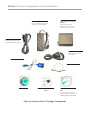
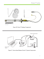
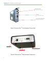
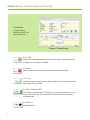
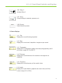
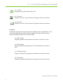
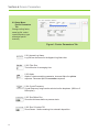
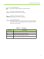
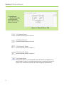
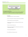
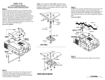
TM
NUCLEUS PLUS
PC-based film-thickness controller
user manual
TM
WARNING All electrical components are to be considered extremely
dangerous if tampered with in any way. Phillip Technologies is not liable for
any injury resulting from product misuse, modification, or disassembly.
WARRANTY LABEL If the warranty label has been tampered with, “VOID”
will appear where the warranty label was originally placed. If this is visible
at the time of arrival, it is important that you contact Phillip Technologies
immediately after receiving the product.
© Copyright 2014 Phillip
Technologies
All information contained within
this technical manual and
accompanying pages are copyright
of Phillip Technologies. All rights
reserved. It is a breach of copyright
if this technical manual is copied,
distributed, or reproduced, in
whole or part, using any means
whatsoever, without the prior written
approval of Phillip Technologies.
Phillip Technologies gives no
condition or warranty, expressed
or implied, about the fitness of this
technical manual or accompanying
hardware product. Phillip
Technologies reserves the right
to make changes to this technical
manual or accompanying hardware
or design without notice to any
person or company.
Phillip Technologies shall not be
liable for any indirect, special,
consequential or incidental
damages resulting from the use
of this technical manual or the
February 2014
Version 3.0
EXAMINE YOUR NEW NUCLEUS PLUS™ FOR ANY SIGNS OF
PHYSICAL DAMAGE. ALSO, ENSURE THAT THE TAMPER-EVIDENT
LABELS ARE INTACT Before shipping, your Nucleus Plus™ was
calibrated and tested by Phillip Technologies to meet the highest quality
standards. It is important that you take a few minutes to inspect the
product to ensure that your equipment was not damaged or otherwise
What Is the Nucleus Plus™ Thin-Film
About Nucleus Plus™
With the ability to sense deposition and temperature with high precision, the
Nucleus Plus™ thin film monitor is one of the newest advancements in Thin
Film deposition monitors. The Nucleus Plus™ provides features that help
improve measurement accuracy for better process monitoring.
LabVIEW® Interface
The Nucleus Plus™ offers a simple LabVIEW® interface that provides
control and operation that is intuitive, efficient, and impressive. The Nucleus
Plus™ is easy to set up right out of the box.
Software Updates
The Nucleus Plus™ interface software can be upgraded on site to provide
software improvements. There will be notifications when these updates
become available.
Inspection & Initial Setup
Examine Nucleus Plus™ for any signs of physical damage. Also, make sure
that the tamper-evident labels are intact. In order to ensure safe, correct
operation of your Nucleus Plus™, please follow the step-by-step instructions
presented in the Nucleus Plus™ Quick Start guide.
Warranty
Nucleus Plus™ is warranted to the original purchaser to be free of any
manufacturing-related defects for one year from the date of purchase.
Phillip Technologies reserves the right to repair or replace the unit after
inspection.
Contact [email protected] for more information.
ii
Contents
The Warranty Label........................................................................................................ i
Safety Information.......................................................................................................... i
Copyright........................................................................................................................ i
About Nucleus Plus™.........................................................................................................
ii
.....
ii
Software Updates........................................................................................................... ii
Inspection and Initial Setup.............................................................................................ii
Warranty.........................................................................................................................
Section 1: System Components and Connections
p. 1
1.0
Nucleus Plus™ Package
p. 2
Contents..................................................................
1.1
Proton™ System Components.............................................................
p. 4
Section 2: Hardware and Design
p. 4
2.0
Connecting Inputs...................................................................................
2.1
Connecting Outputs................................................................................
p. 5-6
Section 3: Front Panel Controls and Displays
p. 6-7
3.0
Controls.................................................................................................. p. 7
3.2
Status Displays.......................................................................................
3.3
Graphs....................................................................................................
p. 8-10
Section 4: Layer Controls/Selections
4.0
Setup Menu: Layer Tab..........................................................................
p. 11-12
Section 5: Process Controls/Selections
5.0
Setup Menu: Process Tab......................................................................
p. 13-14
Section 6: Device Parameters
6.0
Setup Menu: Device Parameters Tab.....................................................
p. 15
Section 7: Manual Power
7.0
Setup Menu: Manual Power Tab............................................................
p. 16
Section 8: First Start
p. 16
8.0
Communication Port Selection...............................................................
8.1
Procedure...............................................................................................
p. 17
Section 9: Using the Software
p. 17-18
9.0
Adding a Layer........................................................................................ p. 18
9.1
Adding a Process....................................................................................
9.2
Starting a Deposition...............................................................................
Contents
Section 10: Troubleshooting.......................................................................................... p. 19
Section 11: Specifications
11.0
Device Parameters................................................................................. p. 20
11.1
Deposition Settings................................................................................. p. 20
11.2
Measurement......................................................................................... p. 21
11.3
Process Display...................................................................................... p. 21
11.4
Communications..................................................................................... p. 21
11.5
Deposition Settings................................................................................. p. 22
Tables & Figures
Tables
1
2
3
4
5
6
7
8
Coating Specifications.................................................................................... p. 12
Troubleshooting.............................................................................................. p. 19
Device Specifications...................................................................................... p. 20
Coating Specifications..................................................................................... p. 20
Measurement Specifications........................................................................... p. 21
Process Display Specifications....................................................................... p. 21
Communication Specifications........................................................................ p. 21
Input and Output Specifications...................................................................... p. 22
Figures
A Nucleus Plus™ System
p. 1
Components......................................................................
p. 2
B Phoenix™ System Package Contents............................................................ p. 2
C Connections Between Phoenix System Components.................................... p. 3
D Nucleus Plus™ Front Hardware
p. 3
Connections..........................................................
p. 5
E Nucleus Plus™ Rear Hardware
p. 8
Connections...........................................................
p. 11
F Front Panel Controls and Displays................................................................. p. 13
G Layer Tab......................................................................................................... p. 15
H Process Tab..................................................................................................... p. 16
I Device Parameters Tab...................................................................................
J Manual Power Tab...........................................................................................
K Comport Selection Prompt..............................................................................
Section 1 System Components and Connections
Power Supply
Input: 100-200VAC, 50/60Hz, 2.0A
Output: 24V-3.75A, 90W MAX
Nucleus Plus™ Thin Film
Monitor
Nucleus Plus™ Monitor,
BNC Sensor Inputs, Type K
Thermocouple Inputs, Power
Power Supply Cable
North America standard plug
(Europlug available on request)
RS-232 Extension Cable
Standard, male-to-female
serial cable
USB to RS-232 Adaptor
BNC to Microdot Cable
Quartz Crystals
Nucleus Plus™ Quick Start
Guide
Nucleus Plus™ Software
Disc
Eon LT™ software, Labview
runtime, USB drivers, and manual.
Software requires administrative
Figure A: Nucleus Plus™ Package Components
Phoenix™ System
Phoenix Sensor Head
Phoenix™ temperature measuring
sensor head
Figure B: Proton™ Package Components
ProtonTM Sensor Head
substrate
source
shutter
Nucleus Plus
software
TM
Nucleus Plus
TM
Figure C: Connections Between Proton™ System Components
2
Section 2 Hardware and Design
BNC Sensor Inputs
For connecting to sensor head
Outputs
For relay and source outputs
Type K Thermocouple Inputs
For temperature measurement
Figure D: Nucleus Plus™ Front Hardware Connections
Power Input
24 VDC Power Input
LED Indicator
Variable Stat Indicator
RS-232
For connecting Nucleus Plus™
Figure E: Nucleus Plus™ Rear Hardware Connections
3
2.0 - 2.1 Connecting Inputs & Outputs
Nucleus Plus™ has been designed so that ONLY the correct hardware can
be plugged into the appropriate input or output. The following is a guideline
on how hardware should be connected in order to prevent damage to Nucle2.0 Connecting Inputs
There are four (4) inputs attached to Nucleus Plus™. It is important
that the correct hardware is used with these inputs (see Figure E).
2.0.1 Power
Only the provided power supply should be used with Nucleus
Plus™. Not doing so will cause hardware damage to Nucleus
Plus™ that will not be covered by warranty. Ensure that the
power supply has a 24 [VDC].
2.0.2 Comport
Connect an RS232 cable to this port. Always use the provided
USB to RS232 cable.
2.0.3 BNC
Nucleus Plus™ has a built in oscillator. (Phillip Technologies
also offers an external oscillator for purchase). The cable
between Nucleus Plus™ and the crystal should remain as short
as possible to avoid noise. The advisable maximum acceptable
length for this is one (1) foot or 30 [cm].
2.0.4 TC Connection
Nucleus Plus™ uses a thermocouple probe to measure the
temperature of the sensor head.
2.1 Connecting Output
There is one (1) output attached to Nucleus Plus™.
2.1.1 DB9 Connector
Connects the two SPST relays.
4
Section 3 Front Panel Controls and Displays
3.0 Controls
Change settings,
activate controls, and
halt process runs.
Figure F: Front Panel
3.0.1 Start
Initiates the selected deposition process. Each time a deposition process
is initiated, a new log file is created.
3.0.2 Abort
Manually cancels the deposition process and closes the log file
3.0.3 Log
Logs the current running process. New log files can be found on the hard
drive under “Eon Log” files.
3.0.4 Zero Thickness (ZT)
The interface contains three ZT buttons - one on each sensor tab (2) and
one on the control tab. The control tab ZT button zeroes both sensors
simultaneously.
3.0.5 Relay 1
Actuates Relay 1.
5
3.0 - 3.1 Front Panel Controls and Displays
3.0.6 Relay 2
Actuates Relay 2.
3.0.7 Setup
Change settings to materials, processes, etc.
3.0.8 Process
Select the active process
3.1 Status Displays
3.1.1 Film
Displays the current film being deposited.
3.1.2 Rate
Displays the current rate of deposition in angstroms per second.
3.1.3 Temperature
Displays the TC temperature reading numerically and graphically (the fill
bar covers a range of 0°C to 500°C).
3.1.4 Thickness
Displays the current thickness of the material in kilo-angstroms or
angstroms.
3.1.5 Frequency
Displays the current frequency of the crystal in hertz.
3.1.6 Health
Displays the crystal health in graphical and numeric form (the fill bar
covers a range of 0 to 100%).
6
3.1 - 3.2 Front Panel Displays and Graphs
3.1.7 Crystal
Displays if the crystal health is below 50%.
3.1.8 Source 1
Displays if Source 1 is active (above 0% power) for the current sensor.
3.1.9 Source 2
Displays if Source 2 is active (above 0% power) for the current sensor.
3.2 Graphs
These items represent the same values as the indicators, but in graphical form. Click
on the tabs (graph titles) to switch between graphs. During the run you have the
ability to change the scale of the x-axis and y-axis.
3.2.1 Rate Graph
Displays a graphical representation of the rate as a function of time*.
3.2.2 Temperature
Displays a graphical representation of TC temperature as a function of
time*.
3.2.3 Thickness Graph
Displays a graphical representation of thickness as a function of time*.
3.2.4 Frequency
Displays a graphical representation of frequency as a function of time*.
*Unit time is dependent on sample period
7
Section 4 Layer Controls/Selections
4.0 Setup Menu:
Layer Tab
Change layer
materials, display
material density,
and Z-Factor
Figure G: Layer Tab
4.0.1 Save Layer
Saves the deposition settings under a new layer named as stated.
4.0.2 Load Layer
Loads the layer name selected under the Layer Select dropdown menu.
4.0.3 Update Layer
Updates any changes to the selected layer.
4.0.4 Clear All Layers
Clears all of the saved layers.
4.0.5 Finish
Closes the Setup Menu.
4.0.6 Material
Dropdown option enables selection of the material being deposited.
4.0.7 Density
Density of the material to be deposited is automatically populated when a
material is selected. For custom densities, select “Custom” under material
and enter the desired density.
8
4.0 Layer Controls/Selections
4.0.8 Z-Factor
Z-Factor of Material 1. The field automatically populates with the value
selected under Material 1. The Z-Factor can be manually adjusted using
the dropdown arrows.
4.0.9 Proportional
Indicates the Proportional of the source.
4.0.10 Integral
Indicates the Integral of the source.
4.0.11 Derivative
Indicates the Derivative of the source.
4.0.12 Rise to Soak Time
Defines the rise to soak power in seconds.
4.0.13 Soak Time
Defines the amount of soak time in the soak power.
4.0.14 Soak Power
Defines Soak power.
4.0.15 Rise to Predeposit
Defines the Rise to Predeposit power in seconds.
4.0.16 Predeposit Time
Defines the amount of Predeposit Time in predeposit power.
4.0.17 Predeposit Power
Determines the Predeposit Power.
4.0.18 Tooling Factor
Selects the Tooling Factor for the material.
9
4.0 Layer Controls/Selections
4.0.19 Source Select
Select the source which will control the material deposition
4.0.20 Sensor Select
Select the sensor that will monitor the deposition.
4.0.21 Dwell Time
Select the time delay between the predeposit and automatic deposition.
This is useful when a shutter is used.
10
Section 5 Process Controls/Selections
5.0 Setup Menu:
Process Tab
Create a deposition
process. Multiple
layers (up to 10)
can be added in
sequence. Two layers
can be selected for
codeposition.
Figure H: Process Tab
5.0.1 Set Process Name
Enter a process name.
5.0.2 Process List
This list contains the current saved processes.
5.0.3 Save Process
When a new process name is entered, this button will be enabled to save a
new process.
5.0.4 Load Process
When a process is selected from the process list, this button will be
enabled to load the process. Processes are automatically loaded. If the
process is changed, press the Load Process button to reload the previous
settings.
5.0.5 Update Process
When the process has been changed, press the update process button to
save the changes
5.0.6 Clear Process List
This button deletes all of the saved processes.
11
5.0 Process Controls/Selections
5.0.7 Finish
This exits the setup window. Save any changing before pressing Finish.
5.0.8 Select Layer
Select the layer for the process
5.0.9 Process Type
Selected if user intends to add multiple layers.
5.0.10 Add layer
Adds the currently selected layer
5.0.11 Delete layer
Deletes the current “remove layer” number.
5.0.12 Remove layer
Selects the layer to be removed after pressing the “Delete Layer” button
5.0.13 Clear settings
Clears all of the currently active processes settings.
5.0.14 Layer
Displays the name of the layer to receive deposition.
5.0.15 Rate [A/s]
The target deposition rate for the active layer
5.0.16 Thickness [KA]
The target thickness for the active layer. (This field displays information
only and cannot be changed).
12
Section 6 Device Parameters
6.0 Setup Menu:
Device Parameters
Tab
Change tooling factor,
name log file, select
crystal frequency type,
and adjust period
manually
Figure I: Device Parameters Tab
6.0.1 Append Log Name
Log files can be named in the Append Log Name box.
6.0.2 Filter Size
The buffer size for averaging time
6.0.3 Alpha
Alpha is a data-smoothing parameter. Increase Alpha for quicker
response. Decrease Alpha for smoother response.
6.0.4 Crystal Frequency
Crystal frequency range can be selected on the dropdown (6MHz or 5
MHz option).
6.0.5 Zero Before Run
Zeros the thickness before a process starts.
6.0.6 Zero S1 before PID
Zeros Sensor 1 before entering into automatic deposition.
13
6.0 Device Parameters
6.0.7 Zero S2 before PID
Zeros Sensor 2 before entering into automatic deposition.
6.0.8 Relay 1: Operation mode for relay
Actuates Relay 1 (see Table 1 for functions)
6.0.9 Relay 2: Operation mode for relay
Actuates Relay 2 (see Table 1 for functions)
6.0.10 Update Parameters
Updates Nucleus Plus™ with any changes made in the Device Parameters
tab. In order to implement any changes to the device parameters, Update
Parameters must be selected.
Table 1 - Coating
Function
Description
Manual
No automatic action. The relay button must be pressed to actuate
Start
Triggers the relay when a process is started
After Predeposit
Triggers the relay after a predeposit is complete
Predeposit Trigger
Triggers the relay when the predeposit starts.
14
Section 7 Manual Power
7.0 Setup Menu:
Manual Power Tab
Change deposition
power manually using
Manual Power tab.
Figure J: Manual Power Tab
7.0.1 Manual Power 1
Enables manual power for Source 1.
7.0.2 Manual Power 2
Enables manual power for Source 2.
7.0.3 Source 1% Power
Sets the percent power for Source 1.
7.0.4 Source 2% Power
Sets the percent power for Source 2.
7.0.5 Update Power
Sets manual power. If left unselected, power will remain unchanged. As a
safety feature, if power is changed and the button is unselected, power will
return to 0%. Power also returns to 0% when exiting the setup window.
15
Section 8 First Start
Figure K: Comport Selection Prompt
8.0 Communication Port Selection
The COMPORT prompt will appear when you start the software for the first time. (Note: The
software will save your settings for future operations. The prompt will NOT appear during
subsequent starts. The COMPORT prompt, however, will re-appear if Nucleus Plus™ is
8.1 Procedure
1. Plug in the Nucleus Plus™ and all of its components
2. Open on the Nucleus Plus™ software and select the correct COMPORT
3. Click the Setup button and open the Setup Menu.
4. Select the material and make sure the Density and Z-Factor is correct
and save layer
5. Switch to the Device Parameters tab
6. Select the correct Crystal Frequency, Tooling Factor, and name the log
file, alpha values, and filter
7. Press the update parameters button.
8. Press FINISH when all changes are saved
16
Section 9 Using the Software
9.0 Adding a Layer
This guide will instruct on how to add a new layer to be used in the deposition process.
This is done from the “Layer” tab in the Setup window.
9.0.1
Enter the desired layer name in the “Layer Name” Field
9.0.2
Press the “Save Layer” button to save the new layer
9.0.3
Enter the desired information for the process.
9.0.4
Press “Update Layer” to save the changed settings.
9.0.5
Press “Finish” if there are no more changes to save.
9.1 Adding a Process
This guide will instruct on how to add a deposition process. This is done from the
“Process” tab in the Setup window.
9.1.1
Enter the desired process name in the “Set Process Name” field.
9.1.2
Press the “Save Process” button to save the new process.
9.1.3
Select the layer to be added under “Select Layer”
9.1.4
Select the process type under “Process Type”
9.1.5. If using codeposition, only 1 more layer will be available to be
added.
17
9.1.6
If using sequential, up to 10 layers will be available to be added.
9.1.7
Press “Add Layer” Button.
9.1 - 9.2 Software
9.1.8
In the “Rate [A/s]” Field for the newly added layer enter the target
rate for the deposition
9.1.9
In the “Thickness [K/A]” field for the newly added layer, enter the
target thickness for the deposition.
9.1.10 Repeat steps 9.1.2 to 9.1.7 to add more layers.
9.1.11 When all changes are saved, press “Finish” to exit the setup window.
9.2 Starting a Deposition
This guide will instruct on how to begin a deposition process. This action is performed
in the front panel. The setup window should not be open when starting a deposition.
9.2.1
Select the process to be deposited from the “Process” Selection
9.2.2
Ensure that the correct sensor tab is selected.
9.2.3
Press “Start” to start the deposition
9.2.4
If the processes needs to be aborted, press the “Abort” button.
9.2.5
Wait for the process to complete and the “Process Complete” window
to appear.
9.2.6
Repeat stops 9.2.1 to 9.2.6 to start other processes.
18
Section 10 Troubleshooting
Table 2 - Troubleshooting*
Symptom
Cause
Solution
Frequency reads -2.0 [Hz]
Sensor not detected
Check sensor connection
No information displayed
Wrong comport selected
Restart and select the
correct comport.
Rate reads -1
Improper settings
Restart software and
Nucleus Plus™
*If you cannot resolve an issue, please contact Phillip Technologies support at [email protected], or call (480)
19
Section 11 Specifications
11.0 Device Parameters
Table 3 - Device Parameters
Density
0.10 to 99.99 [g/cm3]
Z-Factor
0.00 to 15.00
11.1 Deposition Settings
Table 4 - Coating
Density
0.10 to 99.99 [g/cm3]
Z-Factor
0.00 to 15.00
Rate Setpoint
0.00 to 9999.99 [Å/s]
Thickness Set Point
0.00 to 9999.99 [KÅ]
Proportional Gain
0.00 to 999.99
Integral Time
0.00 to 999.99 [s]
Derivative Time
0.00 to 999.99 [s]
Rise to Soak
0.00 to 999.99 [s]
Soak Time
0.00 to 999.99 [s]
Soak Power
0.00 to 99.99 [%]
Rise to Predeposite
0.00 to 999.99 [s]
Predeposit Time
0.00 to 999.99 [s]
Predeposit Power
0.00 to 99.99 [%]
20
11.2 - 11.4 Specifications
11.2 Measurement
Table 5 - Measurement
Frequency Resolution
+/-0.002 [Hz]
Display Rate
10x to 1x per second
Crystal Frequency Range
5 or 6 [MHz]
Filter
0-1
Alpha
0-1
11.3 Display
Table 6 - Process Display
Film
Selected Material
Rate
0.00 to 99.9 [Å/s]
Thickness
0.00 to 999.9[KÅ]
Frequency
-3.00 to 6,500,000 [Hz]
Run Time
Hh/mm/ss
Temperature
0 to 999.9 [°C]
Health
0.00 to 100 [%]
11.4 Communications
Table 7 - Communications
Factory Set
21
RS-232 [PC version]
11.5 Specifications
11.5 Deposition Settings
Table 8 - Inputs and Outputs
Voltage input
24 [VDC]
RS232 Input
One Half Duplex
Sensor Input
Two BNC Connector
TC Output
2 Type K Connectors
0-5 [VDC] Control Output
Dual Relay Output
One DB9 Connector
22
End Manual
2003 Perimeter Rd / Suite E
Greenville, SC 29605
(864) 277-1560
[email protected]
[email protected]
TM