1
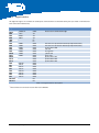
LED
V10
V9
V8
V7
Color
Red
Orange
Yellow
Green
Blackfin GPIO
PG8
PG9
PG10
PG11
Table 2-4: LED Description
2.3.4
GPIO Button
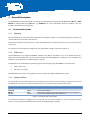
The four GPIO push-buttons are connected to Blackfin GPIOs of the SPM. They can be used to program a user
interaction. All buttons have a de-bouncing capacitor.
Button
S3
S3
S5
S6
Blackfin GPIO
PF15
PF14
PG14
PG7
Table 2-5: Push-Button Description
2.3.5
Reset Button
The Reset button ties the SPM Reset to GND. Also the Reset button is de-bounced by hardware.
2.3.6
DIP-Switch
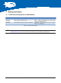
The DIP switch (S2) allows to disconnect the push-buttons from the GPIOs and to implement bootstrap
configurations.
Way
1
2
3
4
5
6
7
8
Blackfin GPIO
PG7
PG14
PF14
PF15
PG6
PG5
Not Connected
Not Connected
Function (ON State)
Connect to S6
Connect to S5
Connect to S4
Connect to S3
Tie PG6 to GND
Tie PG5 to GND
-
Table 2-6: DIP Switch Functionality
ADEV-BF52xC_HUM_V1.1.docx
14