1
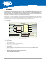
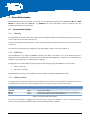
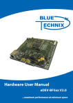
PCB Placement
DC-Plug
RESET Button
Mini USB-B
USB-B
Power source
selection
red
orange
yellow
green
Power LED
LEDs
2.2
Line Out
Mic In
Push-buttons
ACM-BF52xC
connectors
Line In
Headphone
Out
Configuration
Switch
On-board Mic
Figure 2-1: Board Layout
2.3
Switches, Jumpers and LEDs
The following section describes the Functionality of all jumpers switches and LEDs.
2.3.1
Power Source Selection Jumper
JP1
JP2, JP3
Power source
Comment
short
open
open
short
Board powered via USB connectors
Board powered via DC-plug
Power source for Core Module is 5.0V
Power source for Core Module is 3.3V
Table 2-3: Power source selection
2.3.2
Power LED
The green power LED indicates that a power source is plugged into the board.
2.3.3
GPIO LEDs
Four LEDs are connected to GPIOs of the SPM. They can be free programmed by the developer.
ADEV-BF52xC_HUM_V1.1.docx
13