1
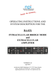
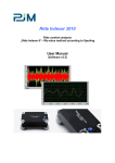
Equipment for Biomedical Research
Animal Behavior & Electrophysiology
Neurologger®
Synchronizer
User Manual
Evolocus LLC
August 2010
Table of Contents
1. Introduction ……………………………………………………....
2. Driver installation ………………………………………………..
3. Neurologger Synchronizer connections ……………………….....
3.1. Connection to USB ………………………………………….
3.2. Connection to the source of audio signal …………………....
3.3. Connection to TTL/CMOS line ……………………………..
3.4. Connection of IR emitters …………………………………..
4. Configuration of the Neurologger ……………………………….
5. Contact information and list of publications …………………….
3
4
5
5
6
7
7
8
9
2
1. Introduction
Neurologger Synchronizer is designed for synchronization of the “Neurologger 2”
and “Neurologger 2A” with the external equipment. Neurologgers are stand-along
systems that are able to record electrophysiological data in their internal memory
without any additional external equipment. After the end of experiment, the
gathered data can be downloaded in the computer with the help of special USB
adapter for further processing. However, in many cases it is desirable to have
precise time-stamps of certain events in the record. This can be some time labels of
audio/video or other type of stimulus, time of the beginning and the end of the
experimental session, and other similar time points. Putting such event labels is
possible with the help of IR-receiver add-on micro-board attached to the
Neurologger. This microboard also contains 3-D accelerometer to store
acceleration of the animal head (or a place where Neurologger is attached) together
with the electrophysiological record. Such record can help in some cases in
interpretation of the data. The IR-receiver micro-board received signal from the IR
emitter(s) attached usually somewhere at the top of the animal experimental cage
and directed to the animal location. The IR-emitters are controlled by the
Neurologger Synchronizer unit described in this manual. The Neurologger
Synchronizer is designed to receive signals from external equipment that can
provide a TTL /CMOS output or audio output. The Neurologger Synchronizer has
also USB interface and it can be attached to any computer with the USB port. In
software the device is visible as a serial port. Thus, the user can use any custom
written software capable to send data to the serial port of the computer to send time
labels to the Neurologger. Such software can be written in Matlab, LabView or
common programming languages like C and Delphi/Pascal. In the simplest case the
user can use Windows Terminal (or any other Terminal program) for making
labels. In this case each keystroke of the keyboard can be transmitted and stored in
the Neurologger and be precisely aligned with the neuronal data. If desired, several
animals carrying Neurologgers can be placed together in one experimental
chamber. In this case synchronizing labels from the Neurologger Synchronizer will
be written in all of them.
3
2. Driver installation
To use Neurologger Synchronizer with the TTL/CMOS trigging signal or audio output
no special software is needed. The software is needed only if the synchronization is
performed through the USB port of the device.
To use the Neurologger Synchronizer with the USB port one has to install first the
necessary USB driver. The FTDI interface chip is used in the Neurologger
Synchronizer. Thus, it is recommended to download and install the latest version of
the driver from the FTDI web site www.ftdichip.com. The drivers for this chip exist
for many operation systems, but we tested only under Windows. For this reason we
describe only installation in this operational system. Installation in other systems may
have small differences. If the user needs to work in the environment different from
Windows, we may address him to the FTDI web site for additional instructions.
Windows installation is described lower.
To install the FTDI USB adapter driver one has to run the installer
“CDM20802_Setup.exe”
that
can
be
downloaded
from
http://www.ftdichip.com/Drivers/D2XX.htm. Please choose the driver appropriate for
your OS. The most common driver is good for the following OSs:
Windows Server 2008 R2
Windows 7
Windows 7 x64
Windows Server 2008
Windows Server 2008 x64
Windows Vista
Windows Vista x64
Windows XP
Windows XP x64
Windows 2000
Windows Server 2003
Windows Server 2003 x64
The executable “CDM20802_Setup.exe” will install the driver without any additional
user intervention. If the installation goes without mistakes, no any messages will be
displayed.
4
3. Neurologger Synchronizer connections
3.1. Connection to USB
When the driver is installed the Neurologger Synchronizer can be physically attached
to the computer. This should be done only after the FTDI driver installation (described
in the paragraph “Driver installation”). If the driver is not installed before, the
Synchronizer may not be recognized properly. When the device is attached the first
time, a set of small pop-up windows will inform you that the new hardware is found.
First, you will be informed that the composite USB device DLP-2232PB is found.
Afterwards you will see the messages that the “USB Serial Converter A” and “USB
serial Converter B” are found. And at the end, that “USB Serial Port” is found.
You can verify the correctness of the driver installation in the Windows Device
Manager. Two additional USB devices “USB Serial Converter A” and “USB serial
Converter B” and the new “USB Serial Port (COMn)”should be visible.
If the port number does not look convenient, it can be changed in properties of
the serial port (“Port settings” ->“Advanced”). This port number should be specified
in the user software that will access this port.
5
It is important to note that this is a “virtual” serial port. For this reason parameters
such as communication speed and parity are not important for communication. Any
values can be specified in the user software (Windows Terminal, for instance).
Parameters 19200bps, 1 start bit, 8 data bits and 1 stop bit without parity work fine.
The hardware flow control should be disabled.
3.2.
Connection to the source of audio signal
The Neurologger Synchronizer has one audio input socket and one audio output
socket. Both accommodate a standard 3.5 mm audio jack. Input and output are clearly
labeled on the device:
The idea of using input-output is the following. If we have to present an audio cue to
the animal, we can use one channel from two stereo outputs for this task. We have
selected the “Right” channel for audio cue. In accordance with international
agreement, the “Right” channel is connected to the middle contact of the 3.5-mm
audio jack and the “Left” channel – to its tip. Inside Synchronizer signal goes directly
from the “Right” “Audio IN” to the “Left” “Audio OUT” (for compatibility with
mono equipment). The “Left” channel of the “Audio IN” (at its tip) can transmit the
synchronization signal that will make “flash” of the IR transmitting diodes to store this
event in the Neurologger. Just one pulse of any duration (that can go through the audio
cascade) is sufficient for recognition by the Synchronizer. The proper stereo audio file
can be generated in Sound Forge or Matlab. The synchronizer has a built-in amplifier
and a signal of usual loudness can be detected. When the trigger is detected, the LED
6
“Signal” flashes on the device. Both sources, USB and Audio IN can be used at the
same time, but for proper signal separation a small time interval should be present
between any pair of trigging events. The duration of this interval should not be less
than the period of sampling of electrophysiological signal. For instance, if the
Neurologger is configured for sampling at frequency 400 Hz, the inter-stimulus
interval should be larger than 2.5 ms. Better – larger than 5 ms for reliability in the
case of short stimuli. However, if stimuli are long (for instance – long bursts), this
time gap should be kept between the end of the previous stimulus and the beginning of
the next. If the setup is complicated and stimuli from several sources are desirable,
one may think about coding of a single event by several pulses to discriminate stimuli
of different nature in the record.
3.3.
Connection to TTL/CMOS line
If desired, the synchronizing TTL/CMOS output of external equipment should be
connected to the “Audio IN” socket. Signal ground should be connected to the audio
“Ground” of 3.5-mm audio jack (the closest to the cord contact) and the signal itself
should be connected to the middle contact of this jack. The synchronizing IR pulse
will be sent at the rising edge of the TTL/CMOS pulse. The maximal frequency of
synchronizing pulses should not exceed 1900Hz in a burst, and the burst duration
should not exceed 255 pulses. The maximal number of pulses in a burst is usually not
a limiting factor, as normally the amount of different events to be coded is small
(usually – one or several). And they can be coded by small amount of pulses. In highfrequency neuronal mode of the Neurologger (9600 Hz) the pulses will be stored in
the data at times exactly when they came. However, when the sampling rate is low
(1600 Hz or lower), information about the event will be written in the coded form after
termination of the burst. This usually does not make a problem, as bursts are usually
short in time and with low sampling rate there is no need to have a very precise
synchronization (at ms scale) in any case.
3.4.
Connection of IR emitters
Two IR emitters are provided with each device and one or, better, both of them should
be used for the signal transmission to the Neurologger. The emitters have 3.5-mm
mono audio jacks that should be plugged in the sockets labeled “IR LED OUTs (2x)”.
The half-intensity emission angle of the diodes is ±17°. They should be directed to the
area where the investigated animal is. The receiver is quite sensitive to detect the
reflected signal from the walls or other objects, if animal went out from the area of the
direct illumination. High sensitivity of the receiver and good engineering of the
system in general allows work even with strong background IR illumination. Such
illumination, produced by IR illuminating panels of IR video cameras, is not usually a
problem for transmission of the synchronizing signal. For instance, Neurologger
7
Synchronizer works well in the popular Phenotyper from Noldus. Ambient
illumination is not a problem in most cases too. However, most probably the system
will not work well under the direct sunlight. If IR background illumination is used,
and if the animal changes its position fast, false-positive detections can appear in the
record. In such cases it is recommended to code the event of interest by several pulses
and filter this sequence from the record. The last is usually done in Matlab. If this
approach does not work satisfactorily, or is the background IR illumination is very
strong, one can interrupt the background illumination for a short period (usually –
several ms) to transmit the synchronizing pulse. To do this one should direct the
ground (negative) line of the IR emitting panel though the jack of the Neurologger
Synchronizer labeled “SW to GND (max: 30V, 13A)”. The central line should go to
the negative contact of the LED panel and the peripheral contact should be connected
to the ground (or negative terminal) of the IR emitting panel power source. Note:
some versions of Neurologger Synchronizer do not have this “SW to GND” socket.
When the background IR light switching is used, there is no need to attach emitting
LEDs to “IR LED OUTs (2x)” as the background light itself will be interrupted in a
way to transmit the signal. This will work only if the IR emitting panel is built from
the IR diodes without any additional circuitry (smoothing capacitors, etc.).
4. Configuration of the Neurologger
The Neurologger should be configured properly to communicate with the add-on
IR/accelerometer micro-board. To do this one should use Downloader.exe utility
described in the Neurologger User Manual. One should select the checkbox
“Accelerometer/IR board present” and the checkbox “IR stored”:
8
Afterwards one should not forget to write new configuration in the logger pressing the
button “Set sampling options”. After recording session, when converting the data into
text or floating point binary format, don’t forget to select the checkbox “Add markers
to the Text/Float32IE file” to store synchronization labels in a separate column.
5. Contact information and list of publications
Please contact Evolocus LLC in order to purchase Neurologger Synchronizer:
Evolocus LLC
177 White Plains Road, 42B
Tarrytown, NY 10591, USA
Tel: +1 (914) 329-0035
Fax: +1 (914) 631-3421
E-mail: [email protected]
Web: www.evolocus.com
The following publications were done with the Neurologger:
1. Rattenborg N.C., Voirin B., Vyssotski A.L., Kays R.W., Spoelstra K.,
Kuemmeth F., Heidrich W.,and Wikelski M. (2008) Sleeping outside the box:
electroencephalographic measures of sleep in sloths inhabiting a rainforest.
Biol. Lett. 4(4):402-5.
2. Vyssotski A.L., Dell'
Omo G., Dell'
Ariccia G., Abramchuk A.N., Serkov A.N.,
Latanov A.V., Loizzo A., Wolfer D.P., Lipp H.-P. (2009) EEG responses to
visual landmarks in flying pigeons. Curr. Biol. 19(14):1159-66.
3. Pang D.S., Robledo C.J., Carr D.C., Gent T.C., Vyssotski A.L., Caley A,
Zecharia A., Wisden W., Brickley S.G., and Frank N.P. (2009) An unexpected
role for TASK-3 potassium channels in network oscillations with implications
for sleep mechanisms and anesthetic action. Proc. Natl. Acad. Sci. USA
106(41):17546-51.
4. Brankack J., Kukushka V.I., Vyssotski A.L., and Draguhn A. (2010) EEG
gamma frequency and sleep-wake scoring in mice: Comparing two types of
supervised classifiers. Brain Res. 1322: 59-71.
9