1
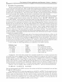
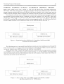
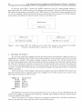
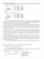
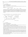
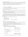
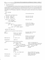
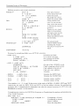
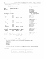
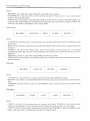
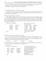
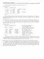
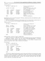
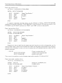
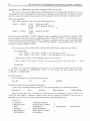
Vectoring Arrays of Structures
Rieks Joosten
Stale Universily of Ulrechl
LaboralOryfor Experimemal Physics
PrincelOnplein 5
Ulrechl
lhe Ne1herlands
Hans Nieuwenhuyzen
Slerrell'ac!ll "Sonnenborgh"
Zonnehurg 2
Ulrechl
lhe Nelherlands
Abstract
Writing a program module requires the specification of the interface between this and other
program modules (or the operating environment). Since modularity implies that you can
replace one module by another. a mechanism is needed to switch the definitions (datastructures)
that make up the program module interface. In this paper. a general way of switching the action
of a set of Forth datastructures (which can be thought of as a program module interface) is
presented.
Introduction
It is shown that software can be designed in a structured way. e.g. for switching hardware
oriented drivers. Switching drivers can now be done in a very general and safe way. A general
framework is defined. which is the (virtual) interface between the hardware driver and user software.
When an actual driver is attached to this framework. its routines (fields) will be called by the user
(program) through the VI (Virtual Interface).
Drivers generally need some special action before they can be used (e.g. initialization of
hardware). or before they can be de-assigned (e.g. turning off power). The syntax allows such
actions to be specified when defining the actual drivers. An example is given of a character II 0
system. and a possible implementation is given based on FysForth vsn 0.3.
The technique can be used whenever a vector of routines is used. and when the complete
(execution) vector needs to be switched.
In section I. we describe a mechanism for interfacing between modules. using a block system
built on different mass storage drivers as an example. In the second section we will deal in a more
general way with problems that may occur. showing some examples of the syntax for building the
structures that are introduced in the first chapter. Sections 3 through 5 deal with the syntax and
semantics of all relevant structures in detail. The implementation used is given in section 6: section 7
shows the internal structure of the words that are built. After several examples in section 8. we
discuss performance and tradeoffs. For those who are not familiar with the system on which the
described mechanism is implemented, Appendix A gives the deviations from the used system with
respect to the Forth '79 Standard.
The Journal of Forth Application and Research Vol. I. Number 2. Dec. 1983.
35
The Journal of Forth Application and Research. Volume l. Number 2
36
1. Modular Programming
Modular programming is a programming technique that allows multiple programmers to work
on the same job at the same time. This is achieved by assigning each programmer a part of the job.
called a module. A detailed specification of the constraints to which the programmer has to work is
provided: the interface between the module of his program and other defined modules. Therefore.
modules have to be specified (e.g. what actions they can take). and the interfaces between modules
have to be specified ,ince modules must be able to communicate with other modules.
Forth system software includes chunks of software that could readily be written in terms of
modules. As an example. let us see how one could write the 'block' words using program modules.
A block system contains among others the following words: 'BLOCK'. 'BUFFER'. and
'SA VE-BU FFERS'. These words use some kind of mass storage organization that is not important
to a user: as long as he can efficiently use all the mass storage media that he wants to use. he may not
be interested in the organization of blocks on the mass storage medium. When a system has to use
different devices at the same time. there are some problems. like: 'How does the block system know
which mass storage device is in use', and 'How does it know how to read from or write to this device~'
Here. modular programming can help you. Assume a mass storage program module that
contains definitions that allow you to read a block from a mass storage device, write a block to it.
etc. Now. some way to link both modules is needed: the module interface. The module interface
contains a specification of the definitions the block system program module wants to use. but does
not have available. The module interface should describe what definitions must be part of the mass
storage driver program module.
Some kind of structure. being the equivalent of the module interface description. will have to be
present in the block system program module so that you can define the whole of this module without
having to worry about how the actual mass storage handling words are put together. This structure
is called the 'Virtual !Hass Storage Interface' (VMSI) structure. and contains the specifications of
the actions that can be taken by a mass storage driver. The driver cannot do anything specific unless
actual actions have been assigned to each of the words specified by this structure,
In the example. the following definitions are specified in the VMSI structure:
Definition type:
VARIABLE
CONSTANT
or CODE
or CODE
"
or CODE. . . . . . . . . . ..
Name:
ERRIt
LItDEV
BREAD
BWRITE
RESET
Description:
. Error specifying number
. Nr. of blocks on the device
. Read a block from the device
. Write a block to the device
. Reset the de\ice
Analogously. the actual mass storage driver program module has to contain a structure that
will enable the correct coupling of the actual mass storage driver program with the block system
program module. i.e. the V MS I structure. This structure (in the actual mass storage d river program
module) will be called the 'Actual Mass Storage Interface' (AMSI) structure. So we have a VMS I
and an AMSI that ha\'e to work together in actual use; together they can be thought of as being the
interface between two modules. (The AMSI and VMSI structures are specific examples of the Al
(Actual Interface) structure and the VI (Virtual Interface) structure. that will be introduced later}.
Suppose we have available a mass storage device called DA:. and the following definitions:
DA:BREAD
DA:BWRITE
DA:RESET
that are incorporated in the AMSI structure: the routines in the block system module can use them
through the VMS I structure.
Nowsuppose we have two mass storage devices. called DA: and DB:, The documentation that
is supplied with these devices gives all the information needed to write the routines that read from.
write to. and reset these devices. We also need to create a constant that contains the maximum
number of blocks that fit on these devices. to create a variable that can be used by the read- and write
routines to store error conditions into, For the purpose of the example. we will assume that the
abO\'e definitions are also available for DB:. so now we have:
Vectoring Arrays of Structures
DA:BREAD
DA:BWRITE
37
DA:RESET
and DB:BREAD
DB:BWRITE
DB:RESET
which read a block from. "irite a block to. and reset the devices DA: and DB: respectively.
Obviously. both mass storage driver program modules will have an AMSI structure. The block
system program module does not know which of the above modules it uses. since it only sees the
VMSI structure through which it accesses the routines from the currently active AMSI structure.
Switching the currently active AMSI structure ensures that the block system program will from
that moment on use another device. Suppose we have the routines 'DA:' and 'DB:' which will
allocate the AMSI structure of the DA: or the DB: module respectively. First. after having loaded
both the DA: and the DB: module and the block system program module. the VMSI from the block
system progam module is not attached to either of the AMSI structures (see Fig. 1.)
Blocksystem
VMSI-struct.
.
.--------,._-------------------------_._------,---_.--_.
,
:
AMSI-struct.
~
-
~
. ....,... - - -
-----_. --_. ---------_.. ------- ---------,
-;-
AMSI-struct.
:
._-----------------------------------.
DB: MS-driver module
DA: MS-driver module
Figure 1. Organization after definition of all modules: VMSI and AMSI
structures are not attached.
If at t his time you try to use words from the block system. an error condition exists. because the
block system words try to access some mass storage device through the V M SI structure which in its
turn is not linked to any AMSI structure: the interface is incomplete.
When the word 'DA:' is typed. the AMSI structure of the DA: mass storage module is attached
to the VMSI structure of the block systems module (see Fig. 2.). At this moment. executing words
from the block system will use the definitions from the DA: module. which means that blocks are
read from and written to the DA: device.
...
...
,-------------_ ..... _--------------------------------,
Blocksystem
VMS I-struct.
:----------~ - -. -------- --;- ---- . --. ----------'. ---------,
--_.--_._-.-.-.---------------.-
··
...
--_.---------------------------------_.-----,
AM S I-struct.
DA: MS-driver module
:. - - - - - - j - - - - -- - - - - - - - - - - - - - - - - - - - - - - - - - _. _.
AMSI-struct.
DB: MS-driver module
Figure 2. After typing 'DA:'. the AMSI-structure of the DA: module
has been attached to the VMSI-struct.
- -- -- - - - --
38
The Journal of Forth Application and Research. Volume L Number 2
If now the word 'DB:' is typed. the AMSI structure of the DA: mass storage module is
de-coupled from the V MS I structure of the block systems module. Then the A MS I structure of the
DB: mass storage module is attached to the VMSI structure of the block systems module (see Fig.
3.). At this moment. definitions from the block system will use the routines of the DB: module.
which means that blocks are read from and written to the DB: device.
Blocksystem
VMSI-struct.
AMSI-struct.
AMSI-struct.
DA: MS-driver module
DB: MS-driver module
Figure 3. After typing 'DB:'. the AMSI-structure of the DA: module is de-coupled. The AMSIstructure of module DB: is attached to the VMSI structure.
2. Jvfodular Intel/aces
We will now extend the example from the previous section and introduce a general syntax for
interfacing two modules. One of these is the master module: it uses routines from the other module
called the slave module. The master module contains the structure (the Virtual Interface (VI)
structure) that specifies what routines should be in the slave module. and what these routines should
do. The slave module also contains a structure (the Actual Interface (AI) structure). that takes care
of the correct attaching of the slave to the master module. (N ote that VI structure is the general
structure. of which the VMSI structure was a specific example: the same holds for the AI and the
AMSI structures).
The VI structures of the example of the previous chapter can now be defined. We assume here
that the routines that are densely printed are available in the Forth system. See sections 3 and
following for discussion of these words.
VIRTUAL
SVAR
SCONS
SEXEC
SEXEC
SEXEC
END
MS-DEVICE
ERR!!
L!!DEV
BREAD
BWRITE
RESET
The definition of this VI structure specifies that an AI structure of type MS-DEVICE will
consist offive fields. of which the first will act as a variable. the second as a constant. and the others
as an executable Forth routine.
The AI structures for the mass storage driver program modules DA: and DB: are defined as
follows. provided the words used are known to the Forth system.
Vectoring Arrays of Structures
ACTUAL
MS-DEVICE
0
2002
DA:BREAD
CFA
DA:BWRITE
CFA
, DA:RESET
CFA
39
DA:
INIT
INIT
INIT
INIT
INIT
ERR#
L#DEV
BREAD
BWRITE
RESET
END
ACTUAL
MS-DEVICE
0
2002
DB:BREAD
CFA
, DB:BWRITE
CFA
DB:RESET
CFA
DB:
INIT
INIT
INIT
INIT
INIT
ERR#
L#DEV
BREAD
BWRITE
RESET
END
This syntax has been chosen to help in defining the actions. Specifying syntax and semantics of
words that together make up some concept takes careful analysis of what is going on. and what it
really is that you want. This syntax may seem difficult at first because at first sight it does not
resemble Forth. However. it was defined to do what it has been told to.
A few situations need careful analysis when installing or using this techniq ue. If a master
module is not attached to a slave module. (i.e. there is no currently active AI structure). execution of
a word in the master module that uses any routine of the slave module. generates an error condition.
Executing the word that attaches the slave module to the master module is essential for correct
operation of the module.
Whenever a slave mod ule is being attached to a master module. some initialization of the sian
module can take place. e.g. when a disk driver module is attached to a block system module. the
specified disk drive should be reset. This can be done by executing an 'OPEN' routine immediately
after the coupling has been completed. Analogously. before de-coupling a slave module from a
master module. some 'CLOS E' action may take place (e.g. by turning off the power of a device that
consumes a lot of power).
Since there is no reason why a master or a slave module should be loaded before the other. this
may give rise to 'forward references'. The system should take care that any currently active AI
structure is properly 'CLOSED' and de-coupled when it is forgotten: if not. execution of routines
from the master module may cause a system crash. This is a feature that most Forth systems cannot
provide. However. the given implementation on the FysForth system does allow this. because it has
a specific 'FORGET' action (ref. [2]).
The difficult part when using this technique is to find the correct set of interfacing routines.
3. Syntax and Semantics oj the Virtual Intel/ace Structures
There are two phases in defining interface structures:
I. define a Virtual Interface (VI) structure and
2. define an Actual Interface (AI) structure. together with the optional initialization of its fields.
We define the general syntax of a virtual structure:
VIRTUAL
<n>*[
END
<SWORD>
<virtstruct>
<field name>
]
Start the structure
(Define the framework).
Specify the fields
in the framework.
End of structure
The Journal of Forth Application and Research, Volume I. Number 2
40
where:
-
[ .... ] is optional,
< word > is a symbolic name.
capital letters are existing names.
<n>*[ .... ] denotes that [ .... ] occurs <n> times.
<virtstruct> is the name of the routine that contains the general specification of structures of its
type.
- <SWORD> is one of the following types:
SCaNS
$VALUE
$VAR
$TEXT
SEXEC
Note that the words of type <$WOR D> create Forth routines that act on the data in the respective
field of the current actual structure. If there is no currently defined structure. an error occurs. How
the routines act on the data in the current actual structure depends on how they were specified at
creation time of <SWORD>. Additional routines of type <SWORD> can always be created.
- <field name> corresponds to the routine that acts on the contents of a named field in an actual
structure.
4. Syntax and Semantics of the Actual Interface Structures
ACTUAL
<virtstruct>
OPEN>
CLOSE>
<actualname>
<open routine> ]
<close routine> ]
<m>*[ <p>*[
INIT"
<q>*[ <number> INIT
Start the structure
Init. open-action
lnit. close-action
<fld. name"> "<text>" ]
<field name>
]
Initialization of (some of the) defined fields.
END
End of structure
where:
-
-
-
[ .... ] is optional.
< word> is a symbolic name.
capital letters are existing names.
<n>*[ .... ] denotes that [ .... ] occurs <n> times.
<virtstruct> is the name of the routine that contains the general specification of structures of its
type. (see the definition of <virtstruct> on the previous page).
<actualname> is the name of the routine that will 'close' the current structure of type <\'irtstruct>
(i.e. finish). make itself current. and 'open' the current structure of type <virtstruct> (i.e. itself).
OPEN> is the routine that assigns an <open routine>(which is the name ofa Forth routine) to the
general open routine for the actual structure <actualname>. The open routine for an actual
structure is executed as soon as that actual structure is made the current one. Such routines handle
the needed initialization.
CLOSE> is the routine that assigns a <close routine> to the general close routine for the actual
structure <actual name>. The close routine for an actual structure is executed as soon as that
actual structure is released from the current structure. This can be achieved by assigning another
actual structure as the current one (or by Fa RG ETing the act ual structure that happens to be the
current one. assuming that FORGET is able to do such (see ref. [2] ). Routines such as the
<close routine> handle finalization.
INIT" initializes the named field <fld.name"> using the string following the field name. This string
should be delimited by quotes.
41
Vectoring Arrays of Structures
- <number> symbolizes Forth words and or numbers that put one number on the stack. Example:
2002 returns a valid number. as well as the sequence: ' DEPTH CFA 2*
- INIT initializes the named field <fieldname> using the number on top of the stack.
5. Action of the <$ WORD>s
The routines of type <SWORD> take care of the type of the fields in both virtual and actual
structures. These routines have to contain information about:
- the length of the field (in bytes).
- the execution of the routines assigned to the field «fieldname». that will act on the data in that
field.
- the initialization procedure INIT" on that same field. given the data storage address of the field on
top of the stack. and a text in the inputbuffer.
- the initialization procedure of INIT on that same field. given a number 2nd on the stack and the
data storage address of the field on top of the stack.
Note that two initialization routines are to be specified. An example of the necessity of this is
when a STEXT-field is to be initialized: it is possible that the address of the string that is to be
assigned to the STEXT-field is on the stack (in which case INIT would be used). whereas the text can
also still in the input buffer. in which case INIT" will take care for the proper initialization of the
STEXT-field.
Creating routines of type <SWORD> is done as follows:
<length of field>
<cfa of <init> routine>
<cfa of <init"> routine>
<cfa of exec routine>
SWORD
<SWORDname>
where
- <length of field> is the length of the field (in bytes).
- <cfa of <in it> routine> is the cfa of the routine that initializes the field starting at the address given
on top of the stack. using the number 2nd on the stack.
- <cfa of <init"> routine> is the cfa of the routine that initializes the field at the address on top of the
stack. given a string in the inputstream (the string is delimited with quotes).
- <cfa of exec routine> is the cfa of the Forth routine that acts on the contents of the address that is
on the top of the stack.
- <SWORDname> is the name of the new <SWORD>.
Example of creating SWORDS: definition of STEXT.
2
Length of a STEXT-field
CFA
push cfa of IN IT-routine
:ORPHAN HERE SWAP!
&" WORD C@ 1+ ALLOT:
push cfa of INIT"-routine
:ORPHAN @ ?DUP
IF COUNT TYPE
THEN:
push cfa of DO-routine
SWORD STEXT
Create a new word of type
SWORD with name STEXT.
The word :ORPHAN is not standard: see Appendix A for its explanation.
The Journal of Forth Application and Research. Volume L Number 2
42
6. Implementation
The implementation of the described structures has been done in FysForth vsn 0.3. This Forth
system uses the TO-concept [I]. and some defining words (which also solve some problems with
forgetting) [2]. For system dependencies we refer to the FysForth vsns 0.2 0.3 User Manual [3]. The
following code implements the described structures. Some routines use the reference word set as
appended to the '79 standard. Appendix A of this paper contains a description of non standard
words.
RIX 19830301
Set hexadecimal base
HEX
Helpvariables and helproutines
o
o
o
VALUE
VALUE
VALUE
VIRTfACT
VADDR
STRUCLEN
See [I] for VALUE
Generate VALUEs.
: SINIS 0 TO VIRT! ACT
o TO VADDR
o TO STRUCLEN
Reset the values
=VIRT ACT?
VIRT ACT <>
IF
CR." "SYNTAX ERROR"
." ": VIRT ACT = "
VIRT ACT. SINIS ABORT
THEN:
Test for the wanted
structure type: ABORT
if the wrong structure
is found .
@EXEC @ EXECUTE
Defining word for general (virtual) interface
DO>
BUILD>
HERE TO VADDR
I TO VIRT ACT
o TO STRUCLEN
o
o
PRE-BUILD>
o =VIRT
DEFWORD>
VIRTUAL
ACT?
See [2] for DO>, BUILD>
PRE-BUILD> etc.
Pointer to current struct
Total structure length
Check validity before
building the Virtual.
Defining word for Fields in general interfaces
DO>
BUILD>
PRE-BUILD>
DEFWORD>
DUP @ @ ?DUP
<PFA~<CURSTRUCT>
IF
OVER 2+ @ +
<PFA>,<CURSTRUCT+OFFSET>
SWAP 4 + @ @EXEC
<CURSTRUCT+OFFSET> is on
ELSE NFA COUNT 3F AND STYPE
top of the stack
." " NOT ASSIGNED. "
Abort when not
ABORT
assigned.
THEN
VADDR.
STRUCLEN
DUP,
6 + @ +TO STRUCLEN
Adjust STRUCLEN with the
length field of type <SWORD>
Check validity before
I =VIRT ACT?
building the Field.
FIELD
43
Vectoring Arrays of Structures
Defining word for real (actual) interfaces
FORGET>
DUP >S
6+S@@=
IF
S 4 + @EXEC
oS @ !
THEN -S
DUP >S @ @ ?DUP
IF
2- @EXEC
THEN
SOUP 6 + SWAP @
S> 2+ @EXEC
DUP
DO>
BUILD>
Save pfa of actual.
Is this actual current?
Close the actual.
De-assign the virtual.
Clean up system stack.
Close current structure if it was current:
then switch the actual
to become the current
structure.
Pointer to virt. struct
Addr's of the default
real open; close words.
Save the field-addr
Erase and allocate memo
for the fields.
o.
o.
HERE TO VADDR
2+ @
HERE OVER ERASE
ALLOT
2 TO VIRT; ACT
0 =VIRT ACT?
PRE-BUILD>
Set actual mode.
Check validity before
building the Actual
Put pfa of virtual on the
stack.
[COMPILE] ,
DEFWORD>
ACTUAL
Routines for initializing fields in an ACTUAL structure
(OPN CLS)
2 =VIRT; ACT?
[COMPILE] , CFA
SWAP VADDR + !
Initializes the fields
in an actual structure
that contain the OPEN
and CLOSE routines.
(INT) 2 =VIRT; ACT?
[COMPILE] ,
DUP @ VADDR 6 - @ ?PAIRS
DUP 2+ @ VADDR +
ROT ROT
4 + @ + @EXEC :
Get pfa of the <FIELD> word.
Check congruence field actual.
Calc. address to be init.ed.
Calc. init. exec. address.
Initialize.
OPEN>
CLOSE>
Initialize the OPEN field.
Initialize the CLOSE field.
INIT
INIT"
-4 (OPN CLS)
-2 (OPN CLS)
4
2
(INT)
(INT)
Initialize using a number.
Initialize using a string.
The numbers (-4, -2, 4 and 2) that occur in the code of OPEN> CLOSE> INIT and INIT"
respectively are used by (OPN CLS) and (INT) to find an address relevant for initialization
purposes: this is implementation dependent (see also the internal structure of ACTUALs and
$WORDS in section 7 of this article).
Completing the creation of a VI RTU A L Structure or Completing the creation and initialization
of an Actual Structure.
END VIRT ACT
DOCASE I CASE STRUCLEN VADDR 2+
ELSE 2 CASE
ELSE
ABORT
ENDCASE SINIS :
Completing a Virtual
Completing an Actual
Abort if neither
Reset the helpvalues
The Journal of Forth Application and Research. Volume I. Number 2
44
SWORDs (Fields specification words)
NO"
CR." "Wrong syntax used"
ABORT:
DO>
BUILD>
Generate a syntax error
message.
[COMPILE] FIELD
DO-routine.
INIT"-routine.
IN IT-routine.
Length of field in an
ACTU A L structure.
DEFWORD> SWORD
=2
SWORD SCONS
Length of field
INIT-routine
INIT"-routine
DO-routine
=2
SWORD SVAR
Length of field
INIT-routine
INIT"-routine
DO-routine
=2
SWORD SVALUE
Length of field
INIT-routine
INIT"-routine
DO-routine
=2
:ORPHAN -FIND 0= 4 ?ERROR CFA SWAP
, @EXEC
CFA
SWORD SEXEC
Length of field
INIT-routine
INIT"-routine
DO-routine
Length of field
IN IT-routine
INIT"-routine
DO-routine
=2
2
, !
, NO"
'@
CFA
CFA
CFA
2
,
I
CFA
CFA
CFA
, NO"
, EXIT
2
, !
, NO"
EXECTO
CFA
CFA
CFA
2
,
CFA
I
2
CFA
:ORPHAN HERE SWAP! &" WORD C@ 1+ ALLOT
:ORPHAN @ ?DUP IF COUNT TYPE THEN
SWORD STEXT
,
I
7. Internal Structure of Words That Are Built
This section describes the internal structure of the following word types:
<VIRTUAL>
<ACTUAL>
<FIELD>
<SWORD>
Note: within each type. every field is 2 bytes long. unless explicitly specified otherwise.
VIRTUALs
~
HEADER
------_. --------------------------------------------CURSTRUCT
STRUCLEN
----------------------------,--------------------------
Vectoring Arrays of Structures
45
where:
- HEADER is the link field. name field and code field of the routine:
- CURSTRUCT is the pfa of the current actual structure: if this value is O. no current actual
structure has been allocated.
- STRUCLEN is the length of the parameterfield of an ACTUAL routine of this VIRTUAL type
(in bytes). Since this length can only be known at the end of the creation of a complete VIRTU AL
structure. this field is initialized by the routine END.
ACTUALs
HEADER:
,~
.
fI
VIRTUAL
:
OPEN
CLOSE
FIELDS
. ,
.
,
•••• - - - - - - - - - - - - - - - - - - - - - - - - - - - - - - - - - - - - - - - - - - - - - - - - - - - - - - - - - - - - - - - - - - - - - - - - - - - - - - - - _. - - - - - - - - - - - - - - - - - _.1
where:
-
-
-
fI VI R TU AL is the pfa of the virtual structure that was used when this routine was defined (using
ACTUAL);
OPEN is the cfa of the routine that is executed immediately after this structure is made the current
structure:
CLOSE is the cfa of the routine that. when this structure is the current one. is executed
immediately before this structure is de-assigned as the current one or when this structure is to be
forgotten;
FIELDS is a memory area with length STRUCLEN bytes. where
STR UCLEN is the contents of the second field of the virtual structure that was used to define this
actual structure.
FIELDs
···
·
....
:
.--------------------------------------------------------------------------------------------,
HEADER
fI
VIRTUAL
OFFSET
SWORD
fI
.
:
.
,--------------.-----------------------------------------------------.-.-------------------.-,
where:
- fI VIRTUAL is the pfa of the virtual structure that has been defined the latest:
- OFFSET is the offset in the field FIELDS within the actual structure where this routine finds its
data:
- flSWORD is the pfa of the routine (of type SWORD) that was used to create the routine of type
FIELD.
$WORDs
i
HEADER
i
fI
EXEC
fI
IN IT"
fI
INIT
LENGTH
.-- - ----- - - - - - - - - - - - - - _. - _ .. - -- --- -- ---- - - -- - - -.-.- -.- -- ---- -- ---- -- - - -- --.- --- - -- -- -- - - - - - - - - -- ,
I
,
,
•
,
-
- - - - - -,
where:
EXEC is the cfa of the routine that acts on data in the field FIELDS of the current actual
structure: the address of where this data can be found should be on the top of the stack:
fI INIT" is the cfa of the routine that initializes a field of type <SWORD>. given the address of the
field on the stack and an initialization string in the input buffer:
- fI
-
The Journal of Forth Application and Research. Volume I. Number 2
46
INIT is the cfa of the routine that initializes a field of type <SWORD>. given the address of the
field on top of the stack and one (or more) number(s) below this address:
- LENGTH is the length of a field of type <SWORD>.
- II
8. Example of the Use of the Structures
This section contains an example of the use of the technique described. Although designed for
interfacing purposes. especially in conjunction with peripheral drivers. this technique may turn out
to be useful in other applications.
Definition of the Virtual I
a
Device
This example describes character I O. In Forth. the terminal character lOis organized using
the words KEY and EMIT. Two additional helpful routines are ?KEY and ?EMIT (~KEY
leaves a boolean telling whether a character is available from the current input device. and ?EMIT
leaves a boolean telling whether the current output device can accept a character). For this example.
the routine CURDEV prints the name of the current I 0 device. The definition of such an I 0
device is then described by:
VIRTUAL I O-DEVICE
$TEXT
SEXEC
SEXEC
SEXEC
SEXEC
Define a general I O-device
driver to contain:
a textfield
called
CURDEV
a routine
called
?KEY
a routine
called
KEY
a routine
called
?EMIT
a routine
called
EMIT
Then terminate the definition
of the virtual I O-device
driver.
CURDEV
?KEY
KEY
?EMIT
EMIT
END
Definition of an Actual Terminal I!
a Device
It is now possible to use the words CURDEV ?KEY KEY ?EMIT and EMIT in new
routines. It does not matter how the actual routine of KEY etc. is accomplished as far as
applications are concerned (this will only be of importance to the user who wants to specify his own
I 0 device). Assume that the following routines are available:
TT:KEY
TT:?EMIT
TTEMIT
(which do a ?KEY function. a KEY function. a ?EMIT function and an EM IT function respectively
for a given terminal). A terminal driver is then defined as:
Terminal dri\'er I.
ACTUAL I O-DEVICE TT:
INIT"
INIT"
INIT"
INIT"
INIT"
END
CURDEV
?KEY
KEY
?EMIT
EMIT
"Terminal"
TT?KEY
TT:KEY
TT:?EMIT
TTEMIT
Create an actual instance of
an I O-DEVICE driver: in this
case. a terminal called TT:
Initialize the textfield to
contain the drivers name.
Attach the appropriate
routines to the fields of
type SEXEC.
Finish the initialization
Vectoring Arrays of Structures
47
An alternative way to obtain the same actual structure is:
Terminal driver 2.
ACTUAL I O-DEVICE TT:
TT:?KEY
TT:KEY
CFA
CFA
, TT:EMIT
CFA
IN IT"
IN IT
IN IT
INIT"
INIT
CURDEV "Terminal"
?KEY
KEY
?EMIT
TT:?EMIT
EMIT
END
The only difference between these two terminal drivers is in the definition of TT:: the one is
initialized using INIT. while the other is initialized using INIT". Internally. there is no difference
between the two TT:'s.
Specification of an Actual Terminal I 0 Driver which has an Initialization Procedure.
Assume now that the terminal needs some initialization before it can be used. or that the user
wants to set this terminal to a known state (e.g. erase the screen). Suppose the routine TT:OPEN is
defined to do this. We now write:
Terminal driver 3:
ACTUAL I O-DEVICE TT:
OPEN>
INIT"
(NIT"
INIT"
INIT"
INIT"
END
TT:OPEN
CURDEV
?KEY
KEY
?EMIT
EMIT
"Terminal"
TT:?KEY
TT:KEY
TT:?EMIT
TT:EMIT
Create an actual instance of
an I O-DEVICE driver:
Assign TT:OPEN as the routine
that executes when the actual
TT: is made current.
Init. the field that contains
the name of the driver.
Initialize the fields of type
SEXEC with the appropriate
routines.
Finish the initialization
The sequence OPEN> TT:OPEN initializes the field in the actual structure that contains the
execution address of the open-routine. This means that every time we type TT: . the routine
TT:OPEN will be executed and thus initializes whatever is necessary.
Specification of an Actual Terminal I/O Driver which has a Termination Procedure.
In the same way as for the initialization procedure. a special action is taken when the current is
de-assigned (i.e. when another I O-DEVICE type routine is made current. thereby de-assigning the
previous i 0 device driver). Any special action to be taken before de-assigning an actual driver can
also be specified. Suppose the routine TT:CLOSE will take such special de-assignment action for
the terminal driver. We then have:
The Journal of Forth Application and Research. Volume I. Number 2
48
Terminal driver 4.
ACTUAL I O-DEVICE TT:
CLOSE> TT:CLOSE
INIT"
INIT"
INIT"
INIT"
INIT"
CURDEV
?KEY
KEY
?EMIT
EMIT
'Terminal"
TT:?KEY
TT:KEY
TT:?EMIT
TT:EMIT
END
Create an actual instance of
an 110 driver.
Assign TT:CLOSE as the routine
that executes when the actual
TT: is de-assigned.
Init. the field that contains
the name of the driver.
Initialize the fields of type
SEXEC with the appropriate
routines.
Finish the initialization
Specification of an Actual Terminal I a Driver which has both an Initialization and a
Termination Procedure.
Of course. when the terminal driver needs special action to be taken when it is made current. or
when it is current and has to be de-assigned. the following syntax will be used:
Terminal driver 5.
ACTUAL I O-DEVICE TT:
OPEN> TT:OPEN
CLOSE> TT:CLOSE
INIT"
INIT"
INIT"
INIT"
INIT"
CURDEV
?KEY
KEY
?EMIT
EMIT
"Terminal"
TT:?KEY
TT:KEY
TT:?EMIT
TT:EMIT
END
Create an actual instance of
an I 0 driver.
Assign TT:OPEN as the routine
that executes when the actual
TT: is made current. Assign
TT:CLOSE as the routine that
executes when the actual TT:
is de-assigned. Initialize
the field that contains the
name of the driver. and the
fields of type SEXEC.
Terminate initialization.
Defining Other Actuals of Type Ii a-DEVICE.
Other types of actual I/O-DEVICE drivers can be defined once we know how the VIRTUAL
I O-DEVICE is defined. Assume that the routines INITPRINTER.PORT . LP:?EMIT
and LP:EMIT have been defined to initialize the printer i I o. to see whether a character can be
written to the printer. and to output a character to the printer.
Printer driver:
ACTUAL I O-DEVICE LP:
OPEN> INIT.PRINTER.PORT
INIT"
INIT"
INIT"
INIT"
INIT"
CURDEV
?KEY
KEY
?EMIT
EMIT
"Line printer "
o
ABORT
LP:?EMIT
LP:EMIT
END
Note that 0 is a regular Forth routine in most systems. and therefore can be used as the routine
to initialize a field of type SEXEC. Analogously. a paper tape reader can be defined when the
definitions INITPT.READER. PT.?KEY and PTKEY have been defined (INIT.PT.READER
initializes the paper tape reader hardware. PT.?KEY and PTKEY perform the ?KEY and KEY
action respectively on the paper tape reader):
49
Vectoring Arrays of Structures
Paper tape reader driver:
ACTUAL I O-DEVICE PT.READER
OPEN> INIT.PT.READER
IN IT"
IN IT"
INIT"
INIT"
INIT"
CURDEV
?KEY
KEY
?EMIT
EMIT
"Paper Tape Reader"
PT.?KEY
PT.KEY
o
ABORT
END
A separate papertape puncher driver can be defined as follows. INIT.PT.PUNCHER
initializes the puncher hardware. PUNCHER.OFF turns the power off from the puncher. and
PT.?EMIT and PT.EMIT perform the ?EMIT and EMIT action on the puncher.
Paper tape puncher driver:
ACTUAL I O-DEVICE PT.PUNCHER
OPEN> INIT.PT.PUNCHER
CLOSE> PUNCHER.OFF
INIT"
INIT"
IN IT"
INIT"
INIT"
CURDEV
?KEY
KEY
?EMIT
EMIT
"Paper Tape Puncher"
o
ABORT
PT.?EMIT
PT.EMIT
END
Suppose we want to read from the paper tape unit. but also to write to the puncher. e.g. for
copying paper-tapes. Since both the paper tape reader and the paper tape puncher have hardware
that has to be initialized. we have to write a routine that will initialize both the reader and the
puncher hardware.
INIT.PT
INIT.PT.PUNCHER
INIT.PT.READER :
Create a routine that will
initialize both the papertape
puncher and reader.
Now we are in a position to write the paper tape reader puncher I O-device driver:
Paper tape reader: puncher driver:
ACTUAL I O-DEVICE PT:
OPEN> INIT.PT
CLOSE> PUNCHER.OFF
INIT"
INIT"
INIT"
INIT"
INIT"
END
CURDEV
'1KEY
KEY
?EMIT
EMIT
Specify by an OPEN and a
CLOSE action.
"Paper Tape Reader j Puncher"
PT.?KEY
PT.KEY
PT.?EMIT
PT.EMIT
50
The Journal of Forth Application and Research, Volume I, Number 2
9. Pelformance and Tradeo.rfs
Only one pointer has to be changed to switch ACTU ALs in this particular implementation,
which therefore can be very fast. The consequence however is that words of type FIELD have to
fetch the address of the current 'actual' structure. add an offset to this address to obtain the address
on which the execution routine can act. and to fetch the execution address. Therefore some extra
calculations have to be done due to the extra level of indirection that is introduced.
High level printer drivers that were written to use this concept, were indeed significantly slower.
Partly this is due to the execution overhead mentioned above. The other reason for being slower is
that they were written in high-level Forth. whereas the earlier printer drivers were partly written in
machine code. After rewriting the execution part of words of type FIELD in machine code, the
new printer d rivers were neither noticeably slower nor faster than the older ones. This demonstrates
that there need not be a significant time overhead. Of course, this is implementation dependent.
An alternative implementation of the structures is that the switching of'actuals' entails copying
the parameter field of an entire ACTU AL structure to a fixed place in memory. This wil1 result in a
somewhat slower switch-action, but the words of type FIELD can execute faster. Whether this is
actually needed for an application depends on the actual usage of the switch and execution routines.
Note that this alteration of the implementation does not change the essence of this article! We
cannot compare these implementations on practical experience.
Con elusions
Advantages of this concept are:
- ease of switching a set of routines.
- ability to define special action before and after the switching.
- possibility to work with 'virtual' definitions.
- ease of writing 'actual' definitions.
- ease of reading source code. implying good maintainability.
- possibility to optimize runtime routines within the structures, e.g. by using machine code
definitions.
Disadvantages of this concept are:
- some small overhead in time: this overhead is implementation dependent.
- possible existence of problems due to the forward references used in the 'virtual' structures:
most implementations of Forth systems cannot handle forward references safely:
FORGETting such structures can lead to system crashes. unless precautions are taken.
Using the implementation as described in this article, problems do not occur: FysForth vsn
0.3. which is used for this implementation. has been thoroughly tested in this area (also see
Appendix A).
References
[I] P. Bartholdi: "The To Concept". Forth Dimensions. January 1979.
[2] R. Joosten and H. Nieuwenhuyzen: "Ideas on a New Forget". FORML Proceedings. November
1981.
[3] R. Joosten
ft.
aI., FysForth vsns 0.210.3 User ManuaL State University of Utrecht. 1983.
[4] Proposal for a standard Forth interface with mass-storage using Forth blocks. Svend Lorensen
and Jan Vermue, Book IV of the European Forth Users Group (EFUG). item IS. This is one of a
set of papers mailed in April 1977 through the EFUG by H. Nieuwenhuyzen (Utrecht
Observatory. the Netherlands). and redistributed by R. Milkey (Kitt Peak National Observatory,
USA) in June 1977 for the U.S.
[5] W. Ragsdale, "A New Syntax for Defining Defining Words". FORML Proceedings. 1980.
Vectoring Arrays of Structures
51
A ckno\\'/edgements
We want to thank Thea Martin of the Institute for Applied Forth Research Inc. (Rochester).
Larry Forsley and Carol Pruitt of the Laboratory for Laser Energetics (Rochester). Ted Bouk and
Jerry Spitzner of the Eastman Kodak Company (Rochester). for having it made possible for one of
us (Rieks) to stay in the United States during the last half of 1982. In this time. the first ideas of this
Virtual! Actual concept were conceived. Discussions with several of the above mentioned people
gave a good start toward its development.
We also want to thank Harm Braams and Frans Comelis. for having helped to find the syntax
currently used for the described structures. and for the time they spent analyzing. discussing this
concept and its lise. and for their proposals for enhancements.
Finally. we \ivant to thank Dr. James Basile of the Long Island University. Greenvale. NY. for
his comments on this paper.
Manuscript received June 1983.
Dr. Hans Nieuwenhuyzen received a Ph. D. in astronomy and physicsfrom the State University
of Utrecht in Utrecht. Holland in 1970. He is a senior researchfellow at the University and promotes
Forthfor interactive environments. Dr. Nieu\\"enhuyzen is currently teaching courses in digital data
processing including data transport. data base access and processing for applications in remote
sensing, astronomy, high energy physics and medicine.
Mr. Rieks Joosten allended the State University of Utrecht concentrating in physics and is
changing his concentration to informatiks. He is currently serving his military dUly in Holland. Mr.
Joosten is interested in operating system kernals and continues to use Forth and meta Forth to
develop easily generated. user friendly systems.
The Journal of Forth Application and Research, Volume L Number 2
52
Appendix A: Definition of Non Standard Words Used
The Forth system that supports the implementation of the described structures is not a
'79-standard system. This appendix describes any discrepancies between the '79-standard system
and the words and concepts that are used in the examples. Some words refer to separate papers.
The Case statement.
The CASE statement used requires the following syntax:
<NRill> <NRil2>
<NRill> <NRil2>
CASE <EQUAL-PART>
ELSE <NOT-EQUAL-PART>
THEN
or
CASE <EQUAL-PART>
THEN
where the code compiled by 'CASE' checks the top two numbers on the stack for equality. If the
two top numbers are equaL both are dropped and the <EQUAL-PART> will be executed. after
which execution continues behind THEN. If the top two numbers are not equaL only the number
on top of the stack is dropped. and the <NOT-EQU AL-P ART> is executed if present. After this.
execution continues behind THEN.
The construction of the DOCASE-CASE-ELSE-ENDCASE statement is as follows:
<N> DOCASE
<NI> CASE «N>=<NI»
<N2> CASE «N>=<N2»
ELSE (Nisnotequalto<NI»
ELSE ( N is not equal to <NI> and <N2>
Expansion is limited to the implemented size of the stack )
<NN> CASE «N>=<NN»
ELSE ( N is not equal to <NI> and <N2> and ... <NN> )
ENDCASE
'CASE' tests if the top 2 numbers are equal. If so, it drops both numbers and executes the
words until an 'ELSE' or 'ENDCASE'. If not. it only drops the top number and skips
to 'ELSE' or 'ENDCASE'.
The TO-concept.
The TO-concept [I] uses the following routines:
VALUE
TO
+TO
FROM
The New Forget: Creating Defining Words.
A new way of creating defining words [2. 5] is made possible by the following routines:
FORGET>
DO>
BUILD>
PRE-BUILD>
DEFWORD>
These words allow the building of defining words analogous to those built with
CREATE and DOES>. However. special action can be taken by FORGET: such action is
specified for all words of one type at the creation time of the defining word.
SYNTAX:
[ FORGET>
[ RELOCATE>
1 DO>
BUILD>
PRE-BUILD>
DEFWORD>
<FORGET-PART>
<RELOCATE-PART>
<DO-PART>
<BUILD-PART>
<PRE-BUILD-PART>
iI<NAME>iI
]
]
f I
DOCODE>
<DO-PART>
Vectoring Arrays of Structures
53
where:
-
[ .... ] is optional.
< word > is a symbolic name.
capital letters are existing names.
<n>*[ .... ] denotes that [ .... ] occurs <n> times.
-1 <I> f 1 <2> I 1<3> f
I <m> f are a set ofitems<l> through <m>. of which
one is required.
- <NAME> will be the name of a new defining word.
- <PRE-BUILD-PART> are those routines that are executed before a header will be built.
- <BUILD-PART> are the words that create a parameter field for a word of type <NAME>.
- <DO-PART> are the words that execute a routine of type <NAME>. with the parameter field
address of the called routine on the stack.
- <RELOCATE-PART> would be the words that relocate a routine of type <NAME> with the
parameter field address of the called routine on the stack.
- <FORGET-PART> are the words that execute before a routine of type <NAME> will be
forgotten. The forget-part will have the parameter field of the routine-to-be-forgotten on the
stack.
The minimum set consists of:
DO>
BUILD>
DEFWORD>
or
DOCODE>
BUILD>
DEFWORD>
The System Stack.
A special stack (system stack) is implemented for error recovery reasons. The routines that
push an integer from the arithmetic stack onto this stack. do the reverse action. copy the top of the
system stack onto the arithmetic stack. and delete the top integer from the system stack. are the
following:
S>
S
S
S>
>S
-S
-> <INTEGER> copies the number on top of the system stack to the stack.
-> <INTEGER> pulls the number from the top of the system stack onto the stack.
<INTEGER> >S
-> <> transfers an integer from the stack onto the system stack.
-S - -> <> drops the top integer off the system stack.
Other Non '79-Standard words.
Other words used in the article that are not part of the '79-Standard are the following:
?PAIRS
CFA
NFA
:ORPHAN
?PAIRS
<INTEGER. I> <INTEGER.2> ?PAIRS - -> <>
checks whether <INTEGER. I> and <INTEGER.2> are equal. If they are not equal.
?PAIRS aborts. setting the value PAIR to «bytel><byte2». where <bytel> and<byte2>
are the low order bytes of the integers on top of the stack. This routine is used to check on program
construction errors while using control structures.
CFA
<PFA> CFA -> <CFA>
converts a parameter field address into its code field address.
54
The Journal of Forth Application and Research, Volume L Number 2
NFA
<PFA> NFA - -> <NFA>
computes the Name Field Address of the routine whose Parameter Field Address is on top of the
stack.
:ORPHAN
ONLY WHILE EXECUTING
:ORPHAN - -> <ADDR> <SECURITY>
starts compilation of a colon routine, as ':', but without a name (HEADER): As it has no name, its
code field address is left on the top of the stack below the security code. This code may be executed
by EXECUTE.