1
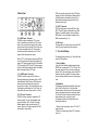
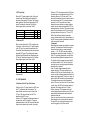
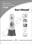
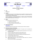
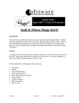
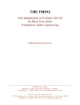
WIF2 – word clock interface
WIF2
word clock
interface
user manual
14
Hardware Synchroniser
for Digital Audio Workstations
TABLE OF CONTENTS
1. Front Panel
2. Back Panel
3. Time Code Display
I. Time Code Mode
II. Status Mode
AAAA Pull-Up/Pull-Down Factor
BBB Frame Rate Format
1. No Input
2. Video Input Only
3. LTC Input Only
4. VITC Input Only
5. Video & LTC
4. Unit Operation
I. Selection of Clock & Time Code
Source
II. Varispeed
5. Internal DIP Switches
I. Midi Cue Mode
II. Jam Duration
III. Default Standard
6. Specifications
-1-
2
4
5
5
5
6
7
7
7
8
8
8
9
10
10
11
11
12
1. Front Panel
(6) „lock“ Indicator
Indicates when the clock output is locked to an
incoming reference.
The incoming reference can be an LTC, VITC or
video signal.
(1) Time Code Display
The display has two modes: the Time Code Mode
and the Status Mode. In the Time Code Mode the
display shows decoded SMPTE time code applied to
LTC or VITC input. In the Status Mode the display
shows the Frame Rate Format on the left and the
Pull-Up/Pull-Down Factor on the right. The Frame
Rate Format relates to the frame rate of the incoming
time code or to the frame rate of the incoming video
signal. The Pull-Up/Pull-Down Factor shows the pullup/pull-down selected by the „Up/x1/Down“ Switch.
See the Time Code Display section (p. 5) for more
information.
(2) „on“ Switch
Turns the power to the WIF2 on and off.
Each time the MIF3 is powered up, it runs through
the display test, shows the software version and the
internal dip switch settings.
(3) „on“ indicator
Indicates proper function of the built-in power supply.
(4) „ltc“ Indicator
Indicates when a valid LTC signal is detected.
(5) „vitc“ Indicator
Indicates when a valid VITC signal is detected.
Note, when a video signal without VITC is applied,
the VITC indicator will not light.
-2-
(7) „up / x1 / down“ Switch
„up“ setting applies the Pull-Up Factor to the 44.1 or
48 kHz sample rate.
„x1“ setting leaves the clock at the exact rate of 44.1
or 48 kHz.
„down“ setting applies the Pull-Down Factor to the
44.1 or 48 kHz sample rate.
If you are not using any Pull-Up or Pull-Down sample
rates, set this switch to „x1“ which will let the WIF2
generate the standard 44.1 or 48 kHz sample rates.
Whenever this switch setting is changed, the Time
Code Display will switch to the Status Mode to
display the new Pull-Up/Pull-Down Factor.
Please see the Time Code Display sections (p. 5) for
further explanation of the pull-ups and pull-downs.
(8) „44.1 / 48“ kHz Switch
Switches the „x1/ x256“ output clock rate between
44.1 kHz and 48 kHz.
The exact sample rate also depends on the position
of the „up/x1/down“ switch located just to the left of
this switch. If you need to operate at exactly 44.1 kHz
or 48 kHz, please set the „up/x1/down“ switch to „x1“.
(9) „x1 / x256“ Switch
Changes the signal at the „Word output“ Connector
between Word Clock and Digidesign’s x256
Superclock. Set the switch to „x256“ when connecting
the WIF2 to Digidesign’s 888 or 882 interface. Set the
switch to „x1“ when connecting the WIF2 to any word
clock digital audio device.
-3-
MTC and a low jitter clock output. If the LTC format
changes, the Time Code Display will briefly switch to
the Status Mode to indicate the new format. For a
more detailed description please refer to the Unit
Operation section (p. 8):
2. Back Panel
(10) „VIDEO input“ Connector
This BNC connector accepts any VITC or video
signal. A possible source could be a VITC, a black
burst or any composite video signal. Even unstable
video sources such as consumer VCRs can be used.
The input is terminated with a 75 Ohm resistor. In
order to avoid double termination do not T-off the
signal to other terminated video inputs.
When a VITC or video signal is applied, the WIF2 will
lock to it and produce a low-jitter clock. Additionally,
when a VITC signal is applied, the WIF2 will translate
VITC time code into MTC. If the VITC format changes
the Time Code Display will briefly switch to the Status
Mode to indicate the new VITC format.
(11) „WORD output“ Connector
This BNC connector outputs a Word Clock or a
Superclock depending on the setting of the „x1/256“
switch.Neither the Word Clock or x256 Superclock
should ever be daisy chained. One output can
properly drive one input. The cable length for a word
clock signal should be limited to 4,5 m (15 feet), for
the Superclock it has to be kept under 1 m (3 feet).
(12) „LTC input“ Connector
This RCA connector accepts an unbalanced LTC
time code signal. The input circuit exhibits a wide
range of sensitivity: -40 to +20 dBu. This allows
reliable operation of the unit with nearly all LTC
sources. When an LTC signal is applied, the WIF2
will translate it to high-quality
-4-
(13) „MTC“ Connector
This 5-pin DIN connector outputs Midi Time Code
(MTC). The MTC signal can be applied to any MIDI
interface. For reliable operation use only shielded
MIDI cables. For more information, please see the
MIDI cue mode section (p. 10).
(14) VAC input
Use the provided AC power cord to connect the WIF2
to the AC power supply through this connector.
3. Time Code Display
The display has two modes: the (I.) Time Code Mode
and the (II.) Status Mode.
I. Time Code Mode
In the Time Code Mode the display shows decoded
SMPTE time code applied to LTC or VITC input. The
time code appears as hours, minutes, seconds and
frames. This is the normal display mode of the WIF2
whenever time code is applied. This mode provides
the user with the ability to monitor the incoming time
code.
II. Status Mode
This display mode indicates Frame Rate Format and
the Pull-Up/Pull-Down Factor. The Frame Rate
Format relates to the frame rate of the incoming time
code, or the frame rate of the incoming video signal.
The Pull-Up/Pull-Down Factor shows the pull-up/pulldown selected by the „up/x1/down“ switch.
The display will remain in the Status Mode in the
following two instances:
1. When the unit is powered up and no LTC or VITC
signal is present.
2. When only a video signal without VITC is applied
to the unit.
-5-
Otherwise, there are two other instances in which the
display briefly switches to the Status Mode before
reverting to the Time Code Mode:
1. Whenever the format of the LTC or VITC input
changes.
2. Whenever the „up/x1/down“ switch is toggled.
In fact, toggling the“up/x1/down“ switch is the easiest
way to redisplay the Status Mode information.
In the Status Mode, the 4 rightmost digits of the
display always indicate the Pull-Up/Pull-Down Factor.
The 3 left digits show the Frame Rate Format which
carries various meaning depending on the signals
applied to the WIF2.
BBB
AAAA
AAAA Pull-Up / Pull-Down Factor
In the Status Mode, the 4 rightmost digits of the
display show the Pull-Up/Pull-Down Factor engaged
by the „up/x1/down“ switch. This factor is applied to
either 44.1 kHz or 48 kHz base sample rate. The
following table helps you interpret the numbers.
Pull-Up/PullDown Factor
1.000
1.041
0.960
1.001
0.999
Description
No pull-up or pull-down.
Sample Rate will be exactly 44.1 or 48 kHz.
PAL pull-up
(25/24 or 4% change in the Sample Rate)
PAL pull-down
(24/25 or 4% change in the Sample Rate)
NTSC pull-up
(1001/1000 or 0.1% change in the Sample Rate)
NTSC pull-down
(1000/1001 or 0.1% change in the Sample Rate)
Remember the Pull-Up/Pull-Down Factor works in
conjunction with the „44.1/48“ switch to determine the
exact sample rate of the clock outputs.
-6-
BBB Frame Rate Format
1. No input
When the unit is powered up and no signal is applied
to either LTC or VITC connector, i.e. WIF2 is not
locking to any reference, the Frame Rate Format
follows to the default standard which can be defined
by the internal DIP switch 8. The table shows the
Pull-Up/Down Factors applied by the „up/x1/down“
Switch.
Frame Rate Format
Default Standard
Up
Down
25
30
25 fps
30 fps
1.041
1.001
0.960
0.999.
2. Video Input Only
When a video signal without VITC is applied to the
„Video input“ connector, the Frame Rate Format
indicates the frame rate of the applied video signal.
The following table relates the Frame Rate Format
with the video standard. The table shows the PullUp/Down Factors applied by the „up/x1/down“
Switch.
Frame Rate Format
Video Standard
Up
Down
25
29.
PAL / SECAM
NTSC
1.041
1.001
0.960
0.999.
3. LTC Input Only
When an LTC signal is applied to the „LTC input“
connector, the Frame Rate Format indicates the time
code format of the applied LTC signal. The following
provides a summary. The table shows the PullUp/Down Factors applied by the „up/x1/down“
Switch.
Frame Rate Format
Time Code Format
Up
Down
24
25
29d
30
30
24 fps
25 fps
29.97 fps drop frame
29.97 fps non drop frame**
30 fps
1.041
1.041
1.001
1.001
1.001
0.960
0.960
0.999.
0.999.
0.999.
** Note, the WIF2 detects 29.97 non drop frame
format as 30 fps when 29.97 fps LTC is applied
without any video signal. This will cause a pull down
by 0.1%. This Pull-down can be corrected by setting
the „Up/x1/Down“ Switch to the Up position. This
problem only occurs with 29.97 non drop format.
-7-
4. VITC Input Only
If there is only an LTC signal present, the WIF2 uses
the LTC as positional and clock reference. This
means that the word clock output is locked to the
LTC input. The time code data from the LTC is
translated to the MTC output.
If there is a LTC signal and a video signal present at
the same time, the WIF2 uses the LTC signal as
positional reference for the MTC output and the video
signal as clock reference for the word clock output.
If there is a VITC video signal present, the WIF2 uses
this video signal as clock reference and the VITC as
positional reference. If VITC-video and LTC are
present at the same time, the video signal is used as
clock reference and the LTC is used as positional
reference. If the LTC signal falls out of range
because the source machine is stopped, jogged or
shuttled, the unit switches automatically to VITC for
positional reference. Once the LTC is restored to play
speed, the unit switches back to LTC as the source
time code reference. At all points „LTC“ and „VITC“
LEDs of the front panel indicate the time code
source. Automatic switch-over is a special feature of
the WIF2 because it always guarantees the selection
of the best possible time code.
II. Varispeed
Many digital audio systems are capable of varispeed
operation. The equipment will follow the change in
the master clock speed up to some percentage,
typically +-10%. The WIF2 supports varispeed
operation when deriving the master clock from LTC.
If the LTC is gradually changed the clock will follow
the change to keep digital audio equipment in sync.
The deviation from the nominal play speed that will
be tracked is limited to 10%. This is to prevent the
errors that occur in many digital audio workstations
when this limit is breached.
If the LTC speed changes dramatically, which
happens when the LTC source machine stops or
shuttles, the WIF2 will not follow the change. In this
case the unit will continue generating the clock at the
sample rate just before the LTC went out of range. In
other words the WIF2 exhibits „sample rate memory“.
This sample rate memory serves to dramatically
reduce LTC lock up time. Once the LTC returns back
to useful range, the WIF2 will relock and gradually
adjust the clock to match the new LTC speed.
Similary, whenever LTC disappears the unit will
continue generating clock without any glich. The unit
remembers the last sample rate and continues to
freewheel at that rate.
Note: you may not want the clocks to continue at the
off-speed rate due to a previous off-pich operation.
To reset WIF2 clock to nominal frequency turn the
unit off or toggle the „Up/x1/Down“ switch.
-8-
-9-
When an VITC signal is applied to the „Video input“
connector, the Frame Rate Format indicates the
frame rate of the applied VITC signal. The following
tablel relates the Frame Rate Format with the VITC
format. The table also shows the Pull-Up/Down
Factors applied by the „up/x1/down“ Switch.
Frame Rate Format
VITC Format
Up
Down
25
29d
29.
PAL
NTSC drop frame
NTSC non drop frame
1.041
1.001
1.001
0.960
0.999.
0.999.
5. Video and LTC
When an video signal without VITC is applied to the
„Video input“ connector and an LTC signal is applied
to the „LTC input“ connector at the same time, the
Frame Rate Format indicates the time code format of
the applied LTC signal. The following table relates
the Frame Rate Format with video standard and the
LTC format. The table also shows the Pull-Up/Down
Factors applied by the „up/x1/down“ Switch.
Frame Rate
Format
Video
Standard
LTC Format
Up
Down
25
29d
29.
PAL
NTSC
NTSC
25 fps
29.97 fps drop
29.97 fps non drop
1.041
1.001
1.001
0.960
0.999.
0.999.
Note, the LTC format must mach the corrosponding
video standard!
4. Unit Operation
I. Selection of Clock & Time Code Source
5. Internal DIP Switches
The WIF2 unit has eight internal DIP switches to
preset the synchronizer. To get the information how
these eight internal swiches are set, it is not
necessary to open the box, because in the power up
routine the display shows the current settings as
abbreviations.The routine starts with the display test
8.8.8.8.8.8.8.8.
and shows the firmware version briefly
SoFt
2.10
followed by the midi cue mode (dip 1-3) and the jam
duration (dip 7)
FuLL
J8
and remains in the status mode as long as no LTC or
VITC signals are applied.
25
1.0 00
The table below lists the functions of the DIP
switches and the according display abbreviations:
DIP-No.
1-2-3
Settings
Abbreviation.
0-0-0
1-0-0
0-1-0
0-0-1
1-0-1
oFF
FuLL
Loc
qFb
qFb-2
0
1
0
1
J8
J32
25
30
7
8
Function
midi cue mode
no output during jog/shuttle
MTC Full Message
MMC locate command
quarter frame bursts
quarter frame bursts-2
Jam Durationtion
8 frames
32 frames
default standard 25 fps
default standard 30 fps
Unfortunately many devices which are using MTC do
not have implemented the Full message.
For that reason the WIF2 supports some other midi
cue modes for locating or cueing your sequencer /
audio workstation frame accurately to a master time
code. One of these methods to cue up a DAW is the
use of the MMC „Locate“ command, if the slaved
DAW supports MMC slave mode together with MTC
slave mode. Therefore set the midi cue mode to
Locate. (for example with Digidesign ProTools 4.2,
Roland VS-880, Fostex FD8...) Then the WIF2
outputs an MMC locate command instead of the Full
message.
Other recording software can be located by a burst of
several quarter frames. The Creamware Triple DAT
Software, for example, works fine with the midi cue
mode qFb-2.
II. DIP 7, Jam Duration
The time code drop out correction bridges up to 8
frames. DIP switch 7 sets the error correction to 32
frames. This causes also a post-roll time of 32
frames after the master time code has stopped.
III. DIP 8, Default Standard
The default standard setting defines the time code
standard when the unit is powered up.
I. DIP 1-3, Midi Cue Mode
Midi Time Code is the standard used to translate
SMPTE time code into MIDI messages. There are
two basic types of messages, described as Quarter
Frame and Full message. The Quarter Frame
message is used for normal running status at play
speed. The Full message communicates a specific
time for locating or cueing.
- 10 -
- 11 -
6. Specifications
LTC input
RCA female, -40 to 20 dBu, 10k ohms
0,5 to 200% of playspeed, reverse and positional,
format auto-detection (24, 25, 30 drop, 30 fps)
Video input
BNC female, 75 ohms terminated
PAL/NTSC Composite Sync
reads VITC in lines 6 to 22
MIDI output
5-pin DIN, The Complete MIDI 1.0
MTC quarter frame and full messages
MTC quarter bursts, MMC locate
Word output
BNC female, 75 ohms, TTL
x1 or x256 sample rate,
42.336, 44.056, 44.100, 44.144, 45.937 kHz
46.080, 47.952, 48.000, 48.048, 50.000 kHz
Lock range +/- 10% of nominal speed
Clock jitter < 1 ns per audio frame
Resolution 23 ppm
Power
Euro EN 60.320, 230 VAC, 50 Hz, 30 mA,
(115 VAC, 60 Hz, 60 mA version also available)
LED Display
8 x HP 7503, 6mm (0,3“) red
Dimensions
11,4 cm W x 3,1 cm H x 16,8 cm D,
1U-19“ rackmount kit available
Weight
0,7 kg
- 12 -