1
SAFETY PRECAUTIONS
(Read these precautions before using this product.)
Before using this product, please read this manual and the relevant manuals carefully and pay full attention
to safety to handle the product correctly.
In this manual, the safety precautions are classified into two levels: "
WARNING" and "
CAUTION".
WARNING
Indicates that incorrect handling may cause hazardous conditions,
resulting in death or severe injury.
CAUTION
Indicates that incorrect handling may cause hazardous conditions,
resulting in minor or moderate injury or property damage.
Under some circumstances, failure to observe the precautions given under "
CAUTION" may lead to
serious consequences.
Observe the precautions of both levels because they are important for personal and system safety.
Make sure that the end users read this manual and then keep the manual in a safe place for future
reference.
[Design Precautions]
WARNING
● Configure safety circuits external to the programmable controller to ensure that the entire system
operates safely even when a fault occurs in the external power supply or the programmable controller.
Failure to do so may result in an accident due to an incorrect output or malfunction.
(1) Emergency stop circuits, protection circuits, and protective interlock circuits for conflicting
operations (such as forward/reverse rotations or upper/lower limit positioning) must be configured
external to the programmable controller.
(2) When the programmable controller detects an abnormal condition, it stops the operation and all
outputs are:
• Turned off if the overcurrent or overvoltage protection of the power supply module is activated.
• Held or turned off according to the parameter setting if the self-diagnostic function of the head
module detects an error such as a watchdog timer error.
All outputs may turn on when an error occurs in the part, such as I/O control part, where the head
module cannot detect any error. To ensure safety operation in such a case, provide a safety
mechanism or a fail-safe circuit external to the programmable controller.
For the fail-safe circuit, refer to Page 146, Appendix 10.
(3) Outputs may remain on or off due to a failure of a component such as a relay and transistor in an
output circuit. Configure an external circuit for monitoring output signals that could cause a
serious accident.
1
[Design Precautions]
WARNING
● In an output circuit, when a load current exceeding the rated current or an overcurrent caused by a
load short-circuit flows for a long time, it may cause smoke and fire. To prevent this, configure an
external safety circuit, such as a fuse.
● Configure a circuit so that the programmable controller is turned on first and then the external power
supply. If the external power supply is turned on first, an accident may occur due to an incorrect output
or malfunction.
● Configure a circuit so that the programmable controller is turned off first and then the external power
supply. If the external power supply is turned off first, an accident may occur due to an incorrect output
or malfunction.
● For the operating status of each station after a communication failure, refer to relevant manuals for
each network. Incorrect output or malfunction due to a communication failure may result in an
accident.
● When changing data from a peripheral device connected to the head module during operation,
configure an interlock circuit in the program of the master station to ensure that the entire system will
always operate safely.
For other controls to a running programmable controller (such as modification of the master station
program or operating status change), read relevant manuals carefully and ensure the safety before
the operation. Especially, in the case of a control from an external device to a remote programmable
controller, immediate action cannot be taken for a problem on the programmable controller due to a
communication failure. To prevent this, configure an interlock circuit in the program of the master
station, and determine corrective actions to be taken between the external device and head module in
case of a communication failure.
● When a module is faulty, an analog output may remain on. Configure an external interlock circuit for
output signals that could cause a serious accident.
● Do not write any data to the "system area" and "write-protect area" (R) of the buffer memory in the
intelligent function module. Also, do not use any "use prohibited" signals as an output signal from the
head module to the intelligent function module. Doing so may cause malfunction of the programmable
controller system.
● Disconnection of any communication cable (such as a CC-Link dedicated cable) may cause an
unstable line condition, resulting in a communication failure at multiple stations on the network.
Configure an interlock circuit in the program to ensure that the entire system will always operate
safety even in case of a communication failure. Failure to do so may result in an accident due to an
incorrect output or malfunction.
2
[Design Precautions]
CAUTION
● Do not install the control lines or communication cables together with the main circuit lines or power
cables. Keep a distance of 100mm or more between them. Failure to do so may result in malfunction
due to noise.
● During control of an inductive load such as a lamp, heater, or solenoid valve, a large current
(approximately ten times greater than normal) may flow when the output is turned from off to on.
Therefore, use a module that has a sufficient current rating.
● When the system is powered on, a surge voltage may occur or inrush current may flow between
output terminals of an analog output module. Start the control after analog outputs are stabilized.
[Installation Precautions]
WARNING
● Shut off the external power supply (all phases) used in the system before mounting or removing a
module. Failure to do so may result in electric shock or cause the module to fail or malfunction.
[Installation Precautions]
CAUTION
● Use the head module in an environment that meets the general specifications in this manual. Failure
to do so may result in electric shock, fire, malfunction, or damage to or deterioration of the product.
● To interconnect modules, engage the respective connectors and securely lock the module joint levers
until they click. Incorrect interconnection may cause malfunction, failure, or drop of the module.
● Tighten the screw within the specified torque range. Undertightening can cause drop of the screw,
short circuit or malfunction. Overtightening can damage the screw and/or module, resulting in drop,
short circuit, or malfunction.
● Do not directly touch any conductive parts and electronic components of the module. Doing so can
cause malfunction or failure of the module.
[Wiring Precautions]
WARNING
● Shut off the external power supply (all phases) used in the system before wiring. Failure to do so may
result in electric shock or cause the module to fail or malfunction.
● After installation and wiring, attach the included terminal cover to the module before turning it on for
operation. Failure to do so may result in electric shock.
3
[Wiring Precautions]
CAUTION
● Individually ground the FG and LG terminals of the programmable controller with a ground resistance
of 100or less. Failure to do so may result in electric shock or malfunction.
● Use applicable solderless terminals and tighten them within the specified torque range. If any spade
solderless terminal is used, it may be disconnected when a terminal block screw comes loose,
resulting in failure.
● Check the rated voltage and terminal layout before wiring to the module, and connect the cables
correctly. Connecting a power supply with a different voltage rating or incorrect wiring may cause a fire
or failure.
● Connectors for external devices must be crimped or pressed with the tool specified by the
manufacturer, or must be correctly soldered. Incomplete connections may cause short circuit, fire, or
malfunction.
● Securely connect the connector to the module.
● Do not install the control lines or communication cables together with the main circuit lines or power
cables. Keep a distance of 100mm or more between them. Failure to do so may result in malfunction
due to noise.
● Place the cables in a duct or clamp them. If not, dangling cable may swing or inadvertently be pulled,
resulting in damage to the module or cables or malfunction due to poor contact.
4
[Wiring Precautions]
CAUTION
● Check the interface type and properly connect the cable. Incorrect wiring (connecting the cable to an
incorrect interface) may cause failure of the module and external device.
● Tighten the terminal block screw within the specified torque range. Undertightening can cause short
circuit, fire, or malfunction. Overtightening can damage the screw and/or module, resulting in drop,
short circuit, fire, or malfunction.
● When disconnecting the cable from the module, do not pull the cable by the cable part. For the cable
with connector, hold the connector part of the cable. For the cable connected to the terminal block,
loosen the terminal screw. Pulling the cable connected to the module may result in malfunction or
damage to the module or cable.
● Prevent foreign matter such as dust or wire chips from entering the module. Such foreign matter can
cause a fire, failure, or malfunction.
● A protective film is attached to the top of the module to prevent foreign matter, such as wire chips,
from entering the module during wiring. Do not remove the film during wiring. Remove it for heat
dissipation before system operation.
● When connecting a CC-Link system master/local module to the head module, use CC-Link dedicated
cables for the CC-Link system. If any other cable is used, the performance of the CC-Link system is
not guaranteed. Observe the cable specifications (maximum cable length and station-to-station cable
length) described in the MELSEC-L CC-Link System Master/Local Module User's Manual. If not,
proper data transmission is not guaranteed.
● When the high-speed counter module is connected to the head module, ground the shield cable on
the encoder side (relay box). Always ground the FG and LG terminals to the protective ground
conductor. Failure to do so may cause malfunction.
● Mitsubishi programmable controllers must be installed in control panels. Connect the main power
supply to the power supply module in the control panel through a relay terminal block. Wiring and
replacement of a power supply module must be performed by qualified maintenance personnel with
knowledge of protection against electric shock. For wiring methods, refer to the MELSEC-L CPU
Module User's Manual (Hardware Design, Maintenance and Inspection).
[Startup and Maintenance Precautions]
WARNING
● Do not touch any terminal while power is on. Doing so will cause electric shock or malfunction.
● Shut off the external power supply (all phases) used in the system before cleaning the module or
retightening the terminal block screws or connector screws. Failure to do so may result in electric
shock.
5
[Startup and Maintenance Precautions]
CAUTION
● Before performing online operations (especially, master station program modification, forced output,
and operating status change) for the running head module from the peripheral device connected, read
relevant manuals carefully and ensure the safety. Improper operation may damage machines or
cause accidents.
● Do not disassemble or modify the module. Doing so may cause failure, malfunction, injury, or a fire.
● Use any radio communication device such as a cellular phone or PHS (Personal Handy-phone
System) more than 25cm away in all directions from the programmable controller. Failure to do so
may cause malfunction.
● Shut off the external power supply (all phases) used in the system before mounting or removing a
module. Failure to do so may cause the module to fail or malfunction.
● Tighten the terminal block screws or connector screws within the specified torque range.
Overtightening can damage the screw and/or module, resulting in drop, short circuit, or malfunction.
● After the first use of the product (module and terminal block), the number of
connections/disconnections is limited to 50 times (in accordance with IEC 61131-2). Exceeding the
limit may cause malfunction.
● Before handling the module, touch a conducting object such as a grounded metal to discharge the
static electricity from the human body. Failure to do so may cause the module to fail or malfunction.
[Operating Precautions]
CAUTION
● When changing data and operating status, or modifying program of a running programmable
controller from an external device such as a personal computer connected to an intelligent function
module, read relevant manuals carefully and ensure the safety before operation. Incorrect change or
modification may cause system malfunction, damage to the machines, or accidents.
● Do not power off the programmable controller or reset the head module while setting values of a
module connected to the head module are written from the buffer memory to the flash ROM. Doing do
so will make the data in the flash ROM unreliable, and the data need to be set in the buffer memory
and written to the flash ROM again. Also, it may cause the module to fail or malfunction.
[Disposal Precautions]
CAUTION
● When disposing of this product, treat it as industrial waste.
6
CONDITIONS OF USE FOR THE PRODUCT
(1) Mitsubishi programmable controller ("the PRODUCT") shall be used in conditions;
i) where any problem, fault or failure occurring in the PRODUCT, if any, shall not lead to any major
or serious accident; and
ii) where the backup and fail-safe function are systematically or automatically provided outside of
the PRODUCT for the case of any problem, fault or failure occurring in the PRODUCT.
(2) The PRODUCT has been designed and manufactured for the purpose of being used in general
industries.
MITSUBISHI SHALL HAVE NO RESPONSIBILITY OR LIABILITY (INCLUDING, BUT NOT
LIMITED TO ANY AND ALL RESPONSIBILITY OR LIABILITY BASED ON CONTRACT,
WARRANTY, TORT, PRODUCT LIABILITY) FOR ANY INJURY OR DEATH TO PERSONS OR
LOSS OR DAMAGE TO PROPERTY CAUSED BY the PRODUCT THAT ARE OPERATED OR
USED IN APPLICATION NOT INTENDED OR EXCLUDED BY INSTRUCTIONS, PRECAUTIONS,
OR WARNING CONTAINED IN MITSUBISHI'S USER, INSTRUCTION AND/OR SAFETY
MANUALS, TECHNICAL BULLETINS AND GUIDELINES FOR the PRODUCT.
("Prohibited Application")
Prohibited Applications include, but not limited to, the use of the PRODUCT in;
• Nuclear Power Plants and any other power plants operated by Power companies, and/or any
other cases in which the public could be affected if any problem or fault occurs in the PRODUCT.
• Railway companies or Public service purposes, and/or any other cases in which establishment of
a special quality assurance system is required by the Purchaser or End User.
• Aircraft or Aerospace, Medical applications, Train equipment, transport equipment such as
Elevator and Escalator, Incineration and Fuel devices, Vehicles, Manned transportation,
Equipment for Recreation and Amusement, and Safety devices, handling of Nuclear or
Hazardous Materials or Chemicals, Mining and Drilling, and/or other applications where there is a
significant risk of injury to the public or property.
Notwithstanding the above, restrictions Mitsubishi may in its sole discretion, authorize use of the
PRODUCT in one or more of the Prohibited Applications, provided that the usage of the PRODUCT
is limited only for the specific applications agreed to by Mitsubishi and provided further that no
special quality assurance or fail-safe, redundant or other safety features which exceed the general
specifications of the PRODUCTs are required. For details, please contact the Mitsubishi
representative in your region.
7
INTRODUCTION
Thank you for purchasing the Mitsubishi MELSEC-L series programmable controllers.
This manual describes the operating procedure, system configuration, parameter setting, functions, and
troubleshooting of the CC-Link IE Field Network head module (hereafter abbreviated as head module).
Before using this product, please read this manual and the relevant manuals carefully and develop familiarity with the
functions and performance of the MELSEC-L series programmable controller to handle the product correctly.
8
RELEVANT MANUALS
(1) CC-Link IE Field Network (relevant) manuals
When using the CC-Link IE Field Network for the first time, refer to the CC-Link IE Field Network Master/Local
Module User's Manual.
Manual name
<manual number (model code)>
Description
MELSEC-Q CC-Link IE Field Network Master/Local Module
Overview of the CC-Link IE Field Network, and specifications,
User's Manual
procedures before operation, system configuration, installation, wiring,
settings, functions, programming, and troubleshooting of the CC-Link
<SH-080917ENG, 13JZ47>
IE Field Network master/local module
MELSEC-L CC-Link IE Field Network Master/Local Module User's
Overview of the CC-Link IE Field Network, and specifications,
Manual
procedures before operation, system configuration, installation, wiring,
settings, functions, programming, and troubleshooting of the CC-Link
<SH-080972ENG, 13JZ54>
IE Field Network master/local module
CC-Link IE Field Network Interface Board User's Manual (For
Specifications, procedures before operation, system configuration,
SW1DNC-CCIEF-B)
settings, functions, programming, and troubleshooting of the CC-Link
<SH-080980ENG, 13JZ58>
IE Field Network interface board
(2) Operating manual
Manual name
<manual number (model code)>
GX Works2 Version1 Operating Manual (Common)
<SH-080779ENG, 13JU63>
Description
System configuration, parameter settings, and online operations
(common to Simple project and Structured project) of GX Works2
9
CONTENTS
CONTENTS
SAFETY PRECAUTIONS . . . . . . . . . . . . . . . . . . . . . . . . . . . . . . . . . . . . . . . . . . . . . . . . . . . . . . . . . . . . . 1
CONDITIONS OF USE FOR THE PRODUCT . . . . . . . . . . . . . . . . . . . . . . . . . . . . . . . . . . . . . . . . . . . . . 7
INTRODUCTION . . . . . . . . . . . . . . . . . . . . . . . . . . . . . . . . . . . . . . . . . . . . . . . . . . . . . . . . . . . . . . . . . . . . 8
RELEVANT MANUALS . . . . . . . . . . . . . . . . . . . . . . . . . . . . . . . . . . . . . . . . . . . . . . . . . . . . . . . . . . . . . . . 9
MANUAL PAGE ORGANIZATION . . . . . . . . . . . . . . . . . . . . . . . . . . . . . . . . . . . . . . . . . . . . . . . . . . . . . . 13
TERM. . . . . . . . . . . . . . . . . . . . . . . . . . . . . . . . . . . . . . . . . . . . . . . . . . . . . . . . . . . . . . . . . . . . . . . . . . . . 14
PACKING LIST . . . . . . . . . . . . . . . . . . . . . . . . . . . . . . . . . . . . . . . . . . . . . . . . . . . . . . . . . . . . . . . . . . . . 16
CHAPTER 1 HEAD MODULE
17
CHAPTER 2 PART NAMES
20
CHAPTER 3 SPECIFICATIONS
24
3.1
General Specifications . . . . . . . . . . . . . . . . . . . . . . . . . . . . . . . . . . . . . . . . . . . . . . . . . . . . . . . 24
3.2
Performance Specifications . . . . . . . . . . . . . . . . . . . . . . . . . . . . . . . . . . . . . . . . . . . . . . . . . . . 25
3.3
Function List . . . . . . . . . . . . . . . . . . . . . . . . . . . . . . . . . . . . . . . . . . . . . . . . . . . . . . . . . . . . . . . 27
CHAPTER 4 PROCEDURES BEFORE OPERATION
4.1
Initial Start-up Procedure . . . . . . . . . . . . . . . . . . . . . . . . . . . . . . . . . . . . . . . . . . . . . . . . . . . . . 28
4.2
Procedure for Changing the Head Module . . . . . . . . . . . . . . . . . . . . . . . . . . . . . . . . . . . . . . . . 30
CHAPTER 5 SYSTEM CONFIGURATION
33
5.1
Head Module System Configuration . . . . . . . . . . . . . . . . . . . . . . . . . . . . . . . . . . . . . . . . . . . . . 33
5.2
Applicable Systems . . . . . . . . . . . . . . . . . . . . . . . . . . . . . . . . . . . . . . . . . . . . . . . . . . . . . . . . . 34
CHAPTER 6 INSTALLATION AND WIRING
6.1
6.2
35
Wiring Environment and Installation Position . . . . . . . . . . . . . . . . . . . . . . . . . . . . . . . . . . . . . . 35
6.1.1
Installation environment . . . . . . . . . . . . . . . . . . . . . . . . . . . . . . . . . . . . . . . . . . . . . . . . . . . . . 35
6.1.2
Installation position. . . . . . . . . . . . . . . . . . . . . . . . . . . . . . . . . . . . . . . . . . . . . . . . . . . . . . . . . 35
Installation. . . . . . . . . . . . . . . . . . . . . . . . . . . . . . . . . . . . . . . . . . . . . . . . . . . . . . . . . . . . . . . . . 36
6.2.1
Connecting modules . . . . . . . . . . . . . . . . . . . . . . . . . . . . . . . . . . . . . . . . . . . . . . . . . . . . . . . 37
6.2.2
Mounting the modules on a DIN rail. . . . . . . . . . . . . . . . . . . . . . . . . . . . . . . . . . . . . . . . . . . . 38
6.2.3
Changing modules on a DIN rail . . . . . . . . . . . . . . . . . . . . . . . . . . . . . . . . . . . . . . . . . . . . . . 41
6.3
Wiring to the Power Supply Modules . . . . . . . . . . . . . . . . . . . . . . . . . . . . . . . . . . . . . . . . . . . . 43
6.4
Testing the Head Module Before Wiring . . . . . . . . . . . . . . . . . . . . . . . . . . . . . . . . . . . . . . . . . . 43
6.5
Wiring to the Head Module . . . . . . . . . . . . . . . . . . . . . . . . . . . . . . . . . . . . . . . . . . . . . . . . . . . . 45
6.5.1
Wiring . . . . . . . . . . . . . . . . . . . . . . . . . . . . . . . . . . . . . . . . . . . . . . . . . . . . . . . . . . . . . . . . . . . 45
6.5.2
Grounding . . . . . . . . . . . . . . . . . . . . . . . . . . . . . . . . . . . . . . . . . . . . . . . . . . . . . . . . . . . . . . . 47
6.5.3
Precautions . . . . . . . . . . . . . . . . . . . . . . . . . . . . . . . . . . . . . . . . . . . . . . . . . . . . . . . . . . . . . . 48
CHAPTER 7 PARAMETER SETTING
10
28
49
7.1
PLC Parameters . . . . . . . . . . . . . . . . . . . . . . . . . . . . . . . . . . . . . . . . . . . . . . . . . . . . . . . . . . . . 50
7.2
Network Parameters . . . . . . . . . . . . . . . . . . . . . . . . . . . . . . . . . . . . . . . . . . . . . . . . . . . . . . . . . 60
7.3
Remote Password . . . . . . . . . . . . . . . . . . . . . . . . . . . . . . . . . . . . . . . . . . . . . . . . . . . . . . . . . . 61
7.4
Intelligent Function Module Parameters . . . . . . . . . . . . . . . . . . . . . . . . . . . . . . . . . . . . . . . . . . 62
CHAPTER 8 CYCLIC TRANSMISSION
63
8.1
Cyclic Transmission of Bit Device Data . . . . . . . . . . . . . . . . . . . . . . . . . . . . . . . . . . . . . . . . . . 63
8.2
Cyclic Transmission of Word Device Data . . . . . . . . . . . . . . . . . . . . . . . . . . . . . . . . . . . . . . . . 69
CHAPTER 9 CC-LINK IE FIELD NETWORK DIAGNOSTICS
73
9.1
Diagnostic Items . . . . . . . . . . . . . . . . . . . . . . . . . . . . . . . . . . . . . . . . . . . . . . . . . . . . . . . . . . . . 73
9.2
Starting Diagnostics . . . . . . . . . . . . . . . . . . . . . . . . . . . . . . . . . . . . . . . . . . . . . . . . . . . . . . . . . 74
9.3
Diagnostic Screen. . . . . . . . . . . . . . . . . . . . . . . . . . . . . . . . . . . . . . . . . . . . . . . . . . . . . . . . . . . 76
9.4
Communication Test . . . . . . . . . . . . . . . . . . . . . . . . . . . . . . . . . . . . . . . . . . . . . . . . . . . . . . . . . 78
9.5
Cable Test. . . . . . . . . . . . . . . . . . . . . . . . . . . . . . . . . . . . . . . . . . . . . . . . . . . . . . . . . . . . . . . . . 78
9.6
System Monitor. . . . . . . . . . . . . . . . . . . . . . . . . . . . . . . . . . . . . . . . . . . . . . . . . . . . . . . . . . . . . 79
9.7
Remote Operation . . . . . . . . . . . . . . . . . . . . . . . . . . . . . . . . . . . . . . . . . . . . . . . . . . . . . . . . . . 79
CHAPTER 10 MAINTENANCE AND INSPECTION
80
10.1
Daily Inspection . . . . . . . . . . . . . . . . . . . . . . . . . . . . . . . . . . . . . . . . . . . . . . . . . . . . . . . . . . . . 80
10.2
Periodic Inspection . . . . . . . . . . . . . . . . . . . . . . . . . . . . . . . . . . . . . . . . . . . . . . . . . . . . . . . . . . 81
CHAPTER 11 TROUBLESHOOTING
82
11.1
Before Troubleshooting . . . . . . . . . . . . . . . . . . . . . . . . . . . . . . . . . . . . . . . . . . . . . . . . . . . . . . 82
11.2
Troubleshooting Procedure . . . . . . . . . . . . . . . . . . . . . . . . . . . . . . . . . . . . . . . . . . . . . . . . . . . 82
11.3
System Error History. . . . . . . . . . . . . . . . . . . . . . . . . . . . . . . . . . . . . . . . . . . . . . . . . . . . . . . . . 87
11.4
Checking the LEDs . . . . . . . . . . . . . . . . . . . . . . . . . . . . . . . . . . . . . . . . . . . . . . . . . . . . . . . . . . 89
11.5
11.6
Troubleshooting by Symptom . . . . . . . . . . . . . . . . . . . . . . . . . . . . . . . . . . . . . . . . . . . . . . . . . . 92
11.5.1
Cyclic transmission cannot be performed. . . . . . . . . . . . . . . . . . . . . . . . . . . . . . . . . . . . . . . . 92
11.5.2
Transient transmission cannot be performed. . . . . . . . . . . . . . . . . . . . . . . . . . . . . . . . . . . . . 92
Error Code List . . . . . . . . . . . . . . . . . . . . . . . . . . . . . . . . . . . . . . . . . . . . . . . . . . . . . . . . . . . . . 93
APPENDICES
107
Appendix 1 External Input/Output Forced On/Off . . . . . . . . . . . . . . . . . . . . . . . . . . . . . . . . . . . . . . 107
Appendix 2 File Password 32 . . . . . . . . . . . . . . . . . . . . . . . . . . . . . . . . . . . . . . . . . . . . . . . . . . . . . 110
Appendix 2.1
Setting file passwords. . . . . . . . . . . . . . . . . . . . . . . . . . . . . . . . . . . . . . . 111
Appendix 2.2
Password authentication . . . . . . . . . . . . . . . . . . . . . . . . . . . . . . . . . . . . . 115
Appendix 3 END Cover . . . . . . . . . . . . . . . . . . . . . . . . . . . . . . . . . . . . . . . . . . . . . . . . . . . . . . . . . . 117
Appendix 4 Link Special Relay (SB) List . . . . . . . . . . . . . . . . . . . . . . . . . . . . . . . . . . . . . . . . . . . . . 118
Appendix 5 Link Special Register (SW) List . . . . . . . . . . . . . . . . . . . . . . . . . . . . . . . . . . . . . . . . . . 119
Appendix 6 Special Relay (SM) List . . . . . . . . . . . . . . . . . . . . . . . . . . . . . . . . . . . . . . . . . . . . . . . . 122
Appendix 7 Special Register (SD) List . . . . . . . . . . . . . . . . . . . . . . . . . . . . . . . . . . . . . . . . . . . . . . 125
Appendix 8 Access and Attribute Codes. . . . . . . . . . . . . . . . . . . . . . . . . . . . . . . . . . . . . . . . . . . . . 133
Appendix 9 EMC and Low Voltage Directives. . . . . . . . . . . . . . . . . . . . . . . . . . . . . . . . . . . . . . . . . 134
Appendix 9.1
Requirements for Compliance with the EMC Directive . . . . . . . . . . . . . . . . . 134
Appendix 9.2
Requirements to Compliance with the Low Voltage Directive . . . . . . . . . . . . . 144
11
Appendix 10 General Safety Requirements . . . . . . . . . . . . . . . . . . . . . . . . . . . . . . . . . . . . . . . . . . . 146
Appendix 11 Calculating Heating Value of Programmable Controller. . . . . . . . . . . . . . . . . . . . . . . . 147
Appendix 11.1
Calculating the average power consumption . . . . . . . . . . . . . . . . . . . . . . . . 147
Appendix 12 Processing Time . . . . . . . . . . . . . . . . . . . . . . . . . . . . . . . . . . . . . . . . . . . . . . . . . . . . . 149
Appendix 13 New Function and Improved Function . . . . . . . . . . . . . . . . . . . . . . . . . . . . . . . . . . . . . 150
Appendix 14 Checking Serial Number and Function Version . . . . . . . . . . . . . . . . . . . . . . . . . . . . . . 150
Appendix 15 External Dimensions . . . . . . . . . . . . . . . . . . . . . . . . . . . . . . . . . . . . . . . . . . . . . . . . . . 153
INDEX
154
REVISIONS . . . . . . . . . . . . . . . . . . . . . . . . . . . . . . . . . . . . . . . . . . . . . . . . . . . . . . . . . . . . . . . . . . . . . . 156
WARRANTY . . . . . . . . . . . . . . . . . . . . . . . . . . . . . . . . . . . . . . . . . . . . . . . . . . . . . . . . . . . . . . . . . . . . . 157
12
MANUAL PAGE ORGANIZATION
In this manual, pages are organized and the symbols are used as shown below.
The following page illustration is for explanation purpose only, and is different from the actual pages.
"" is used for
screen names and items.
The chapter of
the current page is shown.
shows operating
procedures.
shows mouse
operations.*1
[ ] is used for items
in the menu bar and
the project window.
The section of
the current page is shown.
Ex. shows setting or
operating examples.
shows reference
manuals.
shows notes that
requires attention.
shows
reference pages.
shows useful
information.
*1
The mouse operation example is provided below.
Menu bar
Ex.
[Online]
[Write to PLC...]
Select [Online] on the menu bar,
and then select [Write to PLC...].
A window selected in the view selection area is displayed.
Ex.
[Parameter]
Project window
[PLC Parameter]
Select [Project] from the view selection
area to open the Project window.
In the Project window, expand [Parameter] and
select [PLC Parameter].
View selection area
13
TERM
Unless otherwise specified, this manual uses the following terms.
Term
GX Works2
Description
The product name of the software package for the MELSEC programmable controllers
Programming tool
Another term for GX Works2
CC-Link IE Field Network
An open field network that offers a high-speed and large-capacity data communication using Ethernet
(1000BASE-T).
CC-Link
A field network system where data processing for control and information can be simultaneously performed
at high speed.
Master/local module
A generic term for the QJ71GF11-T2 and LJ71GF11-T2 CC-Link IE Field Network master/local modules
Head module
Abbreviation for the LJ72GF15-T2 CC-Link IE Field Network head module
Network module
Generic term for the following modules:
• CC-Link IE Field Network module
• CC-Link IE Controller Network module
• Ethernet interface module
• MELSECNET/H module
• MELSECNET/10 module
Master station
A station that controls the entire network. This station can perform cyclic transmission and transient
transmission with all stations. Only one master station can be used in a network.
Local station
A station that performs cyclic transmission and transient transmission with the master station and other local
stations. The station is controlled by programs in the CPU module or other equivalent modules on the
station.
Remote I/O station
A station that exchanges I/O signals (bit data) with the master station by cyclic transmission.
Remote device station
A station that exchanges I/O signals (bit data) and I/O data (word data) with the master station by cyclic
transmission. This station responds to a transient transmission request from another station.
Intelligent device station
A station that exchanges I/O signals (bit data) and I/O data (word data) with the master station by cyclic
transmission. This station responds to a transient transmission request from another station and also issues
a transient transmission request to another station.
Slave station
Generic term for the stations other than the master station (local station, remote I/O station, remote device
station, and intelligent device station)
Reserved station
Station that is not actually connected, but must be included in the total number of the stations on the network
since it is to be connected in the future.
Relay station
Station that comprises of a programmable controller and multiple network modules and that relays data link
communication to another network.
Cyclic transmission
A communication function by which data are periodically exchanged among stations on the same network,
by using link devices (RX, RY, RWw, and RWr).
Transient transmission
A method for communication with another station, which is used when requested by a dedicated instruction
or GX Works2.
Data link
Generic term for cyclic transmission and transient transmission
Routing
A process of selecting paths for communication with other networks.
CC-Link IE Field Network requires communication paths to be preset using routing parameters to
communicate with stations on different networks.
For the head module, routing parameter setting is not required. Communications with other networks are
performed by routing parameters of the master station.
Dedicated instruction
Instruction that facilitates programming for the functions of the intelligent function modules
Link dedicated instruction
Dedicated instruction that is used for transient transmission with a programmable controller on another
station. This allows communications with not only the programmable controllers on the same network but
also those on the other networks. In addition to the CC-Link IE Field Network, the Ethernet, CC-Link IE
Controller Network, and MELSECNET/H are also accessible.
Reconnection
Operation that is performed to restart data link when a faulty station returns to normal.
Disconnection
Operation that is performed to stop data link when a data link error occurs.
Device
One of various devices (X, Y, W, etc.) inside the head module
Link device
Remote input (RX)
14
One of various devices (RX, RY, RWr, RWw, etc.) inside a module on the CC-Link IE Field Network
Bit data that is input from the slave station to the master station (with some exceptions for local stations)
User's manual for the master/local module used
Term
Remote output (RY)
Description
Bit data that is output from the master station to the slave station (with some exceptions for local stations)
User's manual for the master/local module used
Remote register (RWr)
16-bit data (word data) that is input from the slave station to the master station (with some exceptions for
local stations)
Remote register (RWw)
16-bit data (word data) that is output from the master station to the slave station (with some exceptions for
local stations)
User's manual for the master/local module used
User's manual for the master/local module used
Link special relay (SB)
Bit data that indicates the module operating status and data link status of the CC-Link IE Field Network
Link special register (SW)
16-bit data (word data) that indicates the module operating status and data link status of the CC-Link IE
Field Network
Parameter memory
A flash ROM that is built in the head module and used for storing parameters of the head module.
Intelligent function module
A MELSEC-Q/L series module that has functions other than input and output, such as an A/D or D/A
converter module.
Buffer memory
The memory of an intelligent function module, which is used to store data (such as setting values and
monitored values) for communication with a CPU module.
RAS
Abbreviation for Reliability, Availability, and Serviceability. A generic term used to describe the easy use of
automated equipment.
RIRD
Abbreviation for JP.RIRD and GP.RIRD
Dedicated instruction to be used in a program of the master and local modules
RIWT
Abbreviation for JP.RIWT and GP.RIWT
Dedicated instruction to be used in a program of the master and local modules
15
PACKING LIST
The following items are included in the package of this product. Before use, check that all the items are included.
LJ72GF15-T2
Head module + END cover (L6EC)
16
Safety Guidelines (IB-0800455)
CHAPTER 1 HEAD MODULE
CHAPTER 1
HEAD MODULE
1
The head module can connect MELSEC-L series I/O modules and intelligent function modules on CC-Link IE Field
Network.
The head module can be used as an intelligent device station on the CC-Link IE Field Network.
For CC-Link IE Field Network, refer to the following.
Relevant master/local module user's manual
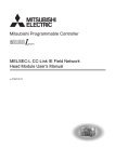
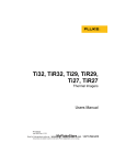
(1) Cyclic transmission
The I/O signals of the module connected to the head module can operate as those of the master station.
(
Page 63, CHAPTER 8)
For example, when the output (Y) of the master station is turned on, the output (Y) of the module connected to
the head module turns on.
Master station
Head module
(Intelligent device station)
CPU module
Master
station
Head module
Input module
X
RX
RX
X
Y
RY
RY
RWw
RWw
RWr
RWr
W
Output
module
Intelligent
function module
X
Y
Y
Buffer
memory
Y
17
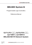
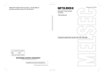
(2) Transient transmission
The master station and a local station can directly access head module devices and the buffer memory in an
intelligent function module by transient transmission. Communications with other stations on other networks can
also be made.
The master station and a local station send requests to the head module by dedicated instructions.
(
Relevant master/local module user's manual)
Master station
CPU module
Command
Head module
Intelligent
function module
REMFR
Device
Buffer memory
1234H
1234H
(3) Setting parameters
Parameters for the head module can be set using software, GX Works2. Creating parameter setting programs is
not necessary. (
18
Page 49, CHAPTER 7)
CHAPTER 1 HEAD MODULE
1
(4) Diagnostics
GX Works2 facilitates diagnosing the head module and connected modules. (
Page 73, CHAPTER 9,
Page 82, Section 11.2)
19
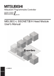
CHAPTER 2
PART NAMES
This chapter describes each part and name of the head module.
1)
6)
4)
2)
5)
7)
3)
6)
No.
Name
RUN LED
Description
Indicates the operating status.
On
Operating normally. (RUN status)
Working normally. (STOP status)
• The switch of the head module is set to STOP. (Transfer between the devices in the head module is
stopped.)
Flashing
• The master station is in the STOP status. (Transfer between the devices in the head module is
continued.)
• Accepting remote STOP request
• The head module has stopped due to an error (except a watchdog timer error).
Off
MODE LED
1)
On
Online mode
Flashing
Test mode
Off
Offline mode
REM. LED
Indicates the operating status of the own station.
On
Operating normally.
Flashing
Has not been reset after writing to PLC. Or, forced input/output registration is in progress.
Off
D LINK LED
The initial data are being processed, or an error has occurred in the own station.
Indicates the status of the data link.
On
Data link in operation (cyclic transmission in progress)
Flashing
Data link in operation (cyclic transmission stopped)
Off
Data link not in operation (disconnected) or the module is in offline mode.
SD LED
Indicates the send status of data.
On
Sending data.
Off
Data not sent.
RD LED
20
A hardware failure or a watchdog timer error has occurred.
Indicates the mode.
Indicates the reception status of data.
On
Receiving data.
Off
Data not received.
CHAPTER 2 PART NAMES
No.
Name
Description
Indicates the error status of the head module. The error details can be confirmed in CC-Link IE Field
ERR. LED
Network diagnostics. (
Page 73, CHAPTER 9)
On
An error has occurred in the head module.
Off
Working normally.
2
Indicates the received data status. When this LED is on, you can check the L ER LED for "P1" or "P2" to
see on which port the error was detected.
L ERR. LED
The error details can be confirmed in CC-Link IE Field Network diagnostics. (
Page 73, CHAPTER 9)
This LED automatically turns off when the module has received normal data or does not perform loopback
in ring topology.
• The module has received abnormal data.
On
• The module is performing loopback (only the head module whose serial number (first five digits) is
"12072" or later).
• The module has received normal data.
Off
1)
• The module does not perform loopback (only the head module whose serial number (first five digits) is
"12072" or later).
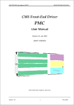
STATION NO.
Displays the station number of the head module.
Displays the station number.
Ex. Station No. 15
1
2
On
4
8
X100 X10 X1
10 + 5 = 15
Off
The station number has not been set.
PORT1 connector for CC-Link IE Field Network (RJ45 connector)
P1
Connect an Ethernet cable. (
Page 45, Section 6.5.1)
There is no restriction on the order of connecting the "P1" and "P2" connectors.
• The module has received abnormal data.
On
• The module is performing loopback (only the head module whose serial number (first five digits) is
"12072" or later).
L ER
LED
• The module has received normal data.
Off
2)
• The module does not perform loopback (only the head module whose serial number (first five digits) is
"12072" or later).
LINK
On
LED
Off
Linkup in progress.
Linkdown in progress.
PORT2 connector for CC-Link IE Field Network (RJ45 connector)
P2
Connect an Ethernet cable. (
Page 45, Section 6.5.1)
There is no restriction on the order of connecting the "P1" and "P2" connectors.
L ER LED
LINK LED
3)
Serial number display
(Same as the "P1" connector)
Displays the serial number printed on the rating plate.
21
No.
Name
Switch
Description
This switch controls the operation of the head module.
Resets the head module or switches it to test mode.
Operate the switch with your fingers. Use of a tool such as a screw driver may damage the switch.
• Reset method
1.
Hold the switch in the RESET/TEST
position for 1 second or more.
Switch
Do not release your hand from the switch
while it is in the RESET/TEST position.
: Flashing
Flashes several
times and then
turns off.
RESET/TEST
2.
times and then turns off.
3.
Switch
Check that the ERR. LED flashes several
Set the switch to the STOP position.
The switch automatically returns to the
STOP position when your hand is released.
4)
• Test method
For details on the test mode, refer to the explanation on the test mode.
(
Page 43, Section 6.4)
Stops the data transfer between the link devices of the head module (cyclic data from the master station)
and head module devices. (Stops the transfer while performing cyclic transmission with the master station,
and turns the output OFF.)
By stopping the data transfer, you can keep the input/output of the module attached to the head module
from getting sent to the master or local station. The STOP switch is used when performing a debug
operation between modules attached to the head module and external devices.
Ex. Debugging with an external device using the STOP switch
Set the switch to "STOP".
(2) Data transfer is stopped between the link devices of the head module and the head module devices,
and the devices are separated from the master station control.
(3) Perform an input/output test between the module connected to the head module and the external
device. Since the data transfer is stopped, the input/output status data are not sent to the master or
the local station.
(4) When the test is complete, write the parameter to the head module and start the system operation.
STOP*1
(1)
Starts the data transfer between the link devices of the head module (cyclic data from the master station)
and the head module devices.
RUN
The output from the master station is output from the module connected to the head module.
The input from the module attached to the head module is input to the master station.
5)
USB connector
A connector for connecting to GX Works2. (Connector type: miniB)
6)
Module joint levers
Levers for connecting modules each other.
7)
DIN rail hook
A hook used to mount the module to a DIN rail.
*1
22
Even if the switch is set to "STOP", the master station will indicate that a cyclic transmission is being performed in the
head module.
CHAPTER 2 PART NAMES
Remark
● Opening and closing the front cover of the head module
The cover on the front of the head module is equipped with a stopper. If you open the cover until it clicks, it will stay open.
Stopper
Pull the cover so that
the stopper will be set
easily.
Open the cover.
● LED indication during a line test
The following LEDs flash while a circuit test is performed from the master station.
• MODE LED
• D LINK LED
• × 100 LED
: On
: Flashing
Flashing
For information on how to perform a line test, refer to the following.
User's manual for the master/local module used
23
2
CHAPTER 3
SPECIFICATIONS
This chapter describes the specifications of the head module.
3.1
General Specifications
Item
Specifications
Operating ambient
0 to 55°C
temperature
Storage ambient
-25 to 75°C
temperature
Operating ambient
humidity
5 to 95%RH, non-condensing
Storage ambient
humidity
Frequency
Vibration resistance
Compliant with
Under
JIS B 3502 and
intermittent
IEC 61131-2
vibration
Constant
acceleration
Sweep count
10 times each in
5 to 8.4Hz
-
3.5mm
8.4 to 150Hz
9.8m/s2
-
Under continuous
5 to 8.4Hz
-
1.75mm
vibration
8.4 to 150Hz
4.9m/s2
-
Operating atmosphere
directions
-
No corrosive gases
Operating altitude*1
0 to 2000m
Installation location
Inside a control panel
II or less
category*2
Pollution degree*3
Equipment class
*1
*2
*3
2 or less
Class I
Do not use or store the programmable controller under pressure higher than the atmospheric pressure of altitude 0m.
Doing so may cause malfunction. When using the programmable controller under pressure, please consult your local
Mitsubishi representative.
This indicates the section of the power supply to which the equipment is assumed to be connected between the public
electrical power distribution network and the machinery within premises.
Category II applies to equipment for which electrical power is supplied from fixed facilities. The surge voltage withstand
level for up to the rated voltage of 300V is 2500V.
This index indicates the degree to which conductive material is generated in terms of the environment in which the
equipment is used.
Pollution level 2 is when only non-conductive pollution occurs. A temporary conductivity caused by condensing must be
expected occasionally.
To make the programmable controller comply with the EMC and Low Voltage Directives, refer to
10.
24
X, Y, and Z
Compliant with JIS B 3502 and IEC 61131-2 (147m/s2, 3 times each in X, Y, and Z directions)
Shock resistance
Overvoltage
Half amplitude
Page 146, Appendix
CHAPTER 3 SPECIFICATIONS
3.2
Performance Specifications
For the specifications of the entire CC-Link IE Field Network, refer to the user's manual for the master/local module
used.
Item
Specifications
CC-Link IE Field Network
3
RWw
1024 points, 2KB
Maximum link points
RWr
1024 points, 2KB
per station
RX
2048 points, 256 bytes
RY
2048 points, 256 bytes
Station type
Intelligent device station
Station No.
1 to 120
Network No.
1 to 239
Ethernet
Communication speed
Network topology
Connection cable
Maximum station-to-station distance
1Gbps
Line topology, star topology (Coexistence of both line topology and star topology is possible.), ring
topology
An Ethernet cable that meets the 1000BASE-T standard: Category 5e or higher (double shielded,
STP), straight cable (
User's manual for the master/local module used)
100m max. (ANSI/TIA/EIA-568-B (complies with Category 5e)) (
Page 48, Section 6.5.3 (5))
Line topology: 12000m (when connecting 1 master station and 120 slave stations)
Overall cable distance
Star topology: Depends on the system configuration
Ring topology: 12100m (when connected to 1 master station and 120 slave stations)
Up to 20
3.2 Performance Specifications
Number of cascade connections
25
Item
Specifications
Head module
-
Number of I/O points
X
4096 points, 512 bytes (Number of points accessible to the actual module)*1
Y
4096 points, 512 bytes (Number of points accessible to the actual module)*1
X
Y
8192 points, 1KB (number of usable points on the program)
(RX0 is assigned from X0.)
8192 points, 1KB (number of usable points on the program)
(RY0 is assigned from Y0.)
8192 points, 16KB
W
(1024 points from W0 to W3FF are assigned from RWw0.
1024 points from W1000 to W13FF are assigned from RWr0.)
Number of device
points
8192 points, 1KB
SB
(SB0000 to SB0FFF are used by the system.
SB1000 to SB1FFF can be modified by the user.)
8192 points, 16KB
SW
(SW0000 to SW0FFF are used by the system.
SW1000 to SW1FFF can be modified by the user.)
SM
2048 points, 256 bytes
SD
2048 points, 4KB
U\G
Device that directly accesses the buffer memory of the intelligent function module (
manual for the intelligent function module used)
Number of writes to the parameter
memory
Maximum number of
intelligent function
module parameters
Initial
setting
Auto
refresh
User's
Up to 100000 times
4096
2048
Year, month, date, hour, minute, and second (with automatic leap year detection)
When connected to the network, the clock synchronizes periodically with the clock in the CPU
module of the master station via the network. (Initial value: 2000/1/1 00:00:00)
Clock function (for displaying the
After the clock information has been acquired from the master station, when the head module
date and time of error)
power supply is switched OFF and then ON, the clock resumes from the time when the power was
last turned OFF. (The clock does not run while the power is OFF.)
Therefore, the data and time of an error that occurred during initial processing may be different
from the actual one.
Allowable momentary power failure
time
Internal current consumption
(5VDC)
External dimensions
90mm
W
50mm
95mm
0.23kg
*1
26
1.0A
H
D
Weight
Depends on the power supply module used.
This is the maximum number of points that can be assigned to the actual module in "PLC Parameter" - "I/O Assignment"
of GX Works2.
CHAPTER 3 SPECIFICATIONS
3.3
Function List
The functions of the head module are listed below.
Function
Cyclic transmission
Description
The inputs/outputs of the module connected to the head module can be handled
just like those of the master station.
Reference
Page 63, CHAPTER 8
3
Head module devices and the buffer memory of the intelligent function module
can be accessed directly from the master and local stations. Transient
Transient transmission
transmission also enables the communication with another network.
Manual for the master/local
module
Requests from the master or local station to the head module are made with
dedicated instructions. (
User's manual for the master/local module used)
Output mode setting for
Specifies whether to clear or hold the output to each module when a stop error or
error
a data link error occurs in the head module.
Operation mode setting
for a hardware error
File Password 32
Remote password
Diagnostics
System error history
Remote RESET
Specifies whether to stop the auto refresh of the head module or not, when a
hardware error occurs (when the head module detects SP.UNIT DOWN) in the
Page 59, Section 7.1 (6)
intelligent function module.
A read password and a write password can be set to files stored in the head
module.
Prevents unauthorized access from external devices, using a serial
communication module connected to the head module.
Page 110, Appendix 2
Page 61, Section 7.3
Diagnostics of the head module and connected modules can be performed using
Page 73, CHAPTER 9
GX Works2.
Page 82, Section 11.2
The history of errors that occurred in the head module and intelligent function
modules can be confirmed on a single screen.
Changes the status of the head module to RUN or STOP, without using the
switch.
Resets the head module when it is in the STOP status, without using the switch.
Page 87, Section 11.3
Page 79, Section 9.7
3.3 Function List
Remote RUN/STOP
Page 59, Section 7.1 (6)
Page 79, Section 9.7
The status of the head module devices and the buffer memory of the intelligent
function module can be monitored, and current values can be changed in GX
Works2.
Monitoring/test
Use one of the following to monitor or change the current value.
• Device/buffer memory batch monitor
GX Works2 operating
manual
• Watch window
• Present value change
Forced on/off of external
input/output
The external input/output of the head module can be forcibly turned on or off.
Station number setting
A station number can be set for a head module from the CC-Link IE Field
from master station
Network diagnostics of the master station.
Page 107, Appendix 1
Page 30, Section 4.2
27
CHAPTER 4
PROCEDURES BEFORE OPERATION
This chapter explains the procedures before operating the head module.
4.1
Initial Start-up Procedure
The following is the start-up procedure using the head module for the first time.
For start-up examples, refer to the
User's manual for the master/local module used.
Check box
System consideration
Consider the system configuration and link device assignments.
Page 33, CHAPTER 5,
Page 63, CHAPTER 8
Installation
Page 35, Section 6.1,
Install the power supply module, head module, I/O module(s), intelligent
function module(s), and an END cover.
Page 36, Section 6.2,
Page 43, Section 6.3
Unit test
Page 43, Section 6.4
Perform unit tests on the head module and intelligent function
module(s).
Connection
Page 45, Section 6.5
Connect Ethernet cables to the head module.
Configuration
Page 49, CHAPTER 7,
Set parameters for each module.
To the next page
28
Page 63, CHAPTER 8
CHAPTER 4 PROCEDURES BEFORE OPERATION
Stating data link
Start data link.
Page 20, CHAPTER 2
Page 63, CHAPTER 8
Network diagnostics
Page 73, CHAPTER 9
Check if the network can communicate normally by using CC-Link IE
Field Network diagnostics.
4
If the head module is powered on when there is no communication with the master station, it takes approximately 5 seconds
to change to the RUN status.
4.1 Initial Start-up Procedure
29
4.2
Procedure for Changing the Head Module
The head module can be changed without stopping the data link in the system.
Even if the head module does not have a station number, it can be assigned from CC-Link IE Field Network
diagnostics of the master station.
(1) Procedure
Check box
Link stop and temporary error invalid station setting
User's manual for the master/local
Stop the link at the master station, and set the intelligent device station
to be replaced as a temporary error invalid station.
module used
Cable disconnection
Page 45, Section 6.5
Turn off the power, and disconnect the Ethernet cables from the head
module.
Head module replacement
Page 41, Section 6.2.3
Replace the head module.
Cable connection
Page 45, Section 6.5
Connect Ethernet cables to the head module, and power it on.
Station No. setting
Page 32, Section 4.2 (3)
Set a unique station No. for the head module so that duplication will not be
detected in CC-Link IE Field Network diagnostics from the master station.
Parameter setting
Page 49, CHAPTER 7,
Change the connection destination of GX Works2 to the head module,
and set the network No., station No. and the parameter of each module.
To the next page
30
Page 63, CHAPTER 8
CHAPTER 4 PROCEDURES BEFORE OPERATION
Check box
Setting the head module into RUN status
Page 20, CHAPTER 2
Set the switch of the head module to "RUN".
Temporary error invalid station cancel and link start
Cancel the temporary error invalid station setting on the master station,
and start the link.
User's manual for the master/local
module used
4
Network diagnostics
Page 73, CHAPTER 9
By CC-Link IE Field Network diagnostics, check if communication is
normal.
(2) Precautions
(a) Setting a station number from the master station using the CC-Link IE Field Network
diagnostics
• The network number will be the same as that of the master station.
• The network number and the station number can be checked by Station No. set for diagnostics (SW004E
and SW004F).
PLC Parameter dialog box, the parameter settings take priority.
• When the station set in the "Communication Head Setting" tab is operating, Operating station number
status (SB004F) turns off.
When the station set by the CC-Link IE Field Network diagnostics is operating, Operating station number
status (SB004F) turns on.
(b) Changing a station number from the master station using the CC-Link IE Field
Network diagnostics
Use the following module and GX Works2.
• Master/local module whose serial number (first five digits) is "13032" or later
• GX Works2 with Version 1.53F or later
If using a master/local module or GX Works2 not meeting the above condition, perform the following operation
with GX Works2 connected to the head module, clear the station number, and reset the head module's station
number.
1. Leave the "Network No." and "Station No." fields blank in the "Communication Head Setting" tab in the PLC
Parameter dialog box. (
Page 51, Section 7.1 (1))
2. Execute "Format PLC Memory" on the head module using GX Works2.
3. Write PLC parameters to the head module.
4. Reset the head module or power off and on the module.
31
4.2 Procedure for Changing the Head Module
• When a network number and a station number are set in the "Communication Head Setting" tab in the
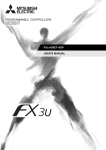
(3) Example of changing the head module:
1.
In GX Works2, read the parameters written in the head module into a GX Works2 project by
selecting "Read from PLC".
[Online]
2.
[Read from PLC]
Connect GX Works2 to the master station, and stop the data link from CC-Link IE Field Network
diagnostics.
3.
From CC-Link IE Field Network diagnostics, set the head module as a temporary error invalid
station.
4.
Change the head module.
Master/local module
Master station
(Station No.0)
Local station
(Station No.1)
Head module
(Station No.2)
Replace
5.
If the new head module does not have a station number assigned to it, connect GX Works2 to the
master station, and assign a station number to the head module from CC-Link IE Field Network
diagnostics.
[Diagnostics]
[CC-Link IE Field Diagnostics]
in "Network Status"
6.
click the
select the head module with station No. not set
button.
Write the parameters read in step 1 to the new head module.
The written parameters are reflected when the power is switched off and then on, or when the head
module is reset.
[Online]
7.
8.
32
[Write to PLC]
Move the head module switch to "RUN".
Clear the temporary error invalid station setting configured in step 3.
CHAPTER 5 SYSTEM CONFIGURATION
CHAPTER 5
SYSTEM CONFIGURATION
This chapter describes system configuration using a head module. For CC-Link IE Field Network configuration, refer to
the following.
Relevant master/local module user's manual
5.1
Head Module System Configuration
The following shows system configuration using a head module.
Power supply module
Head module
I/O modules or
intelligent function
modules
5
END cover
For power supply modules, refer to the following.
MELSEC-L CPU Module User's Manual (Hardware Design, Maintenance and Inspection)
5.1 Head Module System Configuration
For I/O modules and intelligent function modules, refer to the manual for the relevant modules.
The MELSEC-L series CPU module cannot be connected to a system using a head module.
33
5.2
Applicable Systems
(1) Connectable modules and the number of modules
(a) Connectable modules
MELSEC-L series modules can be connected to the head module.
However, there are some modules that can be connected with restrictions or that can be connected but cannot
be used.
(b) Number of modules
The number of I/O modules and intelligent function modules that can be connected is 10 in total.*1*2
*1
*2
The number of modules is exclusive of the number of power supply modules and END covers.
For some intelligent function modules, one module occupies a space by two modules. For the occupied space, refer to
the user's manual for the module used before configuring a system.
Some modules have restrictions on the number of modules. The following table shows the relevant models and
the number of modules.
Module
Model
Head module
LJ72GF15-T2
CC-Link system master/local module
LJ61BT11
Number of modules
1
Up to 4
(2) Modules/unit that cannot be connected
The CPU module and the following module/unit cannot be connected to the head module.
Module/unit
Model
Branch module
L6EXB
Extension module
L6EXE
RS-232 adapter
L6ADP-R2
Display unit
L6DSPU
CC-Link IE Field Network master/local module
LJ71GF11-T2
SSCNET III/H head module
LJ72MS15
Ethernet interface module
LJ71E71-100
• Positioning modules and simple motion modules cannot be connected to the head module whose serial
number (first five digits) is "12071" or earlier.
(3) Software package
GX Works2 is required for setting and diagnosing the head module.
GX Developer is not available.
Software
Version
GX Works2
Version 1.31H or later
(4) Precautions for system configuration
(a) Rated output current (5VDC)
Configure a system so that the total current consumption may not exceed 5VDC, rated output current of the
power supply module. For specifications of the power supply module, refer to the following.
MELSEC-L CPU Module User's Manual (Hardware Design, Maintenance and Inspection)
34
CHAPTER 6 INSTALLATION AND WIRING
CHAPTER 6
INSTALLATION AND WIRING
This chapter describes the installation and wiring of modules.
6.1
Wiring Environment and Installation Position
When installing the module in a control panel, fully consider its operability, maintainability, and environmental
resistance.
6.1.1
Installation environment
Install the programmable controller according to the installation environment shown in the general specifications.
(
6
Page 24, Section 3.1)
Do not install the programmable controller to the place where:
• Ambient temperature is outside the range of 0 to 55°C;
• Ambient humidity is outside the range of 5 to 95%RH;
• Condensation occurs due to rapid temperature change;
• Corrosive gas or combustible gas is present;
• Conductive powder such as dust and iron powder, oil mist, salinity, or organic solvent is filled;
• The programmable controller is exposed to direct sunlight;
• A strong electric field or strong magnetic field is generated; and
• The programmable controller is subject to vibration and shock.
Installation position
To ensure good ventilation and ease module change, provide clearance between the module top/bottom and
structures/parts as shown below.
30mm
or more
Programmable
controller
Control
panel
Door
30mm
or more
50mm or more
*1
50mm or more
20mm or more*1
When using connectors for external devices, provide clearance of 80mm or more.
35
6.1 Wiring Environment and Installation Position
6.1.1 Installation environment
6.1.2
6.2
Installation
This section describes how to interconnect modules and how to mount them on a DIN rail.
● Modules must be mounted on a DIN rail.
● Connect an END cover on the right of the terminal module.
(1) Precautions for connecting and mounting modules
• Do not directly touch any conductive parts and electronic components of the module. Doing so can cause
malfunction or failure of the module.
• The number of times the module can be connected/disconnected is limited to 50 times. (In accordance with
IEC 61131-2) Exceeding this limit may cause malfunction.
• Do not drop or apply strong shock to the module case.
• Do not remove the printed-circuit board of the module from the case. Doing so may cause failure of the
module and/or printed-circuit board.
36
CHAPTER 6 INSTALLATION AND WIRING
6.2.1
Connecting modules
This section describes the procedure for connecting modules.
An example will show how a head module is connected to the L61P.
Shut off the external power supply for the system in all phases before connecting or disconnecting modules.
(1) Connecting modules
1.
To release the module joint levers located at the top
and bottom of the head module:
Slide the levers toward the front side of the module until
Release
they click.
6
2.
Insert the connector of the power supply module
into that of the head module so that they are
securely engaged.
To lock the module joint levers:
Slide the levers toward the back side of the module until
they click.
Make sure that the modules are securely connected.
(2) Disconnecting modules
Disconnect the modules by reversing the procedure above.
● Failure to securely lock the module joint levers until they click may cause malfunction, failure, or drop of the module.
● The metal on the back of the module may be at a high temperature immediately after the module is powered off.
Take care to prevent a burn at module disconnection.
37
6.2 Installation
6.2.1 Connecting modules
3.
Lock
6.2.2
Mounting the modules on a DIN rail
This section describes a procedure for mounting the modules on a DIN rail.
The following method of using a DIN rail stopper is for explanation purpose only. Follow the instructions of the DIN rail
stopper used to fix the modules.
(1) Mounting procedure
1.
Pull down all DIN rail hooks on the back of the
modules.
The levers should be pulled down until you hear them
click.
2.
Hang the upper tabs of the modules on a DIN rail,
and push the modules in position.
3.
Lock the DIN rail hooks to the DIN rail to secure the
modules in position.
Push each hook up until you hear it click.
If the hooks are beyond the reach, use a tool such as a
driver.
4.
38
Loosen the screw of the DIN rail stopper.
CHAPTER 6 INSTALLATION AND WIRING
5.
Hitch the bottom hook of the DIN rail stopper to the
bottom of the DIN rail.
Hitch the hook according to the orientation of the arrow
on the front of the stopper.
Hitch the hook to
bottom of the DIN rail
Hitch the hook to
top of the DIN rail
6.
top of the DIN rail.
7.
DIN rail
stopper
Hitch the upper hook of the DIN rail stopper to the
Slide the DIN rail stopper up to the left side of the
6
modules.
8.
DIN rail
stopper
Push the stopper in the direction opposite from the
direction of the arrow incised on the stopper. Then
DIN rail
stopper
9.
Attach a DIN rail stopper on the right of the modules
with the same procedure. Note that a DIN rail
stopper is attached upside down.
39
6.2 Installation
6.2.2 Mounting the modules on a DIN rail
tighten the screw with a driver.
Do not slide modules from the edge of the DIN rail when mounting them. Doing so may damage the metal part located on the
back of the module.
(2) Removal procedure
Remove the modules from the DIN rail by reversing the above procedure.
(3) Applicable DIN rail model (IEC 60715)
• TH35-7.5Fe
• TH35-7.5Al
• TH35-15Fe
(4) DIN rail stopper
Use a stopper that is attachable to the DIN rail.
(5) Interval between DIN rail mounting screws
To ensure the strength of a DIN rail, tighten DIN rail mounting screws (obtained by user) within 30mm away from
the both edges of the DIN rail and at 200mm-interval between the screws.
DIN rail mounting screw
(obtained by user)
DIN rail
35mm
30mm
or less
P
P
P
30mm
or less
P=200mm or less
40
CHAPTER 6 INSTALLATION AND WIRING
6.2.3
Changing modules on a DIN rail
This section describes a procedure for changing modules on a DIN rail by sliding them rightward.
Remove the mounted terminal block and disconnect the connectors beforehand.
1.
2.
Remove the DIN rail stopper on the right edge.
Pull down DIN rail hooks on the back of the
modules.
Pull down the DIN rail hooks on the module to be
changed and the module on its right, until you hear them
click.
If the hooks are beyond the reach, use a tool such as a
driver.
3.
Release the module joint levers on the modules.
6
Slide the module joint levers on the module to be
Module to be replaced
changed and on the module on the right of the changed
module toward the front side of the module until they
click.
Disconnect the modules by sliding them
6.2 Installation
6.2.3 Changing modules on a DIN rail
4.
individually.
5.
Change the modules.
41
6.
Slide the modules and plug the connectors.
7.
Lock the module joint levers.
Slide the levers toward the back side of the module until
they click.
8.
Lock the DIN rail hooks and attach the DIN rail
stopper.
(
Page 38, Section 6.2.2)
Do not slide modules from the edge of the DIN rail when mounting them. Doing so may damage the metal part located on the
back of the module.
42
CHAPTER 6 INSTALLATION AND WIRING
6.3
Wiring to the Power Supply Modules
For information on wiring to the power supply modules, refer to the following.
MELSEC-L CPU Module User's Manual (Hardware Design, Maintenance and Inspection)
6.4
Testing the Head Module Before Wiring
(1) Unit test
Run a unit test to check if there is any abnormality in the head module hardware.
1.
2.
Power off the head module.
Connect the PORT1 and PORT2 of the head module
with an Ethernet cable.
6
Ethernet cable
Power on the head module.
Using the switch on the head module, repeat 3
cycles of STOPRESET/TESTSTOP, taking less
than 1 second per cycle. (The MODE LED flashes
Switch
after the 3rd cycle.)
: Flashing
5.
1 second or more
Hold the switch on the front of the head module in
the RESET/TEST position for 1 second or more.
Switch
43
6.3 Wiring to the Power Supply Modules
Repeat at intervals of less than 1s.
3.
4.
6.
: On
Unit test begins.
The MODE LED starts flashing, and the ×1 or ×10 LED
: Flashing
starts turning on and off repeatedly in the sequence
12481... and so on.
7.
When completed
The ×1 or ×10 LED stops turning on and off, and the
D LINK LED turns on when the test is completed.
: On
: Flashing
• When completed
The D LINK LED turns on, and the ERR. LED remains off.
• When failed
The following LEDs turn on.
• Either the ×1 or ×10 LED
• ERR. LED
• D LINK LED
If the test fails, replace the Ethernet cable and run the
test again. If the test fails again, it may be due to a
hardware failure in the head module.
When failed
Please consult your local Mitsubishi representative.
: On
: Flashing
44
CHAPTER 6 INSTALLATION AND WIRING
6.5
Wiring to the Head Module
This section describes the wiring to the head module.
6.5.1
Wiring
This section describes cable wiring and precautions. For network configuration, cables, and hubs for wiring, refer to
the following.
User's manual for the master/local module used
(1) Connecting the Ethernet cable
(a) Connecting the cable
1.
Power off the device to connect and the head
6
module.
2.
Push the Ethernet cable connector into the head
module until it clicks. Pay attention to the
connector's direction.
Power on the head module.
Power on the external devices connected to PORT1
and PORT2 of the head module.
5.
Check if the LINK LED on the port into which the
L ER
Ethernet cable is connected is on. The time between
P1
the power-on and the LINK LED turning on may
LINK
vary. The LINK LED usually turns on in a few
seconds. Note, however, that the time maybe
extended further if the linkup process is repeated
depending on the status of the device on the line. If
the LINK LED does not turn on, refer to the
troubleshooting section and take corrective actions.
(
Page 89, Section 11.4)
45
6.5 Wiring to the Head Module
6.5.1 Wiring
3.
4.
It is not necessary to distinguish between PORT1 and PORT2.
• When using only one connector in star topology, either PORT1 or PORT2 can be connected.
Either port can be used.
• When using two connectors for line topology and ring topology, an Ethernet cable can be connected to the
connectors in any combination. For example, the cable can be connected between PORT1s and between PORT1
and PORT2.
Connection between
PORT1s or PORT2s
Connection between
PORT1 and PORT2
(b) Disconnecting the cable
1.
Power off the device to connect and the head
module.
2.
46
Press the latch down and unplug the Ethernet cable.
CHAPTER 6 INSTALLATION AND WIRING
6.5.2
Grounding
Observe the following:
• Provide independent grounding when possible. Ground the FG and LG terminals to the protective ground
conductor dedicated to the programmable controller.
• If independent grounding cannot be provided, employ (2) Shared grounding shown below.
Programmable
controller
Another
equipment
Grounding
(1) Independent grounding
Programmable
controller
Another
equipment
Programmable
controller
Another
equipment
Grounding
Best
(2) Common grounding
Good
(3) Joint grounding
Not allowed
• Use thick cables up to 2mm2. Bring the grounding point close to the programmable controller as much as
possible so that the ground cable can be shortened.
6
6.5 Wiring to the Head Module
6.5.2 Grounding
47
6.5.3
Precautions
This section describes wiring precautions.
(1) Laying Ethernet cables
• Place the Ethernet cable in a duct or clamp them. If not, dangling cable may swing or inadvertently be pulled,
resulting in damage to the module or cables or malfunction due to poor contact.
• Do not touch the core of the connector of the cable or the module, and protect it from dirt and dust. If any oil
from your hand, or any dirt or dust sticks to the core, it can increase transmission loss, causing data link to
fail.
• Check the following:
• Is any Ethernet cable disconnected?
• Does any Ethernet cable short?
• Are the connectors securely connected?
(2) Broken cable latch
Do not use Ethernet cables with broken latches. Doing so may cause the cable to unplug or malfunction.
(3) Connecting and disconnecting the Ethernet cable
Hold the connector part when connecting and disconnecting the Ethernet cable. Pulling the cable connected to
the module may result in damage to the module or cable or malfunction due to poor contact.
(4) Connectors without Ethernet cable
To prevent dust from entering the module, attach the provided connector cover.
(5) Maximum station-to-station distance (Maximum Ethernet cable length)
The maximum station-to-station distance is 100m. However, the distance may be shorter depending on the
operating environment of the cable. For details, contact the manufacturer of the cables used.
(6) Bending radius of the Ethernet cable
There are restrictions on the bending radius of the Ethernet cable. Check the bending radius in the specifications
of the Ethernet cables used.
48
CHAPTER 7 PARAMETER SETTING
CHAPTER 7
PARAMETER SETTING
This chapter describes parameter settings of a head module and modules connected to the head module.
Open the setting screens by the following operation.
Project window
[Parameter]
[PLC Parameter]
7
Double-click.
● Set parameters for the entire network (the number of slave stations, link device assignment, reserved station
specification, and temporary error invalid station setting) to the master station. For details, refer to the following.
Relevant master/local module user's manual
● Routing parameters, used for communications with other networks, need not to be set to the head module.
Communications with other networks are performed according to routing parameters set to the master station.
49
7.1
PLC Parameters
This section describes the setting screens and the descriptions of PLC parameters.
Setting screen
Description
Communication Head
Set parameters to connect the head module to a CC-Link IE Field
Setting
Network.
PLC Name
Set the label and comment of the head module.
Parameter No.*1
Reference
01F0H
Page 51, Section 7.1 (1)
0000H, 0001H
Page 52, Section 7.1 (2)
PLC System
Set parameters for a system including the head module.
1002H
Page 53, Section 7.1 (3)
PLC RAS
Set parameters for the RAS function.
300AH
Page 54, Section 7.1 (4)
500FH
Page 55, Section 7.1 (5)
Set parameters to transfer data stored in the following head
module devices as cyclic data.
• Link special relay (SB)
Operation Setting
• Link special register (SW)
• Special relay (SM)
• Special register (SD)
• Link register (W)
0400H,
I/O Assignment
Set connection status of each module.
0403H to 0405H,
0409H
*1
50
Parameter numbers are used to identify a location where a parameter error has occurred.
Page 59, Section 7.1 (6)
CHAPTER 7 PARAMETER SETTING
(1) Communication Head Setting
Set parameters to connect the head module to a CC-Link IE Field Network.
Project window
[Parameter]
[PLC Parameter]
"Communication Head Setting"
7
7.1 PLC Parameters
The following table shows setting items.
Item
Description
Setting range
Online/Offline
(Default: Online)
Mode
Select a head module mode.
Network No.
Enter the network number of the head module.
• Blank*1
• 1 to 239
• (Default: Blank)
Station No.
Enter the station number of the head module.
• Blank*1
• 1 to 120
• (Default: Blank)
Hold (Store in flash ROM) PLC
diagnostic error history and
system error history by POWEROFF/RESET.
*1
Select whether to hold PLC diagnostic results and system error history data after
the head module is powered off or is reset.
Clearing the checkbox will delete data displayed in the "PLC diagnostics" dialog
box and the "Error History" dialog box when the head module is powered off or is
reset. (
Selected/not selected
(Default: Selected)
Page 84, Section 11.2 (1) (a), Page 87, Section 11.3)
When the "Network No." and "Station No." fields are left blank in online mode, the head module with the station number
set in CC-Link IE Field Network diagnostics for the master station will operate. For details, refer to "Procedure for
Changing the Head Module". (
Page 30, Section 4.2)
51
(2) PLC Name
Set the label and comment of the head module.
Project window
[Parameter]
[PLC Parameter]
"PLC Name"
The following table shows setting items.
Item
Description
Setting range
Label
Enter the label (name or application) of the head module.
Up to 10 characters
(Default: Blank)
Comment
Enter the comment of the head module.
Up to 64 characters
(Default: Blank)
52
CHAPTER 7 PARAMETER SETTING
(3) PLC System
Set parameters for a system including the head module.
Project window
[Parameter]
[PLC Parameter]
"PLC System"
7
7.1 PLC Parameters
The following table shows a setting item.
Items other than "Remote Reset" cannot be set to the head module.
Item
Remote Reset
Description
Allow
*1
Select whether to allow GX Works2 to perform remote reset to the head module.
Setting range
Selected/not selected
(Default: Selected*1)
The default differs from that of the CPU module. Note that when remote reset is performed to all stations.
53
(4) PLC RAS
Set parameters for the RAS function.
Project window
[Parameter]
[PLC Parameter]
"PLC RAS"
The following table shows a setting item.
Items other than "Module Error History Collection (Intelligent Function Module)" cannot be set to the head
module.
Item
Module Error History
Collection (Intelligent
Function Module)
54
Collection of intelligent
function module error
histories is valid.
Description
Select whether to collect errors occurred in an intelligent
function module with the head module.
Setting range
Selected/not selected
(Default: Selected)
CHAPTER 7 PARAMETER SETTING
(5) Operation Setting
Set parameters to transfer data stored in the following head module devices as cyclic data.
• Link special relay (SB)
• Link special register (SW)
• Special relay (SM)
• Special register (SD)
• Link register (W)
In Operation Setting, the following
part is configured.
Master station
RWw
Head module
RWw
W
SB/SW/SM/SD
0000H
03FFH
7
RWr
RWr
1000H
Operation setting
13FFH
7.1 PLC Parameters
1FFFH
55
Project window
[Parameter]
[PLC Parameter]
"Operation Setting"
The following table shows setting items.
Item
Assignment Method
Dev. Name
Points
56
Description
Setting range
Select a link device assignment method.
• Points/Start: Enter the points and start numbers of devices.
• Start/End: Enter the start and end device numbers.
• Points/Start
• Start/End
(Default: Start/End)
Select transfer source devices and transfer target devices.
Select "W" for either of the devices.
•W
• SB
• SW
• SM
• SD
(Default: Blank)
Enter the points of devices to be transferred.
• W: 1 to 4096
• SB: 16 to 8192
• SW: 1 to 8192
• SM: 16 to 2048
• SD: 1 to 2048
(Default: Blank)
CHAPTER 7 PARAMETER SETTING
Item
Description
Setting range
Transfer From
• W: 0 to 1FFF
• SB: 0 to 1FF0
• SW: 0 to 1FFF
• SM: 0 to 2032
• SD: 0 to 2047
(Default: Blank)
Start
Enter the start number of a device to be transferred.
Transfer To
• W: 1000 to 1FFF
• SB: 0 to 1FF0
• SW: 0 to 1FFF
• SM: 0 to 2032
• SD: 0 to 2047
(Default: Blank)
End
Enter the end number of a device to be transferred.
Transfer From
• W: 0 to 1FFF
• SB: F to 1FFF
• SW: 0 to 1FFF
• SM: 15 to 2047
• SD: 0 to 2047
(Default: Blank)
Transfer To
This item is automatically set according
to the setting of transfer source.
7
7.1 PLC Parameters
57
(a) Setting example
To transfer the link special relay (SB) data of the head module as cyclic data, transfer the link special relay (SB)
value to link register (W).
Setting for Forwarding Parameter between Devices
Transfer 1: Transfers the values in SB1040 to SB11FF to W1104 to W111F.
Transfer 2: Transfers the value in W0000 to SB1000 to SB100F.
Operation of the head module
Transfer To
Transfer From
Transfer 1
0104H
1104H
RWr
011FH
111FH
Device
name
(W)
Transfer
1
Transfer From
Device
name
(SB)
1040H
11FFH
Transfer To
Transfer 2
0000H
58
RWw
0000H
Device
name
(W)
Transfer
2
Device
name
(SB)
1000H
100FH
CHAPTER 7 PARAMETER SETTING
(6) I/O Assignment
Set connection status of each module.
Project window
[Parameter]
[PLC Parameter]
"I/O Assignment"
7
7.1 PLC Parameters
The following table shows setting items.
Item
Description
Type
Select a connected module type.
Model Name
Enter the model name of the connected module when required.
Up to 16 characters
(Default: Blank)
Points
Select the occupied I/O points of a module connected to the head module.
0 Point, 16 Points, 32 Points, 64 Points,
128 Points
(Default: Blank)
Start XY
Enter the start I/O number.
0000H to 0FE0H
(Default: Blank)
I/O Assignment
button
button
Setting range
Empty, Input, Output, Intelligent
(Default: Blank)
Set intelligent function module switches.
-
Error Time
Output Mode
Select output mode in the following status:
• An error occurred in the head module.
• A data link error occurred.
Clear/Hold
(Default: Clear)
PLC
Operation
Mode at H/W
Error
If a hardware error occurs in an intelligent function module (The head module
detects SP.UNIT DOWN.), select whether to stop auto refresh of the head
module.
Stop/Continue
(Default: Stop)
I/O Response
Time
Select the response time of an input module.
1ms, 5ms, 10ms, 20ms, 70ms
(Default: 10ms)
59
7.2
Network Parameters
Set parameters of the CC-Link master/local module connected to the head module.
Project window
[Parameter]
[Network Parameter]
[CC-Link]
For network parameters (CC-Link), refer to the following.
MELSEC-L CC-Link System Master/Local Module User's Manual
Configure a CC-Link system so that the points of devices used for CC-Link communications (RX/RY/RWr/RWw) may be
within the maximum link points per station. (
Page 25, Section 3.2)
If the CC-Link points exceeds the maximum link points per station in a large-scale system, for example, a system containing
64 stations, use W as a refresh device, instead of X and Y. (
60
Page 69, Section 8.2)
CHAPTER 7 PARAMETER SETTING
7.3
Remote Password
Set a remote password to a serial communication module.
Project window
[Parameter]
[Remote Password]
7
The following table shows setting items.
Item
Description
Up to four characters (alphanumeric
characters, special symbols)
(Default: Blank)
Model Name
Select the model name of the target serial communication module.
LJ71C24
(Default: Blank)
Start XY
Enter the start I/O number of the target serial communication module.
0000H to 0FE0H
7.3 Remote Password
Enter a remote password.
Password Setting
Password Active
Module Setting
Setting range
For details on a remote password, refer to the following.
MELSEC-Q/L Serial Communication Module User's Manual (Application)
61
7.4
Intelligent Function Module Parameters
Set intelligent function module parameters.
Set the parameters in the "New Module" dialog box.
Project window
Right-click [Intelligent Function Module]
Item
Module Type
Module
Selection
Description
Setting range
Select a module type.
Module Name
Select a model name.
Mounted Slot No.
Select the number of the slot where an intelligent function module
is mounted.
Mount Position
Title Setting
[New Module]
button
Click this button to check I/O assignment setting configured in the
PLC Parameter dialog box.
Specify start XY address
Set the start I/O number.
Title
Enter a title displayed in the Project window.
Relevant intelligent function
module manual
After these settings are configured, a folder is created under the "Intelligent Function Module" folder in the Project
window.
X, Y, and W can be set as an auto refresh device.
62
CHAPTER 8 CYCLIC TRANSMISSION
CHAPTER 8
CYCLIC TRANSMISSION
This chapter describes how to perform cyclic transmission of bit and word device data of the head module.
8.1
Cyclic Transmission of Bit Device Data
The inputs (X) and outputs (Y) of the modules connected to the head module can be handled just like those of the
master station.
Master station
Head module
(Intelligent device station)
CPU module
Master
station
Head module
Input module
Device
RX
RX
X
Device
RY
RY
Output module
Intelligent
function module
8
X
Y
Y
8.1 Cyclic Transmission of Bit Device Data
63
(1) Data flow
This section describes the data flow and the setting for cyclic transmission of bit device data.
• When inputting from an intelligent device station to the master station
The input data (X) of each module connected to the head module is input to the remote input (RX) of the
master station.
• When outputting from the master station to the intelligent device station
The remote output data (RY) of the master station is output to the output (Y) of each module connected to
the head module.
Master station
0000H
Head module
Head module
Head module
Head module
Station No.1
Station No.2
Station No.3
Station No.4
RX
RX
0000H
Station
No.1
to 009FH
0100H
RX
RX
RX
0000H
0000H
0000H
007FH
003FH
003FH
03FFH
03FFH
03FFH
009FH
Station
to 017FH No.2
0180H Station
No.3
to 01BFH Station
01C0H No.4
to 01FFH
03FFH
3FFFH
0000H
RY
0000H
RY
Station
No.1
to 009FH
0100H Station
to 017FH No.2
0180H Station
No.3
to 01BFH Station
01C0H No.4
to 01FFH
0000H
RY
0000H
RY
0000H
003FH
003FH
03FFH
03FFH
RY
007FH
009FH
03FFH
03FFH
3FFFH
The I/O data flow between the master station and the head module on the station number 1 are shown in Page 65,
Section 8.1 (1) (a), Page 66, Section 8.1 (1) (b).
64
CHAPTER 8 CYCLIC TRANSMISSION
(a) Setting "0000H" for the start number of RX/RY setting for the master station and
leaving the I/O assignment setting for the head module default
Slot 0
Slot No.
Master station
RX
0000H
to 000FH
0010H
to 001FH
0020H
RX
Slot 1
Slot 2
Slot 3
0000H
0010H
0020H
0060H
16-point input module 16-point output module 64-point input module 64-point output module
Start I/O No.
Head module
Station No.1
X
X
X
0000H
000FH
0000H
000FH
0000H
X
X
0000H
0000H
003FH
003FH
Station No.1
005FH
0060H
009FH
009FH
07FFH
3FFFH
RY
0000H
to 000FH
0010H
to 001FH
0020H
0000H
RY
Y
0000H
000FH
Y
0000H
000FH
Y
0000H
003FH
Y
0000H
Y
003FH
Station No.1
005FH
0060H
009FH
009FH
8
07FFH
3FFFH
8.1 Cyclic Transmission of Bit Device Data
65
(b) Setting "0000H" for the start number of RX/RY setting for the master station and
changing the I/O assignment setting for the head module
The figure on the bottom shows assignment when I/O assignment is set as the figure below.
Slot 0
Slot No.
Master station
0000H
RX
RX
Slot 2
Slot 3
0000H
000FH
0000H
000FH
X
X
X
X
0000H
001FH
Station No.1
0020H
to 002FH
0030H
to 003FH
Slot 1
0020H
0000H
0030H
0010H
16-point input module 16-point output module 16-point input module 16-point output module
Start I/O No.
Head module
Station No.1
0000H
000FH
X
0000H
000FH
003FH
07FFH
3FFFH
RY
0000H
to 000FH
0010H
to 001FH Station No.1
0020H
003FH
0000H
003FH
07FFH
3FFFH
66
RY
Y
0000H
000FH
Y
0000H
000FH
Y
0000H
000FH
Y
0000H
000FH
Y
CHAPTER 8 CYCLIC TRANSMISSION
(2) Setting method
In Network Configuration Setting of the master station, set the total number of points for the input/output (X/Y) of
the modules connected to the head module, in 16-point units.
In the case of the diagram on the previous page, specify "0000" to "003F" for "RX/RY Setting".
● To set an empty slot in the intelligent device station or to change a start I/O number, modify the data in the I/O
Assignment setting of the head module.
8
67
8.1 Cyclic Transmission of Bit Device Data
● If the number of points will be increased for a system expansion in future, for example, set a large number for "RX/RY
Setting" in Network Configuration Setting of the master station. Doing so will eliminate the need to change parameters for
the master station at the time of the system expansion. However, increasing the number of points also increases the
processing time.
(3) Output status for each status
Depending on the states of the data link and head module, data may not be able to be output.
The following table shows how the states of the data link and head module affect the output (Y).
-: Not dependent on the status
Switch
Head Module
Data Link
Status
Status
Output (Y) Status
Varies depending on the status and setting of the master station. (
User's
manual for the master/local module used)
(1)
If the CPU module of the master station is in the stop error status:
The output (Y) status is determined by the "Error Time Output Mode" setting in
the PLC Parameter dialog box. (
Page 59, Section 7.1 (6))
The analog output status from the digital-analog converter module and the
analog I/O module is determined by the setting of the analog output
HOLD/CLEAR function.
MELSEC-L Digital-Analog Converter Module User's Manual
Cyclic
RUN
Operating normally
transmission in
progress
MELSEC-L Analog Input/Output Module User's Manual
(2)
When the CPU module on the master station is in the STOP status:
The output (Y) is determined by the refresh parameters (refresh device of RY
for the head module) of the master station.
• If "Y" is specified for the CPU side device, the output (Y) of the head module
turns off.
• If "other than Y (M, L, etc.)" is specified for the CPU side device, the output (Y)
of the head module depends on "Case of CPU STOP Setting" of the master
station.
The analog output status from the digital-analog converter module and the
analog I/O module is determined by the setting of the analog output
HOLD/CLEAR function.
MELSEC-L Digital-Analog Converter Module User's Manual
MELSEC-L Analog Input/Output Module User's Manual
The output (Y) status is determined by the "Error Time Output Mode" setting in the
Cyclic
RUN
Operating normally
transmission
stopped
PLC Parameter dialog box. (
Page 59, Section 7.1 (6))
The analog output status from the digital-analog converter module and the analog
I/O module is determined by the setting of the analog output HOLD/CLEAR function.
MELSEC-L Digital-Analog Converter Module User's Manual
MELSEC-L Analog Input/Output Module User's Manual
The output (Y) is held for 2 seconds after the module cannot be communicated with
RUN
Operating normally
Disconnected
the master station due to a cause such as disconnection of the Ethernet cable.
The output (Y) status after disconnection is determined by the "Error Time Output
Mode" setting in the PLC Parameter dialog box. (
-
Error
-
Page 59, Section 7.1 (6))
The output (Y) status is determined by the "Error Time Output Mode" setting in the
PLC Parameter dialog box. (
Page 59, Section 7.1 (6))
The analog output status from the digital-analog converter module and the analog
I/O module is determined by the setting of the analog output HOLD/CLEAR function.
STOP
Operating normally
-
MELSEC-L Digital-Analog Converter Module User's Manual
MELSEC-L Analog Input/Output Module User's Manual
The output (Y) turns off.
68
CHAPTER 8 CYCLIC TRANSMISSION
8.2
Cyclic Transmission of Word Device Data
Word data, such as a buffer memory of the module connected to the head module, can be used in the word device of
the master station.
Master station
Head module
(Intelligent device station)
CPU module
Master
station
Head module
Device
RWr
RWr
Device
RWw
RWw
Intelligent
Intelligent
function module function module
Buffer memory,
etc.
Buffer memory,
etc.
8
8.2 Cyclic Transmission of Word Device Data
69
(1) Data flow
This section describes the data flow and the setting for cyclic transmission of word device data.
• When transferring data from the master station to the intelligent device station
The remote register (RWw) data of the master station is transferred to the buffer memory of the intelligent
function module connected to the head module.
• When transferring data from the intelligent device station to the master station
The buffer memory data of the intelligent function module connected to the head module is transferred to the
remote register (RWr) of the master station.
Master station
RWw
0000H Station
to 0007H
No.1
0008H Station
No.2
to 000FH
0010H Station
No.3
to 001FH
0020H
Station
No.4
to 0037H
Head module
Head module
Head module
Head module
Station No.1
Station No.2
Station No.3
Station No.4
0000H
RWw
0007H
0000H
RWw
0000H
RWw
0000H
RWw
007FH
000FH
0017H
03FFH
03FFH
03FFH
03FFH
1FFFH
RWr
0000H Station
No.1
to 0007H
0008H Station
No.2
to 000FH
0010H Station
No.3
to 001FH
0020H
Station
No.4
to 0037H
0000H
0007H
RWr
0000H
RWr
RWr
0000H
RWr
0000H
007FH
000FH
0017H
03FFH
03FFH
03FFH
03FFH
1FFFH
The data transfer flow between the master station and the head module on the station number 1 are shown in Page 71,
Section 8.2 (1) (a).
70
CHAPTER 8 CYCLIC TRANSMISSION
(a) Setting "0000H" for the start number of RWw/RWr setting for the master station
Master station
Head module
Station No.1
RWw
0000H
to 0003H
Station No.1
0007H
W
RWw
0000H
to 0003H
Digital-analog
converter module
Buffer memory
0000H
to 0003H
0007H
0007H
03FFH
03FFH
1FFFH
0000H
0006H
0007H
RWr
Station No.1
0000H
0006H
0007H
RWr
03FFH
1000H
1006H
1007H
13FFH
8
1FFFH
1
Set RWw/RWr ranges assigned to the head module in “Network Configuration Setting” of the master station.
(
2
Page 72, Section 8.2 (2), procedure 2)
Assign 1024 points of W0 to W3FF from RWw0.
Assign 1024 points of W1000 to W13FF from RWr0.
3
Set the refresh ranges of buffer memories in the head module and the intelligent function module using auto refresh
setting. (
Page 72, Section 8.2 (2), procedure 1)
71
8.2 Cyclic Transmission of Word Device Data
1FFFH
(2) Setting method
1.
Set the auto refresh of the intelligent function module connected to the head module.
Specify the following devices as the devices to be auto refreshed.
Item
Setting range of auto refresh target device
"Transfer to PLC"
W1000 to W13FF
"Transfer to intelligent function module"
W0 to W3FF
2.
In the Network Configuration Setting of the master station, set the number of points for RWw/RWr
to be assigned to the head module.
The number of points should be higher than the number of points set in the auto refresh setting, in the step
1 above. (Set the number of points whichever is greater between "Transfer to CPU" and "Transfer to
intelligent function module".)
If the number of points will be increased for a system expansion in future, for example, set a large number for "RWw/RWr
Setting" in Network Configuration Setting of the master station. Doing so will eliminate the need to change parameters for
the master station at the time of the system expansion. However, increasing the number of points also increases the
processing time.
72
CHAPTER 9 CC-LINK IE FIELD NETWORK DIAGNOSTICS
CHAPTER 9
CC-LINK IE FIELD NETWORK
9
DIAGNOSTICS
This section describes how to check error locations and error causes by the CC-Link IE Field Network diagnostics of
GX Works2.
When GX Works2 is connected to the master station, the entire network status can be monitored. If an intelligent
device station cannot be monitored due to cable disconnection or any other error, directly connect GX Works2 to the
head module.
This chapter describes a method for diagnosing the head module by directly connecting GX Works2. When GX
Works2 is connected to the master station, refer to the following.
Relevant master/local module user's manual
9.1
Diagnostic Items
The following shows items that can be diagnosed by CC-Link IE Field Network diagnostics (when GX Works2 is
connected to the head module).
9.1 Diagnostic Items
2
1
3
Item
1
2
3
Reference
Display of head module status and error details
Page 76, Section 9.3
Communication Test
Page 78, Section 9.4
Cable Test
Page 78, Section 9.5
System Monitor
Page 79, Section 9.6
Remote Operation
Page 79, Section 9.7
73
9.2
Starting Diagnostics
This section describes how to use CC-Link IE Field Network diagnostics.
1.
2.
Connect GX Works2 to the head module.
Start CC-Link IE Field Network diagnostics from the menu.
[Diagnostics]
[CC IE Field Diagnostics]
● When another station has been specified as a connected station
CC-Link IE Field Network diagnostics cannot be started when another station has been specified in "Other Station
Setting" of the "Transfer Setup" dialog box. In this case, directly connect GX Works2 to the head module.
● Start from the "PLC Diagnostics" dialog box
CC-Link IE Field Network diagnostics can also be started from the "PLC Diagnostics" dialog box.
1. With the mouse, select the connector to which the Ethernet cable is connected.
2. Click "CC-Link IE Field Diagnostics" appearing on the right side.
74
CHAPTER 9 CC-LINK IE FIELD NETWORK DIAGNOSTICS
3.
The head module status is displayed in "Selected Station Communication Status Monitor".
(
9
Page 76, Section 9.3)
If an error occurs, a button indicating the error (e.g.
button) is displayed. Clicking the
button allows checking of error details and corrective actions.
The status of the head module is displayed.
Click.
4.
Various tests and operations can be performed from "Operation Test" and "Selected Station
Operation" on the bottom left of the dialog box. (
Page 78, Section 9.4 to Page 79, Section 9.7)
9.2 Starting Diagnostics
Various tests and operations
can be performed.
75
9.3
Diagnostic Screen
This section describes items displayed in the "CC IE Field Diagnostics" dialog box.
(1) Displayed items
Item
Monitor
Status
76
Description
button
Starts monitoring of CC-Link IE Field Network diagnostics.
button
Stops monitoring of CC-Link IE Field Network diagnostics.
CHAPTER 9 CC-LINK IE FIELD NETWORK DIAGNOSTICS
Item
Description
9
Displays head module status.
1)
3)
2)
4)
5)
6)
Displays operating status.
Selected Station Communication Status
: Normal
1)
Monitor
: Error (Data link is continued.) (yellow)
: Error (Data link is stopped.) (red)
2)
Displays a mode.
3)
Displays a MAC address.
4)
5)
Click this button to check error details. Take corrective actions, following description
displayed in "Error Factor" and "Troubleshooting".
Displays the LED status of the head module and communication status of PORT1
and PORT2. (
Page 20, CHAPTER 2)
Displays status of the cables connected to PORT1 and PORT2.
: Normal
6)
: Error (cable disconnection)
9.3 Diagnostic Screen
: Error (other than cable disconnection)
Operation
button
Performs a communication test. (
Relevant master/local module user's manual)
Test
button
Selected
Station
button
Performs a cable test. (
Relevant master/local module user's manual)
Displays the System Monitor dialog box. (
Page 87, Section 11.3)
Performs remote operation (RUN, STOP, and RESET operations) to the head module.
Operation
button
(
Page 79, Section 9.7)
77
9.4
Communication Test
Communication test checks if transient transmission data is properly routed from the own station to the communication
target. For test method, refer to the following.
Relevant master/local module user's manual
9.5
Cable Test
Cable test checks if an Ethernet cable is properly connected. Only an Ethernet cable connected to the PORT1 or
PORT2 of the target station is tested. For test method, refer to the following.
Relevant master/local module user's manual
78
CHAPTER 9 CC-LINK IE FIELD NETWORK DIAGNOSTICS
9.6
System Monitor
9
The "System Monitor" dialog box can be displayed. In the dialog box, errors that occur in a module other than the head
module can also be checked. For system monitor, refer to
9.7
Page 87, Section 11.3.
Remote Operation
Remote operation (RUN, STOP, and RESET operations) can be performed from GX Works2 to the head module.
1.
2.
Connect GX Works2 to the head module.
Start CC-Link IE Field Network diagnostics from the
[Diagnostics]
3.
[CC IE Field Diagnostics]
Click the
button in the "CC IE
Field Diagnostics" dialog box.
The "Remote Operation" dialog box opens.
4.
Select a remote operation to the head module in
"Operation".
Item
RUN
STOP
RESET
5.
Description
Select a remote operation to the head module.
• If remote RUN is performed when the switch of the
head module is set to STOP or the master station
is in STOP status (including disconnected status),
the head module will not enter RUN status.
• If remote RESET is performed when the switch of
the head module is set to RUN, the head module
will not be reset.
Click the
button to perform the remote
operation.
79
9.6 System Monitor
menu.
CHAPTER 10 MAINTENANCE AND INSPECTION
This chapter describes items that must be maintained or inspected daily or periodically to properly use a
programmable controller in optimal condition at all times.
10.1
Daily Inspection
This section describes items that must be inspected daily.
Check box
The modules are securely installed.
The module joint levers are properly locked.
The terminal screws of the modules are properly tightened.
Solderless terminals are physically out of contact and away from each other.
Cable connectors are fully inserted.
The terminal cover of the power supply module is securely attached.
80
CHAPTER 10 MAINTENANCE AND INSPECTION
10.2
Periodic Inspection
This section describes items that must be inspected once or twice every 6 to 12 months.
The items must be inspected as well when the equipment has been relocated or modified, or wiring layout has been
10
changed.
Check box
The ambient temperature is within 0 to 55 C.
The ambient humidity is within 5 to 95%RH.
There is no corrosive gas.
The voltage across 100VAC terminals is within 85V to 132VAC.
The voltage across 200VAC terminals is within the range of 170V to 264VAC.
The voltage across 24VDC terminals is within 15.6V to 31.2VDC.
The modules are securely installed.
No dust or foreign matter is present.
No error has occurred.
10.2 Periodic Inspection
81
CHAPTER 11
TROUBLESHOOTING
This chapter describes errors that may occur in the head module, causes of the errors, and corrective actions.
11.1
Before Troubleshooting
Check that the POWER LED of the power supply module is on. If it is off, troubleshoot the CPU module.
(
MELSEC-L CPU Module User's Manual (Hardware Design, Maintenance and Inspection))
11.2
Troubleshooting Procedure
The procedure for identifying the cause of the problem and taking action is explained below.
GX Works2 is used for this. When GX Works2 is connected to the master station, the entire network status can be
monitored. If the head module status cannot be monitored due to cable disconnection or any other error, directly
connect GX Works2 to the head module.
This chapter describes the troubleshooting procedure taken when GX Works2 is directly connected to the head
module.
82
CHAPTER 11 TROUBLESHOOTING
(1) Procedure
1.
Connect GX Works2 to the head module, and open
the "System Monitor" dialog box.
[Diagnostics]
[System Monitor]
11
2.
Select the module in which an error has occurred.
• When the selected module is the head module
Page 84, Section 11.2 (1) (a)
• When the selected module is any other than the head
module
Page 86, Section 11.2 (1) (b)
Network diagnostics. (
Page 73, CHAPTER 9)
83
11.2 Troubleshooting Procedure
When data link cannot be performed even though no failure is shown in "System Monitor", perform the CC-Link IE Field
(a) Checking for failure of the head module
1.
Selecting the head module in "System Monitor" and
clicking the
button will open the "PLC
Diagnostics" dialog box.
How to start CC-Link IE field network diagnostics
2.
Select the error that is occurring, and click the
button to check the cause and action.
When data link cannot be performed even though no
failure is shown in "PLC Diagnostics", open the CC-Link
IE Field Network diagnostics screen by the operation
shown left and take action.
(
1) Place the mouse pointer on
the port to be diagnosed.
2) The CC-Link IE Field Diagnostics icon appears.
Click the icon.
84
Page 73, CHAPTER 9)
CHAPTER 11 TROUBLESHOOTING
3.
Reset of the head module and errors occurred
before power off can be checked in the "Error
History" dialog box.
[Diagnostics]
[System Monitor]
button
In the single "Error History" dialog box, the error history
of the head module and intelligent function modules can
be viewed. (
4.
11
Page 87, Section 11.3)
If data link is not available even after
troubleshooting by the above operation, perform
the following.
• CC-Link IE Field Network diagnostics by connecting GX
Works2 to the master/local module (
Relevant
master/local module user's manual)
• Checking the LEDs (
Page 89, Section 11.4)
• Troubleshooting by symptom (
Page 92, Section
11.5)
11.2 Troubleshooting Procedure
85
(b) Checking for failure of a module other than the head module
1.
Select a module other than the head module in the
"System Monitor" dialog box, and click the
or
button to view the
diagnostics or detailed information.
Displays the latest
error code.
Displays the
error history.
Displays the details
and solution of the
error code that is
selected in the error
history.
2.
Reset of the head module and errors occurred
before power off can be checked in the "Error
History" dialog box.
[Diagnostics]
[System Monitor]
button
In the single "Error History" dialog box, the error history
of the head module and intelligent function modules can
be viewed. (
3.
Page 87, Section 11.3)
If data link is not available even after
troubleshooting by the above operation, perform
the following.
• Checking the LEDs (
Page 89, Section 11.4)
• Troubleshooting by symptom (
11.5)
86
Page 92, Section
CHAPTER 11 TROUBLESHOOTING
11.3
System Error History
The history of the errors that occurred in the past can be checked so that corrective actions can be taken for each of
them. Reset of the head module and errors occurred before power off can be also checked. On a single screen, error
history of not only the head module but also the intelligent function modules installed with the head module can be
checked.
Data of up to 100 errors can be collected. (Once the number of collected error logs exceeds 100, the oldest error logs
11
will be deleted.)
Head module
Module A
Module B
GX Works2
Error history display
Time
19:29
19:33
19:34
19:36
Module
Module A
Head module
Module B
Module A
Error code
A1
C1
B1
A2
Error history of the head module and intelligent
function modules connected to the head module
(1) Checking the error history
1.
Open the "Error History" dialog box.
[Diagnostics]
[System Monitor]
button
The error history is displayed. Check the error and
solution and troubleshoot the problem.
Displays the details and solution of the error selected in "Error History List."
● If error code 9900 is detected, check the error and solution of error code D***H detected at the same time to troubleshoot
the problem. Concurrently with error code 9900, error code D***H is also detected.
● If the same error occurred continuously, only the first error record is displayed in the "Error History" dialog box.
● Selecting a module in the "Main Block" area in "System Monitor" and clicking the
button will also open
the "Error History" dialog box. In this case, only the error history of the module selected in "Main Block" is displayed.
For details on errors of intelligent function modules, refer to the following.
Relevant intelligent function module manual
87
11.3 System Error History
Displays the error history of the module.
(2) Precautions
(a) The time and date of the error is not correctly displayed.
• Check if the master station is connected to the head module. The head module periodically collects time
information from the CPU module on the master station. If the master station is not connected to the head
module, the time and date of errors will not be displayed correctly. (Initial value: 2000/01/01 00:00:00)
• After acquisition of clock information from the master station, if the head module is powered off and then
on, the clock will restart from the time of the power off. (The clock pauses during power off.)
Because of this, the displayed time and date of the error occurred during initial processing may be different
from the actual time and date.
(b) The error code is not correctly displayed.
If errors occurred frequently, "*HST.LOSS*" may be displayed in the "Error Code" column, instead of an error
code.
(c) No error history is displayed.
In "PLC RAS" of PLC Parameter, check if the "Module Error History Collection (Intelligent Function Module)" is
selected. This setting is enabled by performing "Write to PLC" in GX Works2 and resetting the head module or
turning off and then on the power.
Select the
checkbox.
If the check box in "Module Error History Collection (Intelligent Function Module)" is cleared, error history data of intelligent
function modules are not collected.
Clear the check box if a higher operation speed is desired for the head module.
88
CHAPTER 11 TROUBLESHOOTING
11.4
Checking the LEDs
The following explains how to troubleshoot the system by the LEDs.
(1) When the RUN LED turned off
Check item
Is the head module installed correctly?
Action
11
Connect the head module to the power supply module again.
If the above action does not solve the problem, perform the unit test on the head module to check for a hardware
error. (
Page 43, Section 6.4)
(2) When the RUN LED is flashing
Check item
Is the switch of the head module set to RUN?
Is it in the remote STOP status?
Has an error occurred in the head module?
Action
Set the switch of the head module to RUN to start data link.
Cancel the remote STOP and start data link.
From "System Monitor" in GX Works2, identify the cause of the error and
take action. (
Page 82, Section 11.2)
Place the master station into the RUN state. If the master station has
Is the master station in the RUN state?
stopped due to an error, troubleshoot it referring to the manual for the
master station. (
Relevant master/local module user's manual)
• Place the master station into the RUN state and reconnect the head
Was the head module disconnected during STOP of the master
station?
module to the network.
• Reset the head module because it retains the STOP status of the
master station.
Check item
Is the mode of the head module set to Online?
Action
Change the mode of the head module to Online. (
Page 51,
Section 7.1 (1))
If the above action does not solve the problem, perform the unit test on the head module to check for a hardware
error. (
Page 43, Section 6.4)
(4) When the MODE LED is flashing
Check item
Is the head module in preparation for the unit test?
Is the head module in execution of the unit test? (The ×1 or ×10
LED is flashing.)
Action
If the switch on the head module was repeatedly switched between
STOP and RESET/TEST, reset the head module and start the unit test.
The head module is in execution of the unit test. When the unit test is
terminated, the D LINK LED turns on. Take action according to the unit
test result. (
Is the mode of the module on the master station set to Online?
Page 43, Section 6.4 (1))
Change the mode of the module to Online. (
Relevant master/local
module user's manual)
If the above actions do not solve the problem, perform the unit test on the head module to check for a hardware
error. (
Page 43, Section 6.4)
89
11.4 Checking the LEDs
(3) When the MODE LED turned off
(5) When the D LINK LED turned off
Check item
Action
• If an error has occurred in the CPU module of the master station,
remove the cause of the CPU module error. (
Is the master station connected to the network and operating
Relevant
master/local module user's manual)
normally?
• Connect GX Works2 to the master station, and check if the master
station is performing data link by CC-Link IE Field Network
diagnostics. (
Relevant master/local module user's manual)
• Check if 1000BASE-T-compliant Ethernet cables are used.
(
Does Ethernet cables normally operate?
Page 25, Section 3.2)
• Check if the station-to-station distance is 100m or less.
(
Page 48, Section 6.5.3)
• Check if the Ethernet cables are not disconnected.
Are the switching hub and other stations connected to the head
module normal?
Check if the switching hub and other stations are powered on.
Check if a 1000BASE-T-compliant switching hub is used.
Does the switching hub normally operate?
(
Isn't the station number of the head module duplicated with any
of other stations?
Relevant master/local module user's manual)
Change the duplicated station number.
Does the network No. of the head module match the number of
Change the network No. of the head module to the number of the
the connected network?
connected network.
If the above actions do not solve the problem, perform the following tests on the head module to check for an error.
• Unit test (
• Cable test (
Page 43, Section 6.4)
Page 78, Section 9.5)
(6) When the D LINK LED is flashing
Check item
Action
• Have the station number of the actual head module and the one
Are the STATION NO. LEDs of the head module correctly
showing the station number specified in Network Configuration
Setting of the master station?
specified in Network Configuration Setting of the master station
matched.
• In GX Works2, format the PLC memory of the head module and then
write PLC parameters again.
If the above actions do not solve the problem, connect GX Works2 to the master station and perform the CC-Link
IE Field Network diagnostics. (
Relevant master/local module user's manual)
(7) When the ERR. LED turned on
Identify the cause of the error in GX Works2 and take action. (
90
Page 82, Section 11.2)
CHAPTER 11 TROUBLESHOOTING
(8) When the L ERR. LED turned on
Check item
Action
• Check if 1000BASE-T-compliant Ethernet cables are used.
(
Does Ethernet cables normally operate?
Page 25, Section 3.2)
• Check if the station-to-station distance is 100m or less.
(
Page 48, Section 6.5.3)
11
• Check if the Ethernet cables are not disconnected.
• Check if a 1000BASE-T-compliant switching hub is used.
Does the switching hub normally operate?
(
Relevant master/local module user's manual)
• Check if the switching hub is on.
Do other stations connected to the head module normally
operate?
Is the mode of the module on the master station set to Online?
Is there any noise affecting the system?
Check if the systems on other stations are on.
Change the mode of the module to Online. (
Relevant master/local
module user's manual)
Check the wiring condition.
When the loopback function is enabled, check if the ring topology is
Is the loopback function enabled for the master station?
correctly configured for the port where the L ERR. LED is on.
(
Relevant master/local module user's manual)
If the above actions do not solve the problem, perform the following tests on the head module to check for an
error
• Unit test (
• Cable test (
Page 43, Section 6.4)
Page 78, Section 9.5)
(9) When the LINK LED turned off
11.4 Checking the LEDs
Check item
Action
• Check if 1000BASE-T-compliant Ethernet cables are used.
(
Does Ethernet cables normally operate?
Page 25, Section 3.2)
• Check if the station-to-station distance is 100m or less.
(
Page 48, Section 6.5.3)
• Check if the Ethernet cables are not disconnected.
Are the switching hub and other stations connected to the head
module normal?
Check if the switching hub and other stations are powered on.
If the above actions do not solve the problem, perform the following tests on the head module to check for an
error.
• Unit test (
• Cable test (
Page 43, Section 6.4)
Page 78, Section 9.5)
(10)When the REM. LED is flashing
Check item
Action
After execution of "Write to PLC", was the head module reset?
Reset the head module.
Are any forced I/O data being registered?
Cancel the registration.
(11)When the REM. LED turned off
Check item
Has an error occurred in the head module?
Action
From "System Monitor" in GX Works2, identify the cause of the error and
take action. (
Page 82, Section 11.2)
91
11.5
Troubleshooting by Symptom
Troubleshooting methods are described by symptom. Perform these troubleshooting actions when cyclic and/or
transient transmissions are not possible with the target station even though no error is detected in the head module.
If an error has occurred in an intelligent function module installed with the head module, identify the cause of the error
by GX Works2. (
Page 82, Section 11.2)
● Before starting the troubleshooting by symptom, check that the POWER LED of the power supply module is on.
For troubleshooting of the power supply module, refer to the
Design, Maintenance and Inspection).
MELSEC-L CPU Module User's Manual (Hardware
● When the troubleshooting by symptom cannot solve the problem
Perform the unit test on the head module to check for a hardware error. (
11.5.1
Page 43, Section 6.4)
Cyclic transmission cannot be performed.
When cyclic data are not delivered to other stations, or when cyclic data from the master station cannot be received, use the following
troubleshooting methods.
Check item
Action
If the D LINK LED is flashing or off, perform the troubleshooting by the
Is the D LINK LED of the head module on?
LEDs. (
Are the I/O assignment settings of PLC parameter correct?
Is the switch of the head module set to "RUN"?
Page 89, Section 11.4)
Set the I/O assignment correctly. (
Page 59, Section 7.1 (6))
Set the switch of the head module to "RUN".
If the RUN LED is flashing or off, perform the troubleshooting by the
Is the RUN LED of the head module on?
LEDs. (
Page 89, Section 11.4)
If the above actions do not solve the problem, check the link device assignment of the master station and the refresh
target device setting of refresh parameters for an error. (
11.5.2
Relevant master/local module user's manual)
Transient transmission cannot be performed.
If transient transmissions are not executable with the target station, check if the network number and station number of
the head module are set. (
Page 51, Section 7.1 (1))
If network number and station number are set for the head module, refer to the troubleshooting pages written for the
master/local module, and take action. (
92
Relevant master/local module user's manual)
CHAPTER 11 TROUBLESHOOTING
11.6
Error Code List
This section describes error messages, error conditions, causes, and actions for respective error codes of the head
module.
Errors of the head module are classified by error codes as shown below.
Error code
Classification
Reference
1 to 10000
Errors of the head module
Page 94, Section 11.6 (1)
4000H to 4FFFH
Error codes returned to the request source at communications
Page 100, Section 11.6 (2)
D000H to DFFFH
Errors of the CC-Link IE Field Network
Page 100, Section 11.6 (3)
11
11.6 Error Code List
93
(1) Error code list (1 to 10000)
The following lists the error messages, error conditions, causes, and actions of the error codes (1 to 10000).
The "■Supplementary information" in the "Error and cause" column can be confirmed by any of the following.
• PLC Diagnostics in GX Works2
• Common error information (SD5 to SD15)
• Individual error information (SD16 to SD26)
Error
code
Error and cause
Action
1000
1001
[HEAD UNIT DOWN]
The head module is running away or faulty.
• Malfunction due to noise
• Hardware failure
■Supplementary information
• Common information: • Individual information: ■Diagnostic timing
• Any time
Take action against noise, and reset the module.
If this error occurs again, the hardware of the head module may be faulty.
(Please consult your local Mitsubishi representative.)
[HEAD UNIT DOWN]
The head module is running away or faulty.
• Malfunction due to noise
• Hardware failure
■Supplementary information
• Common information: • Individual information: Breakdown information
■Diagnostic timing
• Any time
Take action against noise, and reset the module.
If this error occurs again, the hardware of the head module may be faulty.
(Please consult your local Mitsubishi representative.)
[RAM ERROR]
The RAM built in the head module is faulty.
■Supplementary information
• Common information: • Individual information: ■Diagnostic timing
• When powered on or reset
Take action against noise, and reset the module.
If this error occurs again, the hardware of the head module may be faulty.
(Please consult your local Mitsubishi representative.)
1161
[RAM ERROR]
The data in the device memory built in the head module were
overwritten.
■Supplementary information
• Common information: • Individual information: ■Diagnostic timing
• Any time
Take action against noise, and reset the module.
If this error occurs again, the hardware of the head module may be faulty.
(Please consult your local Mitsubishi representative.)
1310
[I/O INT. ERROR]
An interrupt occurred even though there is no module that can
issue an interrupt.
■Supplementary information
• Common information: • Individual information: ■Diagnostic timing
• When an interrupt occurred
The hardware of any of the installed modules is faulty. Check the installed
modules, and replace the faulty module. (Please consult your local Mitsubishi
representative.)
1311
[I/O INT. ERROR]
An interrupt request from a module installed with the head
module was detected.
■Supplementary information
• Common information: • Individual information: ■Diagnostic timing
• When an interrupt occurred
The hardware of any of the installed modules is faulty. Check the installed
modules, and replace the faulty module. (Please consult your local Mitsubishi
representative.)
1002
1003
1004
1005
1006
1009
1035
1090
1101
1102
1103
1104
94
CHAPTER 11 TROUBLESHOOTING
Error
code
Error and cause
Action
Reset the head module.
If this error occurs again, the hardware of the head module, I/O module,
intelligent function module, or END cover may be faulty.
(Please consult your local Mitsubishi representative.)
1403
[SP. UNIT DOWN]
• No response is returned from the intelligent function module.
• An error occurred in an intelligent function module was
detected.
• Any of the I/O modules (including intelligent function modules)
is being disconnected during its operation, or was
disconnected.
■Supplementary information
• Common information: Module No. (Slot No.)
• Individual information: ■Diagnostic timing
• Any time
Reset the head module.
If this error occurs again, the hardware of the head module, I/O module,
intelligent function module, or END cover may be faulty.
(Please consult your local Mitsubishi representative.)
1500
[AC/DC DOWN]
• Momentary supply power failure occurred.
• The supply power turned off.
■Supplementary information
• Common information: • Individual information: ■Diagnostic timing
• Any time
Check the supply power.
1610
[FLASH ROM ERROR]
The number of writes to the flash ROM exceeded 100,000 times.
(Number of writes > 100,000)
■Supplementary information
• Common information: • Individual information: ■Diagnostic timing
• When writing data to ROM
1700
[BUS TIMEOUT ERR.]
Failure of the system bus was detected.
■Supplementary information
• Common information: • Individual information: ■Diagnostic timing
• Any time
1710
[UNIT BUS ERROR]
• Failure of the system bus was detected.
• Failure of a connected module was detected.
■Supplementary information
• Common information: • Individual information: ■Diagnostic timing
• Any time
11
• Replace the head module.
• In "Communication Head Setting" of PLC Parameter, clear the check box so
that data of the error history and system error history will not be held at the
time of power off or reset.
Reset the head module.
If this error occurs again, this module, I/O module, intelligent function module, or
END cover may be faulty.
(Please consult your local Mitsubishi representative.)
95
11.6 Error Code List
1401
[SP. UNIT DOWN]
• In the initial processing, no response is returned from the
intelligent function module.
• The buffer memory size of the intelligent function module is
abnormal.
• No response is returned from the intelligent function module.
• When the error occurs, the start I/O number of the
corresponding intelligent function module is stored in the
common information area.
■Supplementary information
• Common information: Module No. (Slot No.)
• Individual information: ■Diagnostic timing
• When powered on, reset, or accessing an intelligent function
module
Error
code
1720
Error and cause
[END COVER ERR.]
Failure of the END cover was detected.
■Supplementary information
• Common information: • Individual information: ■Diagnostic timing
• When powered on or reset
1730
[SYSTEM RST ERR.]
Failure of the system bus was detected.
■Supplementary information
• Common information: • Individual information: ■Diagnostic timing
• When powered on or reset
2030
[NO END COVER]
There is no END cover.
■Supplementary information
• Common information: • Individual information: ■Diagnostic timing
• When powered on or reset
2031
[NO END COVER]
There is no END cover.
■Supplementary information
• Common information: • Individual information: ■Diagnostic timing
• Any time
2040
[UNIT BAD CONNECT]
• The information is different from the I/O module information at
the time of power on.
• Any of the I/O modules (including intelligent function modules)
is being disconnected during its operation, or was
disconnected.
■Supplementary information
• Common information: Module No. (Slot No.)
• Individual information: ■Diagnostic timing
• Any time
2100
[SP. UNIT LAY ERR.]
• In "I/O Assignment" of PLC Parameter, "Intelligent" is set for
the position of an I/O module. Or vice versa.
• In "I/O Assignment" of PLC Parameter, the intelligent function
module switch setting is set for the module that does not
support it.
• In "I/O Assignment" of PLC Parameter, the number of points
smaller than that of the actual intelligent function module is
assigned.
■Supplementary information
• Common information: Module No. (Slot No.)
• Individual information: ■Diagnostic timing
• When powered on or reset
2107
[SP. UNIT LAY ERR.]
A start X/Y set in "I/O Assignment" of PLC Parameter is
overlapped with that of another module.
■Supplementary information
• Common information: Module No. (Slot No.)
• Individual information: ■Diagnostic timing
• When powered on or reset
96
Action
• Replace the END cover.
• Reset the head module.
If this error occurs again, the hardware of the head module, intelligent function
module, or END cover may be faulty.
(Please consult your local Mitsubishi representative.)
• Install an END cover.
• Check if the modules are correctly connected, referring to the configuration of
the modules in the System Monitor dialog box.
• Reset the head module.
If this error occurs again, the hardware of the head module, I/O module,
intelligent function module, or END cover may be faulty.
(Please consult your local Mitsubishi representative.)
• Read common information on the error using the programming tool, check the
module corresponding to the value (module No.) and replace the module.
• Monitor SD1400 to SD1431 on the programming tool, check the module
corresponding to the bit indicating "1", and replace the module.
• Reset the head module.
If this error occurs again, the hardware of the head module, I/O module,
intelligent function module, or END cover may be faulty.
(Please consult your local Mitsubishi representative.)
• Correct the I/O Assignment setting of PLC Parameter, according to the actual
condition of the intelligent function module(s) and head module.
• In "I/O Assignment" of PLC Parameter, delete the intelligent function module
switch settings.
Correct the I/O Assignment setting of PLC Parameter, according to the actual
condition of the intelligent function module(s) and I/O module(s).
CHAPTER 11 TROUBLESHOOTING
Error
code
2124
Error and cause
Action
[SP. UNIT LAY ERR.]
• The number of connected modules exceeded 10.
• A module is installed in the position corresponding to the I/O
points of 4096 or greater.
• A module is installed across the boundary of 4096 I/O points.
■Supplementary information
• Common information: • Individual information: ■Diagnostic timing
• When powered on or reset
• Reduce the number of connected modules to 10 or less.
• Remove the module installed in the position corresponding to the I/O points of
4096 or greater.
• Replace the end module with a module so that the number of occupied points
does not exceed 4096.
• Reset the head module.
2125
[SP. UNIT LAY ERR.]
• An inappropriate module was installed.
• No response is returned from the intelligent function module.
■Supplementary information
• Common information: Module No. (Slot No.)
• Individual information: ■Diagnostic timing
• When powered on or reset
2170
[SYSTEM LAY ERR.]
An inappropriate module was installed.
■Supplementary information
• Common information: • Individual information: ■Diagnostic timing
When powered on or reset
3000
[PARAMETER ERROR]
In PLC Parameter, the number of points for empty slots is not set
within the range allowed for the head module.
■Supplementary information
• Common information: File name/Drive name
• Individual information: Parameter No.
■Diagnostic timing
• When powered on or reset, or when writing to PLC
11
• Install an appropriate module.
• Reset the head module.
If this error occurs again, the hardware of the head module, I/O module,
intelligent function module, or END cover may be faulty.
(Please consult your local Mitsubishi representative.)
• Disconnect the inappropriate module.
• Reset the head module.
If this error occurs again, the hardware of the head module, I/O module,
intelligent function module, or END cover may be faulty.
(Please consult your local Mitsubishi representative.)
• Read detailed error information using the programming tool, and check and
correct the parameter corresponding to the value (parameter No.).
• Write the corrected parameters to the head module again, and reset or
reapply power to the head module.
If this error occurs again, the hardware of the head module may be faulty.
(Please consult your local Mitsubishi representative.)
3004
[PARAMETER ERROR]
The parameter file is incorrect.
Or, the contents of the file are not parameters.
■Supplementary information
• Common information: File name/Drive name
• Individual information: Parameter No.
■Diagnostic timing
• When powered on or reset, or when writing to PLC
Check if the type of the parameter file is shown as "***.QPA" and if the file
contains parameters.
3105
[LINK PARA. ERROR]
• Although the number of modules is set to 1 or more in Network
Parameter for CC-Link, the number of actually connected
modules is 0.
• The start I/O number set in the parameter setting is different
from the actual I/O number.
• In the Network Parameter setting for CC-Link, any of the
station types is mismatched.
■Supplementary information
• Common information: File name/Drive name
• Individual information: Parameter No.
■Diagnostic timing
• When powered on or reset
Correct the Network Parameter settings, and then write them.
If the error occurs again even after the correction, the module may be faulty.
(Please consult your local Mitsubishi representative.)
97
11.6 Error Code List
3001
[PARAMETER ERROR]
The parameters are corrupted.
■Supplementary information
• Common information: File name/Drive name
• Individual information: Parameter No.
■Diagnostic timing
• When powered on or reset, or when writing to PLC
If this error occurs again, the hardware of the head module, I/O module,
intelligent function module, or END cover may be faulty.
(Please consult your local Mitsubishi representative.)
Error
code
Error and cause
Action
3106
[LINK PARA. ERROR]
A network refresh parameter for CC-Link is out of range.
■Supplementary information
• Common information: File name/Drive name
• Individual information: Parameter No.
■Diagnostic timing
• When powered on or reset
Correct the Network Parameter settings, and then write them.
If the error occurs again even after the correction, the module may be faulty.
(Please consult your local Mitsubishi representative.)
3107
[LINK PARA. ERROR]
• The CC-Link parameter setting is not normal.
• The mode not available for the installed CC-Link module
version is set.
■Supplementary information
• Common information: File name/Drive name
• Individual information: Parameter No.
■Diagnostic timing
• When powered on or reset
Correct the parameter setting.
3300
[SP. PARA ERROR]
The start I/O number for the intelligent function module set in GX
Works2 is different from the actual one.
■Supplementary information
• Common information: File name/Drive name
• Individual information: Parameter No.
■Diagnostic timing
• When powered on or reset, or when writing to PLC
Correct the parameter setting.
3301
[SP. PARA ERROR]
• Auto refresh parameters for the intelligent function module are
out of range.
• The intelligent function module set in GX Works2 is different
from the actually installed module.
■Supplementary information
• Common information: File name/Drive name
• Individual information: Parameter No.
■Diagnostic timing
• When powered on or reset, or when writing to PLC
Correct the parameter setting.
3302
[SP. PARA ERROR]
Intelligent function module parameters are not normal.
■Supplementary information
• Common information: File name/Drive name
• Individual information: Parameter No.
■Diagnostic timing
• When powered on or reset, or when writing to PLC
Correct the parameter setting.
3400
[REMOTE PASS. ERR.]
The start I/O number of the remote password target module is
set to any other than 0000H to 0FF0H.
■Supplementary information
• Common information: • Individual information: ■Diagnostic timing
• When powered on or reset
Change the start I/O number of the target module to a number within the range
of 0000H to 0FF0H.
3401
[REMOTE PASS. ERR.]
The position specified with the start I/O number in the remote
password setting is abnormal.
• No module is installed at the position.
• An intelligent function module other than the serial
communication module is installed at the position.
■Supplementary information
• Common information: • Individual information: ■Diagnostic timing
• When powered on or reset
Install an intelligent function module that supports the remote password function
in the position specified with the I/O number in the remote password setting.
98
CHAPTER 11 TROUBLESHOOTING
Error
code
5000
5001
9900
Error and cause
[WDT ERROR]
• I/O refresh processing time exceeded 200ms. Momentary
power failure occurred frequently.
■Supplementary information
• Common information: Time (200ms)
• Individual information: Time (value actually measured)
■Diagnostic timing
• Any time
[NETWORK ERROR]
A CC-Link IE Field Network error has occurred.
■Supplementary information
• Common information: • Individual information: ■Diagnostic timing
• Any time
Action
Modify the power supply system to prevent momentary power failure.
11
• Check the detailed module failure by CC-Link IE Field Network diagnostics,
and take action according to the display.
• In the system error history of System Monitor, confirm the error code of the
network error detected at the time.
11.6 Error Code List
99
(2) Error code list (4000H to 4FFFH)
If an error occurs at communication request from a programming tool, intelligent function module, or network
system, the head module returns the error code (any of 4000H to 4FFFH) to the request source.
This error code is not stored in SD0 because the error is not the one detected by the self-diagnostic function of
the head module.
When the request source is a programming tool, a message and an error code are displayed on the programming
tool.
When the request source is an intelligent function module or network system, the head module returns an error
code to the request source.
For messages, details, causes, and actions of errors, refer to the following.
User's manual for the CPU module used (hardware design, maintenance and inspection)
(3) Error code list (D000H to DFFFH)
The following lists the error messages, error conditions, causes, and actions of the error codes (D000H to
DFFFH).
Error code
Error
Action
• If the own station, target station, or relay station is disconnected from the
network, identify the cause of the disconnection and take action.
D0A0H
Transient data transmission response
wait timeout
• When the mode of the master station is "Online (High Speed Mode)",
change it to "Online (Normal Mode)" and retry the operation.
• When the receiving station encountered overloading of transient data,
reduce the frequency of transient transmission and then retry the
operation.
• Check if the cables and the switching hub are connected properly.
• Connect the cable to the other port on the module, and retry the operation.
D0A1H
Transient data transmission
• Reduce the frequency of transient transmission, and retry the operation.
completion wait timeout
• Execute a unit test for the head module. If a failure occurs again, the
hardware of the head module may be faulty. Please consult your local
Mitsubishi representative.
D0A2H
Transient data transmission
processing wait timeout
• Reduce the frequency of transient transmission, and retry the operation.
• Check if the switching hub and the cables at the request source are
connected properly.
• If the own station, target station, or relay station is disconnected from the
network, identify the cause of the disconnection and take action.
D0A3H
Transient data transmission error
• Correct the number of the station for which transient data is to be sent, and
retry the operation.
• If the station for which transient data is to be sent is on another network,
check if the routing parameters for each station are correctly set.
• Check if the cables and the switching hub are connected properly.
• Connect the cable to the other port on the module, and retry the operation.
D0A4H to D0A6H
Transient transmission failed
• Reduce the frequency of transient transmission, and retry the operation.
• Execute a unit test for the head module. If a failure occurs again, the
hardware of the head module may be faulty. Please consult your local
Mitsubishi representative.
• Check if the cables and the switching hub are connected properly.
• Connect the cable to the other port on the module, and retry the operation.
D0A7H
Transient reception failed
• Reduce the frequency of transient transmission, and retry the operation.
• Execute a unit test for the head module. If a failure occurs again, the
hardware of the head module may be faulty. Please consult your local
Mitsubishi representative.
100
CHAPTER 11 TROUBLESHOOTING
Error code
D0E0H
Error
Station type mismatch
Action
In the network configuration settings of the master station, change the station
type of the head module to "Intelligent Device Station".
• In the network configuration settings of the master station, cancel the
D0E1H
Own station reserved
reserved station setting.
• Change the station number of the head module to a station number that is
not reserved.
D0E2H
D0E3H
Station No. already in use (own
station)
Own station No. out of range
• Set a unique station number.
• After taking the above action, power off and on all the stations where this
11
error has been detected or reset them.
Add the station information of the head module in the network configuration
settings of the master station.
• Check the network status using the CC-Link IE Field Network diagnostics
of the programming tool.
D200H
Transient data received twice
• Check if the cables and switching hub are connected properly.
• If the request source is on another network, check if the routing
parameters are correctly set.
D201H
Header information error in transient
Correct the header information at the request source, and retry the
transmission
operation.
• Reduce the frequency of transient transmission and then retry the
operation.
D202H
Send buffer full
• When the mode of the master station is "Online (High Speed Mode)",
change it to "Online (Normal Mode)" and retry the operation.
• Check if the cables and switching hub are connected properly.
D203H
D204H
D206H
D207H
D208H
D209H and D20AH
D20BH
D20CH
transmission
Network No. error in transient
transmission
Correct the read/write address at the request source, and retry the operation.
• Correct the network number at the request source, and retry the operation.
• If the request source is on another network, check if the routing
parameters are correctly set.
Target station No. error in transient
Correct the target station number at the request source, and retry the
transmission
operation.
Network No. error in transient
transmission
Invalid number of relays in transient
transmission
Network No. error in transient
transmission
• Correct the network number at the request source, and retry the operation.
• If the request source is on another network, check if the routing
parameters are correctly set.
• Change the system configuration so that the number of relay stations may
be seven or less.
• Check if the routing parameters are correctly set.
• Correct the network number at the request source, and retry the operation.
• If the request source is on another network, check if the routing
parameters are correctly set.
Target station No. error in transient
transmission
Specified master station No. error in
Correct the target station number at the request source, and retry the
transient transmission
operation.
Current master station No. error in
transient transmission
• Check the network status using the CC-Link IE Field Network diagnostics
of the programming tool.
• When the own station, target station, or relay station detected an error,
D20DH
Transient data transmission
completion wait timeout
identify the cause of the error and take action.
• Reduce the frequency of transient transmission, and retry the operation.
• When the mode of the master station is "Online (High Speed Mode)",
change it to "Online (Normal Mode)" and retry the operation.
• Check if the switching hub and the cables at the request source are
connected properly.
101
11.6 Error Code List
D205H
Read/write address error in transient
Error code
D20EH
D20FH
D210H
D211H
Error
Action
Header information error in transient
Correct the header information at the request source, and retry the
transmission
operation.
Target station No. error in transient
Check that the command can be requested to all or a group of stations at the
transmission
request source, and retry the operation.
Target station No. error in transient
Correct the header information at the request source, and retry the
transmission
operation.
Own station No. not set (dedicated
instruction)
Set the station number in the parameter setting, and retry the operation.
• Check if the switching hub and the cables at the request source are
connected properly.
D212H
Transient transmission failed
• Connect the cable to the other port on the request source, and retry the
operation.
• Reduce the frequency of transient transmission, and retry the operation.
• Correct the request command at the request source, and retry the
operation.
D213H
Transient data command error
• Check the first five digits of the serial number of the master/local module. If
the master/local module does not support the function, replace it with the
master/local module with the latest version.
Transient data length error
Correct the data length at the request source, and retry the operation.
Transient data command error
Correct the request command at the request source, and retry the operation.
Incorrect number of read/write
Correct the number of read/write device data at the request source, and retry
transient data
the operation.
D219H
Transient data attribute code error
Correct the attribute code at the request source, and retry the operation.
D21AH
Transient data access code error
Correct the access code at the request source, and retry the operation.
D214H
D216H and D217H
D218H
• A malfunction may have occurred due to noise. Check the wire and cable
distances and grounding condition of each device, and take measures
D21BH and
D21CH
Head module request error
against noise.
• Execute a unit test for the head module. If a failure occurs again, the
hardware of the head module may be faulty. Please consult your local
Mitsubishi representative.
• A cable test cannot be executed for a different network. Correct "Testing
D21DH
Network No. error in transient
transmission
Station Setting", and execute the cable test again.
• Transient data that cannot be sent to a different network were received.
Correct the network number or the target station number at the request
source, and retry the operation.
• A communication test cannot be executed on a sending (relay) station.
Correct the "Target Station" setting, and execute the communication test
D21EH
Target station No. error in transient
transmission
again.
• Transient data of the application type that cannot be executed on the own
station were received. Correct the application type or the target station
number at the request source, and retry the operation.
D21FH
D222H
Target station type error (dedicated
instruction)
Transient data command error
• The SEND instruction cannot be executed on the head module.
• Modify the program of the master and local stations so that the SEND
instruction may not be executed.
Correct the request command at the request source, and retry the operation.
• Check the network status using the CC-Link IE Field Network diagnostics
of the programming tool.
D247H
Dedicated instruction received twice
• Check if the switching hub and the cables at the request source are
connected properly.
• If the request source is on another network, check if the routing
parameters are correctly set.
D280H
102
Transient data request error
Correct the request command at the request source, and retry the operation.
CHAPTER 11 TROUBLESHOOTING
Error code
Error
Action
• Check the network status using the CC-Link IE Field Network diagnostics
of the programming tool.
D281H
Transient reception failed
• When the target station or the relay station is overloaded and cannot
receive transient data, send the data to the target/relay station after the
load on the station is reduced.
• Pause the transient transmission temporarily, and retry the operation.
D282H
Receive queue full
• Reduce the frequency of transient transmission, and retry the operation.
• If this error persists, please consult your local Mitsubishi representative.
11
• Check the network status using the CC-Link IE Field Network diagnostics
of the programming tool.
D283H
Transient transmission failed
• Connect the cable to the other port on the request source, and retry the
operation.
• Reduce the frequency of transient transmission, and retry the operation.
• Check the network status using the CC-Link IE Field Network diagnostics
of the programming tool.
D2A0H
Receive buffer full
• When the target station or the relay station is overloaded and cannot
receive transient data, send the data to the target/relay station after the
load on the station is reduced.
• Reduce the frequency of transient transmission, and retry the operation.
D2A1H
Send buffer full
• Check if the switching hub and the cables at the request source are
connected properly.
• Reduce the frequency of transient transmission, and retry the operation.
• When the mode of the master station is "Online (High Speed Mode)",
change it to "Online (Normal Mode)" and retry the operation.
D2A2H
Transmission completion wait timer
timeout
• Check if the switching hub and the cables at the request source are
connected properly.
• Correct the number of link dedicated instructions that have been
simultaneously executed within the range. (For details, refer to
master/local module used.)
D2A3H
D2A4H
D2A5H
D2A6H
D2A7H and
D2A8H
D2A9H
D2AAH
D2ABH
D2ACH
D2ADH
D2AEH
Transient data length error
Correct the number of data (frame length) at the request source, and retry
the operation.
Header information error in transient
Correct the header information at the request source, and retry the
transmission
operation.
Target station No. error in transient
Correct the target station number at the request source, and retry the
transmission
operation.
Transient data request source No.
Correct the request source number at the request source, and retry the
error
operation.
Header information error in transient
Correct the header information at the request source, and retry the
transmission
operation.
Target network No. error in transient
Correct the target network number at the request source, and retry the
transmission
operation.
Target station No. error in transient
Correct the target station number at the request source, and retry the
transmission
operation.
Request source network No. error in
Correct the network number of the request source at the request source, and
transient transmission
retry the operation.
Transient data request source No.
Correct the station number of the request source at the request source, and
error
retry the operation.
Transient data length error
Target station No. error in transient
transmission
Correct the number of data (frame length) at the request source, and retry
the operation.
• The head module received transient data addressed to a different network.
Correct the network and target station numbers, and retry the operation.
• Check if the routing parameters are correctly set.
103
11.6 Error Code List
"Precautions for link dedicated instructions" in the user's manual for the
Error code
Error
Action
• Transient data transmission addressed to the own station was requested.
D2AFH
Target station No. error in transient
transmission
Check the network number and target station number, and retry the
operation.
• Check if the routing parameters are correctly set.
• Check if the switching hub and the cables at the request source are
connected properly.
D2B0H
Transient transmission failed
• Connect the cable to the other port on the request source, and retry the
operation.
• Reduce the frequency of transient transmission, and retry the operation.
• A malfunction may have occurred due to noise. Check the wire and cable
distances and grounding condition of each device, and take measures
D501H
Communication LSI failure
against noise.
• Execute a unit test for the head module. If a failure occurs again, the
hardware of the head module may be faulty. Please consult your local
Mitsubishi representative.
• A malfunction may have occurred due to noise. Check the wire and cable
distances and grounding condition of each device, and take measures
D502H
MAC address error
against noise.
• Execute a unit test for the head module. If a failure occurs again, the
hardware of the head module may be faulty. Please consult your local
Mitsubishi representative.
• A malfunction may have occurred due to noise. Check the wire and cable
distances and grounding condition of each device, and take measures
D529H and D52AH
RAM failure
against noise.
• Execute a unit test for the head module. If a failure occurs again, the
hardware of the head module may be faulty. Please consult your local
Mitsubishi representative.
• A malfunction may have occurred due to noise. Check the wire and cable
distances and grounding condition of each device, and take measures
D52BH and
D52CH
Communication LSI failure
against noise.
• Execute a unit test for the head module. If a failure occurs again, the
hardware of the head module may be faulty. Please consult your local
Mitsubishi representative.
Data link start failed due to any of the following causes. Remove the error
cause, and retry the operation.
• Station No. not set
• Head module error
• More than one master station exists.
• Station type mismatch
D62DH
Data link start failed
• Master station lost
• Own station No. out of range
• Station No. already in use (own station)
• Own station reserved
• Parameter error
• Parameter communication in progress
• Parameters not received (master station only and no slave station exists)
• Link stop command
D62EH
D721H
D722H
104
Master station lost
Data link start/stop retry error (to
another station)
Data link start/stop retry error (to own
station)
Communications cannot be performed with the master station. Check
whether the cables are connected properly.
• Data link cannot be stopped because cyclic transmission has been
stopped.
• Data link cannot be started because cyclic transmission is in execution.
• Data link cannot be stopped because cyclic transmission has been
stopped.
• Data link cannot be started because cyclic transmission is in execution.
CHAPTER 11 TROUBLESHOOTING
Error code
Error
Station type error (station that
D725H
starts/stops data link throughout the
entire system)
D726H
Transient data command error
Action
The head module cannot start or stop data link of all or multiple stations.
Perform these operations from the master station.
Correct the request command at the request station, and retry the operation.
• Data link start was instructed from a station different from the one that had
instructed the data link stop. Instruct data link start and data link stop from
the same station.
D727H
Data link start/stop command
instructing stations different
• The method of the data link start differs from that of the data link stop.
11
Instruct the data link start using the same method as the data link stop (ex.
Data link is stopped using the CC-Link IE Field Network diagnostics, and
the data link is started using a program).
• Data link start failed. Forcibly restart the data link.
D728H
Data link start/stop command
Data link start was instructed during execution of data link. Instruct data link
instructing stations different
stop then data link start.
• Set the station or network number in the programming tool, and write the
D729H
Station No. or network No. not set
parameters.
• By online operation of the master station, set the network or station
number of the head module.
By online operation of the master station, set the network number or station
D72AH
Out-of-range station No.
number of the head module within the specified range.
Network No.: 1 to 239
Station No.: 1 to 120
• The read request by the CC-Link IE Field Network diagnostics of the
programming tool is incorrect. Close the "CC IE Field Diagnostics"
D783H and D784H
Transient data request error
window, and request it again.
• Check the read request data at the request station, and retry the
operation.
• A malfunction may have occurred due to noise. Check the wire and cable
D800H
Head module failure
against noise.
• Execute a unit test for the head module. If a failure occurs again, the
hardware of the head module may be faulty. Please consult your local
Mitsubishi representative.
D806H
Receive queue full
• Reduce the frequency of transient transmission, and retry the operation.
• Check if the cables and the switching hub are connected properly.
• A malfunction may have occurred due to noise. Check the wire and cable
distances and grounding condition of each device, and take measures
D814H
Head module failure
against noise.
• Execute a unit test for the head module. If a failure occurs again, the
hardware of the head module may be faulty. Please consult your local
Mitsubishi representative.
• A malfunction may have occurred due to noise. Check the wire and cable
distances and grounding condition of each device, and take measures
D816H
Head module failure
against noise.
• Execute a unit test for the head module. If a failure occurs again, the
hardware of the head module may be faulty. Please consult your local
Mitsubishi representative.
D81AH
Head module stop error
Check the error in the "PLC Diagnostics" window of the programming tool.
• A malfunction may have occurred due to noise. Check the wire and cable
distances and grounding condition of each device, and take measures
D827H
Communication RAM failure
against noise.
• Execute a unit test for the head module. If a failure occurs again, the
hardware of the head module may be faulty. Please consult your local
Mitsubishi representative.
105
11.6 Error Code List
distances and grounding condition of each device, and take measures
Error code
Error
Action
• Correct the data at the station that started the online test, and retry the
D902H
Incorrect online test data
operation.
• If this error persists, please consult your local Mitsubishi representative.
D903H
D905H
Communication test retry error
Communication monitoring timeout in
communication test
After completion of the communication test, retry the operation.
• Check the network status using the CC-Link IE Field Network diagnostics
of the programming tool, take action, and retry the operation.
• Check if the routing parameters are correctly set.
• Check the network status using the CC-Link IE Field Network diagnostics
of the programming tool, take action, and retry the operation.
D906H
Communication test transmission
• Reduce the frequency of transient transmission, and retry the operation.
completion wait timeout
• When the mode of the master station is "Online (High Speed Mode)",
change it to "Online (Normal Mode)" and retry the operation.
• Check if the routing parameters are correctly set.
D909H
D90AH
Header information error in transient
Correct the header information at the request source, and retry the
transmission
operation.
Communication test data received
Check the network status using the CC-Link IE Field Network diagnostics of
twice
the programming tool, take action, and retry the operation.
• Check the network status using the CC-Link IE Field Network diagnostics
D90BH
Incorrect number of stations
of the programming tool.
• If the number of slave stations per network is more than 120, reduce it to
120 or less.
• Correct the "Target Station" setting in the "Communication Test" window,
D90CH
Invalid communication test target
station
and retry the operation.
• Under "Target Station", set a station including a different CPU module from
the station set in "Connected Station (Own)".
D90DH
Cable test retry error
After completion of the cable test, retry the operation.
• A malfunction may have occurred due to noise. Check the wire and cable
distances and grounding condition of each device, and take measures
DA00H and
DA01H
Head module failure
against noise.
• Execute a unit test for the head module. If a failure occurs again, the
hardware of the head module may be faulty. Please consult your local
Mitsubishi representative.
• A malfunction may have occurred due to noise. Check the wire and cable
distances and grounding condition of each device, and take measures
DA10H to DA18H
Head module failure
against noise.
• Execute a unit test for the head module. If a failure occurs again, the
hardware of the head module may be faulty. Please consult your local
Mitsubishi representative.
• If the number of times that data were written to the flash ROM exceeded
100,000, clear the check box in "Communication Head Setting" of PLC
Parameter so that data of the error history and system error history will not
be held at the time of power off or reset.
DAF2H
Flash ROM failure
• Check the wire and cable distances and grounding condition of each
device, and take measures against noise.
• Execute a unit test for the head module. If a failure occurs again, the
hardware of the head module may be faulty. Please consult your local
Mitsubishi representative.
• A malfunction may have occurred due to noise. Check the wire and cable
distances and grounding condition of each device, and take measures
DAF3H
Flash ROM failure
against noise.
• Execute a unit test for the head module. If a failure occurs again, the
hardware of the head module may be faulty. Please consult your local
Mitsubishi representative.
106
APPENDICES
APPENDICES
Appendix 1
External Input/Output Forced On/Off
This section describes the function that forcibly turns on or off the external input/output of the head module.
(1) Input/output operation when a forced on/off operation is performed
Three types of forced on/off operations are available as shown in the following table. The following table shows
the status of input (X) and output (Y) when a forced on/off operation is performed.
Operation
Input (X) operation
A
Output (Y) operation
Forced ON registration
The remote input (RX) assigned to input (X) is
transmitted cyclically in a forced on-status.
Regardless of the remote output (RY) that was
transmitted cyclically, "ON" is output externally.
Forced OFF registration
The remote input (RX) assigned to input (X) is
transmitted cyclically in a forced off-status.
Regardless of the remote output (RY) that was
transmitted cyclically, "OFF" is output externally.
Forced on/off clear
The remote input (RX) is changed by an external
input.
The remote output (RY) of the master station is output
to the external device.
Ex. The following shows the input/output operation when a forced on/off operation is performed.
Forcibly changes the input (X)
from the input module.
CPU module
X
OFF
RX
OFF
Y
OFF
OFF
RY
OFF
OFF
Head module
RX
OFF
RY
OFF
Output
module
Forced
OFF
registration
Forced
ON
registration
Forcibly changes the output
(Y) from the master station.
Input
module
Appendix 1 External Input/Output Forced On/Off
Program
Master/local
module
Switch
ON
ON
Lamp
107
(a) Number of devices that can be registered
Up to 32 devices in total can be registered.
(b) Checking the execution status
• "Forced Input Output Registration/Cancellation" screen of GX Works2
• Flashing of the MODE LED (green) (The MODE LED flashes in green when a device is registered.)
• The on status of the 0 bit in debug function usage (SD840)
(c) Forcibly turning on/off from multiple GX Works2
Forced on/off can be registered from multiple GX Works2 to a single head module. In this case, the last
registration is effective. For this reason, the GX Works2 that executed the forced on/off may display an on/off
information that is different from that of the head module. When the forced on/off registration is performed from
multiple GX Works2, click the "
" button to update the data, and then execute the function.
(d) Status of devices after forced on/off registration data are canceled
When the on/off registration information of the following input (X) and output (Y) are canceled, the forced on/off
status is retained.
• Of the inputs (X) in the range of unattached modules, input (X) that is outside the refresh range with CCLink
• Output (Y) that is outside the range that was set in "RX/RY Setting" of Network Configuration Setting of the
master station
(e) Status of the Head Module
The REM. LED of head module flashes.
Forced on/off can be registered regardless of the RUN/STOP status.
If an error occurs in the head module, output (Y) cannot be turned on.
(f) Target input/output
• Input/output (X/Y) of the connected modules
• Input/output (X/Y) of the head module that corresponds to the refresh range of the remote I/O (RX/RY) of
the connected CC-Link master/local module.
108
APPENDICES
(2) Operating procedure
1.
Open the "Forced Input Output Registration/Cancellation" dialog box.
[Debug]
[Forced Input Output Registration/Cancellation...]
A
2.
Enter the target device to the "Device" column.
The setting range in the "Device" column is X0 to X1FFF or Y0 to Y1FFF.
3.
Button Name
Click the button for the intended operation.
Description
Button Name
Description
Registers forced on for a specified device.
Cancels forced on/off registered for the device specified.
Registers forced off for a specified device.
Cancels all forced on/off registrations.
Appendix 1 External Input/Output Forced On/Off
The latest on/off status can be checked by clicking the
button.
109
Appendix 2
File Password 32
Both read passwords and write passwords can be set to each file stored in the head module. By this function, files can
be protected against tampering and theft by a third-party.
Head module
Reading the file A
Read p
assword
GX Works2
as
Write p
GX Works2
8756
Passwo
rd
File A ca match:
n be re
ad.
sword:
Writing data to
the file A
110
: XYZ9
File A
Write password: AbcDEF12
Read password: XYZ98756
59
pQRSt6
atch:
rd mism
.
Passwo ot be written
n
n
a
c
File A
A write password and read
password can be set individually.
APPENDICES
Appendix 2.1
Setting file passwords
This section describes the characters which can be used for the password, and the types of files that can be passwordprotected.
If you forget the password, initialize the head module by formatting the PLC memory in GX Works2, and write the project to
the head module from scratch.
A
(1) Characters applicable to passwords
A read password and write password can be set individually. Alternatively, one same password can be specified
for both read and write passwords.
• Applicable characters: ASCII characters (numbers, alphabets*1, special characters*2)
• Number of characters applicable: 4 to 32 characters
*1
*2
Alphabets are case-sensitive.
Special characters are ` ~ ! @ # $ % ^ & * ( ) _ + - = { } | \ : " ; ' < > ? , . / [ ], and spaces.
(2) Timing for file protection to be enabled/disabled
Files are protected immediately after registration of a password, and the file protection is disabled immediately
after deletion of the password.
(3) Files that can be password-protected
(4) Online operations that require password authentication
Password authentication is required for the following operations whenever the file is password-protected.
(
Page 115, Appendix 2.2)
• Read from PLC (data reading)
• Write to PLC (data writing)
• Verify with PLC (data reading)
• Delete PLC Data (data writing)
• Create/Change/Delete of a password (data reading
and writing)
111
Appendix 2 File Password 32
Appendix 2.1 Setting file passwords
Passwords can be set to parameter files.
(5) Creating, changing, deleting, and canceling passwords
(a) Creating and changing
Open the "Create/Change Password" dialog box.
[Online]
[Password/Keyword]
[New...]
1.
Click the
2.
Select any of the following values for
button.
"Registration Condition".
• Read Protection
• Write Protection
• Read Protection/Write Protection
Enter password (s) and click the
button.
3.
The registration status appears as "Register".
Click the
are registered.
112
button. The passwords
APPENDICES
(b) Deleting
Open the "Delete Password" dialog box.
[Online]
[Password/Keyword]
[Delete...]
1.
Click the
button.
A
2.
Enter password (s) and click the
button.
3.
The registration status appears as "Deleted".
Click the
button. The passwords
are deleted.
113
Appendix 2 File Password 32
Appendix 2.1 Setting file passwords
(c) Disabling
Open the "Input Disable Password" dialog box.
[Online]
[Password/Keyword]
[Disable]
1.
Click the
2.
Enter password (s) and click the
button.
button.
3.
The registration status appears as "Disabled".
Click the
are disabled.
114
button. The passwords
APPENDICES
Appendix 2.2
Password authentication
The passwords can be authenticated by the following methods.
• By GX Works2
• By the MC protocol
(1) By GX Works2
1.
Whenever an online operation requiring password
authentication is executed, the "Disable Password"
A
dialog box appears.
Click the
button.
2.
Enter a password in the "Input Disable Password"
dialog box.
Appendix 2 File Password 32
Appendix 2.2 Password authentication
The entered password is valid until the project is closed.
115
(2) By the MC protocol
To access a password-protected file from the outside by using the MC protocol, the request message format of
the MC protocol must be changed and a command must be specified for the file password 32.
1.
2.
3.
Append "Keyword" at the end of the request message, and set a password in that area.
Authenticate the password using the password set to "Keyword".
For the commands requiring password authentication, specify 0004, subcommand in a request
massage, as a command for the password 32.
Function
Command (subcommand)
File delete
1822 (0004)
File attribute change
1825 (0004)
File copy
1824 (0004)
File open
1827 (0004)
For details, refer to the following.
MELSEC-Q/L MELSEC Communication Protocol Reference Manual
116
APPENDICES
Appendix 3
END Cover
This section describes the specifications of the END cover.
For specifications of the END cover with ERR terminal (L6EC-ET), refer to the following.
MELSEC-L CPU Module User's Manual (Hardware Design, Maintenance and Inspection)
(1) Part Names
A
1)
*1
1)
*1
Do not remove this label as it is for maintenance.
No.
Name
Module joint levers
Levers for connecting modules each other.
Appendix 3 END Cover
1)
Application
(2) Specifications
Item
L6EC
H
90mm
External dimensions
W
13mm
D
95mm
Internal current consumption
0.04A
Weight
0.06kg
117
Appendix 4
Link Special Relay (SB) List
The link special relay (SB) is turned ON/OFF depending on various factors occurred in data link. Any error status of the
data link can be confirmed by monitoring it.
(1) Use of the link special relays (SB)
By using the link special relays (SB), the status of the CC-Link IE Field Network can be also checked from an HMI
(Human Machine Interface), not only from GX Works2.
(2) Areas turned on/off by a user and the system
• Area turned on/off by the system: SB0000 to SB0FFF
• Area turned on/off by a user: SB1000 to SB1FFF
(3) Link special relay (SB) list
The following lists link special relays (SB).
Do not turn on/off an area whose number is not on the link special relay (SB) list.
Doing so may cause malfunction of the programmable controller system.
No.
Name
Description
Stores information on whether the module is operating with the network number and station
number set in the "Communication Head Setting" of PLC Parameter, or the module is operating
with the numbers set in the CC-Link IE Field Network Diagnostics.
OFF: Operating using the values set in "Communication Head Setting" of PLC Parameter
SB004F
Operating station number
status
ON: Operating using the values set in the CC-Link IE Field Network Diagnostics
This area is also turned ON in the following cases:
• There is no parameter in the head module.
• The "Network No." and "Station No." fields are left blank in "Communication Head Setting" of
PLC Parameter, and no station number has been set from the CC-Link IE Field Network
Diagnostics.
Stores the linkup status of PORT1 (own station).
OFF: Linkup in progress
SB006A
PORT1 linkup status
(own station)
ON: Linkdown in progress
The time that the linkup starts after power-on or Ethernet cable connection may vary. Normally, it
takes a few seconds.
Depending on device status on the line, a linkup process is repeated, resulting in the increase in
the time.
Stores the linkup status of PORT2 (own station).
OFF: Linkup in progress
SB006B
PORT2 linkup status
(own station)
ON: Linkdown in progress
The time that the linkup starts after power-on or Ethernet cable connection may vary. Normally, it
takes a few seconds.
Depending on device status on the line, a linkup process is repeated, resulting in the increase in
the time.
SB1000 to
For CC-Link master/local
By setting this as the refresh destination device of the link special relay (SB) for the CC-Link
SB1FFF
modules
master/local modules, the data link status of CC-Link can be checked.
118
APPENDICES
Appendix 5
Link Special Register (SW) List
In the link special register (SW), data link information is stored as numerical values. By monitoring it, faulty areas and
their causes can be checked.
(1) Use of the link special registers (SW)
By using the link special relays (SB), the status of the CC-Link IE Field Network can be also checked from an HMI
(Human Machine Interface), not only from GX Works2.
A
(2) Areas to which data are stored by a user and the system
• Area to which data are stored by the system: SW0000 to SW0FFF
• Area to which data are stored by a user: SW1000 to SW1FFF
(3) Link special register (SW) list
The following lists link special registers (SW).
Do not write any data to an area whose number is not on the link special register (SW) list. Doing so may cause malfunction
of the programmable controller system.
Appendix 5 Link Special Register (SW) List
119
No.
Name
SW0040
Network No.
SW0042
Station No.
Description
Stores the network number of own station.
Range: 1 to 239
Stores the station number of own station.
Range: 1 to 120 (slave stations), FFFFH (station number not set)
Stores the mode of own station.
SW0043
Mode status
0: Online
2: Offline
9: Unit test
Stores the communication status of own station.
SW0047
Baton pass status (own
station)
0: Data link in progress
2: Data link stopped, baton pass in progress
3: Baton pass stopped
5: Offline
Stores the cause of interruption in the communication (baton pass) of own station.
SW0048
Cause of baton pass
interruption
00H: In normal communication or at power-on
30H: Cable disconnection
33H: Disconnection or reconnection in progress
40H: Offline mode
Stores the cause which stopped the data link of own station.
00H: In normal communication or at power-on
01H: Stop command issued
02H: Monitoring timeout
10H: Parameter not received
11H: Own station No. out of range
SW0049
Cause of data link stop
12H: Own station specified as reserved
13H: Station No. duplication (own station)
16H: Station No. not set
18H: Parameter error
19H: Parameter communication in progress
1AH: Station type mismatch
20H: Error detected
Stores the head module status of own station.
01H: STOP (Normal)
SW004B
Module status (own
station)
02H: STOP (Stop error)
03H: STOP (Continuation error)
04H: RUN (Normal)
05H: RUN (Continuation error)
0FH: Initial processing
Stores the network number set in the CC-Link IE Field Network Diagnostics.
SW004E
1 to 239: Network No.
Station No. set for
diagnostics
SW004F
FFFFH: Station number not broadcast
Stores the station number set in the CC-Link IE Field Network Diagnostics.
1 to 120: Station No.
FFFFH: Station number not broadcast
120
APPENDICES
No.
Name
Description
Stores the connection status of own station.
00H: Normal
01H: Normal (communication in progress on PORT1, cable disconnected on PORT2)
04H: Normal (loopback communication in progress on PORT1, cable disconnected on PORT2)
SW0064
Connection status (own
10H: Normal (cable disconnected on PORT1, communication in progress on PORT2)
station)
11H: Disconnecting (cables disconnected on PORT1 and PORT2)
12H: Disconnecting (cable disconnected on PORT1, establishing line on PORT2)
21H: Disconnecting (establishing line on PORT1, cable disconnected on PORT2)
22H: Disconnecting (establishing line on PORT1 and PORT2)
40H: Normal (cable disconnected on PORT1, loopback communication in progress on PORT2)
SW1000 to
For CC-Link master/local
By setting this as the refresh destination device of the link special register (SW) for the CC-Link
SW1FFF
modules
master/local modules, the data link status of CC-Link can be checked.
A
Appendix 5 Link Special Register (SW) List
121
Appendix 6
Special Relay (SM) List
The special relay (SM) is an internal relay whose application is fixed in the programmable controller. However, it can
be turned ON/OFF as needed to control the head module.
The following table shows how to read the special relay list.
Item
Description
No.
Special relay number
Name
Special relay name
Description
Contents of special relay
Details
Detailed description of special relay
Set side and set timing of special relay
<Set by>
• S: Set by system
• U: Set by the user (via network or by test operation of GX Works2)
Set by
(Set timing)
• S/U: Set by both system and user
<Set timing>
The following shows the set timing when the special relay is set by system.
• Initial: Set during initial processing (after power-on or reset)
• Status change: Set when the operating status is changed.
• On error: Set if an error occurs.
• Write: Set when data is written to the module.
Do not change the value of any special relay set by the system using test operation, etc. Doing so may result in system down
or communication failure.
122
APPENDICES
(1) Diagnostic information
No.
Name
Description
Details
Diagnostic error
OFF:
No error
ON:
Error occurs
• Turns ON if the diagnostics results in an error.
• Stays ON even if the normal state is restored.
Self-diagnostic
error
OFF:
No self-diagnostic error
ON:
Self-diagnostic error
occurs
• Turns ON if the self-diagnostics results in an error.
• Stays ON even if the normal state is restored.
Common error
information
OFF:
No common error
information
ON:
Common error
information exists
Turns ON if there is any common error information when SM0 turns ON.
SM16
Individual error
information
OFF:
No individual error
information
ON:
Individual error
information exists
Turns ON if there is any individual error information when SM0 turns ON.
SM50
Error clear
OFF ON:
Error clear
Clears an error.
SM53
AC/DC Down
detection
OFF:
No AC/DC Down
ON:
AC/DC Down detected
SM0
SM1
SM5
I/O module verify
error
OFF:
Normal
ON:
Error occurs
A
S
(On error)
U
When using AC power supply modules, this turns ON if a power outage of 10ms
or less occurs. This is reset by powering OFFON.
When using DC power supply modules, this turns ON if a power outage of 10ms
or less occurs. This is reset by powering OFFON.
S
(On error)
• Turns ON if the status of the I/O module when powered ON is different from the
registered status.
• Stays ON even if the normal state is restored.
(2) System clock/counter
No.
SM400
Name
Always ON
Description
ON
OFF
Details
Set by
(Set timing)
Always turns ON.
S
(Initial)
SM401
Always OFF
ON
OFF
Always turns OFF.
123
Appendix 6 Special Relay (SM) List
SM61
Set by
(Set timing)
(3) Drive information
No.
SM681
SM682
124
Name
Description
Parameter
memory writing
flag
ON:
Write in progress
OFF:
Write not in progress
Parameter
memory overwrite
count error flag
ON:
Rewrite count reached
100 thousand
OFF:
Rewrite count less than
100 thousand
Details
Set by
(Set timing)
Turns ON when writing parameters to the flash ROM, and turns OFF when
writing completes.
Turns ON when the rewrite count of parameters to the flash ROM reaches 100
thousand.
(The head module should be changed.)
S
(Write)
APPENDICES
Appendix 7
Special Register (SD) List
The special register (SD) is an internal register whose application is fixed in the programmable controller. However,
data can be written to the special register to control the head module as needed. Data is stored in binary format if not
specified.
The following table shows how to read the special register list.
Item
Description
No.
Special register number
Name
Special register name
Description
Contents of special register
Details
Detailed description of special register
A
Set side and set timing of special register
<Set by>
• S: Set by system
• U: Set by the user (via network or by test operation of GX Works2)
• S/U: Set by both system and user
Set by
<Set timing>
(Set timing)
The following shows the set timing when the special register is set by system.
• Initial: Set during initial processing (after power-on or reset)
• Status change: Set when the operating status is changed.
• On error: Set if an error occurs.
• Switch change: Set when the switch has changed.
• Write: Set when data is written to the module.
125
Appendix 7 Special Register (SD) List
Do not change the value of any special register set by the system using operations such as device test. Doing so may result
in system down or communication failure.
(1) Diagnostic information
No.
SD0
Name
Diagnostic error
Description
Diagnostic
error code
Set by
Details
(Set timing)
• Stores the error code for the error that occurred during diagnostics.
• This is the same data as the latest information in error history and system error history.
Stores the year (last 2 digits) and month (2 digit BCD code) the SD0 data was updated.
b15 to
b8 b7 to
b0
Year (0 to 99) Month (1 to 12)
SD1
(Example) January, 2010
1001H
The clock of the head module synchronizes with the clock of the master station.
(
Page 25, Section 3.2)
Stores the date and hour (2 digit BCD code) the SD0 data was updated.
SD2
Clock time of
diagnostic error
occurrence
Clock time of
diagnostic error
occurrence
b15 to
b8 b7 to
b0
Day (1 to 31) Hour (0 to 23)
(Example) 10 a.m. on 25th
2510H
S
(On error)
The clock of the head module synchronizes with the clock of the master station.
(
Page 25, Section 3.2)
Stores the minute and seconds (2 digit BCD code) the SD0 data was updated.
b15 to
b8 b7
to
b0
Minutes (0 to 59) Seconds (0 to 59)
SD3
(Example) 35 min. 48 sec.
3548H
The clock of the head module synchronizes with the clock of the master station.
(
Page 25, Section 3.2)
• Stored to common information (SD5 to SD15) and individual information (SD16 to
SD26), respectively.
• Stores the category code that determines what the error information is.
b15
to
b8 b7
to
b0
Individual information category codes Common information category codes
SD4
126
Error
information
category
Error
information
category code
• The following codes are stored in the common information category code.
•0: None
•1: Module No. (Slot No.)
•2: File name/drive name
•3: Time (Set value)
• The following codes are stored in the individual information category code.
•0: None
•1: (Empty)
•2: File name/drive name
•3: Time (Actual measurement value)
•4: None
•5: Parameter No.
•6: None
•7: None
•8: None
•9: Malfunction information
•12: File diagnostic information
•13: None
S
(On error)
APPENDICES
No.
Name
Description
Set by
Details
(Set timing)
• Stores common information corresponding to the error code (SD0).
• There are three types of information that are stored.
• The type of error common information can be identified by SD4 "common information
category code". (The values of "common information category code" stored in SD4
correspond to items 1) to 3) below.)
1) Module No.
SD5
SD6
Number
SD5
SD6
SD7
SD8
SD9
SD10
SD11
SD12
SD13
SD14
SD15
SD7
SD8
SD9
SD10
Common error
information
Common error
information
Meaning
Slot No. 1, 2
I/O No. 3
A
(Empty)
*1 The slot number is defined as follows:
[Slot No.]
This value identifies the connected module.
The module connected to the right of the head module is considered "Slot No. = 0", and
the rest of the modules are numbered incrementally in series.
*2 If the slot number does not exist in the module No., FFH is stored.
*3 When FFFFH is stored in SD6 (I/O No.), it means that the I/O No. could not be
identified in I/O Assignment of PLC Parameter. In this case, the error location is
identified in SD5.
2) File name/drive name
S
(On error)
SD12
SD13
Appendix 7 Special Register (SD) List
(Example) File name =
Number
Meaning
ABCDEFGH. IJK
SD5
Drive
b15 to b8 b7 to b0
SD6
42H(B) 41H(A)
SD7
File name
44H(D) 43H(C)
SD8
(ASCII code: 8 characters)
46H(F) 45H(E)
SD9
48H(H) 47H(G)
SD10 Extension 4
2EH(.)
49H(I) 2EH(.)
SD11 (ASCII code: 3 characters)
4BH(K) 4AH(J)
SD12
SD13
(Empty)
SD14
SD15
SD11
3) Time (Set value)
Number
SD5
SD6
SD7
SD8
SD9
SD10
SD11
SD12
SD13
SD14
SD15
SD14
SD15
*4
Meaning
Time : 1 s units (0 to 999 s)
Time : 1ms units (0 to 65535ms)
(Empty)
For the names of extensions, refer to the table below on this page.
*4 The names of the extensions are shown in the table below.
SDn
SDn+1
Extension
File Type
Upper 8 bits
Lower 8 bits
Upper 8 bits
Name
51H
50H
41H
QPA
Parameter
51H
44H
49H
QDI
Initial device value
127
No.
Name
Description
Set by
Details
(Set timing)
• Stores individual information corresponding to the error code (SD0).
• There are six types of information that are stored.
• The type of error individual information can be identified by SD4 "individual information
category code". (The values of "individual information category code" stored in SD4
correspond to items 1) to 6) below.)
1) (Empty)
2) File name/drive name
SD16
Number
Meaning
SD16
Drive
SD17
File name
SD18
SD19 (ASCII code: 8 characters)
SD20
2EH(.)
SD21 Extension 4
SD22 (ASCII code: 3 characters)
SD23
SD24
(Empty)
SD25
SD26
SD17
SD18
(Example) File name =
ABCDEFGH. IJK
b15 to b8 b7 to b0
42H(B) 41H(A)
44H(D) 43H(C)
46H(F) 45H(E)
48H(H) 47H(G)
2EH(.)
49H(I)
4BH(K) 4AH(J)
3) Time (Actual measurement value)
Number
SD16
SD17
SD18
SD19
SD20
SD21
SD22
SD23
SD24
SD25
SD26
SD19
SD20
Meaning
Time : 1 s units (0 to 999 s)
Time : 1ms units (0 to 65535ms)
(Empty)
4) Parameter No.
SD21
Individual error
information
Number
Meaning
SD16 Parameter No. 5
SD17
SD18
SD19
SD20
SD21
(Empty)
SD22
SD23
SD24
SD25
SD26
Individual error
information
SD22
S
(On error)
5) Malfunction information
Number
SD16
SD17
SD18
SD19
SD20
SD21
SD22
SD23
SD24
SD25
SD26
SD23
SD24
Meaning
Failure information 1
Failure information 2
Failure information 3
Failure information 4
Failure information 5
Failure information 6
Failure information 7
Failure information 8
Failure information 9
Failure information 10
Failure information 11
6) File diagnostic information
Number
SD16
SD17
SD18
SD19
SD20
SD21
SD22
SD23
SD24
SD25
SD26
SD25
Meaning
Failure information (H)
drive No.(L)
File name
(ASCll: 8 characters)
2EH(.)
Extension*4
(ASCll; 3 characters)
Failure information 2
(CRC value that is read)
Failure information 3
(CRC value that is calculated)
*4 For names of extensions, refer to the table on Page 127.
*5 For details on parameter No., refer to the following.
SD26
Page 49, CHAPTER 7
SD50
128
Error clear
Error code to
clear
Stores the error code to clear.
U
APPENDICES
No.
Name
Description
Details
• Each time the input voltage of the head module drops below 85% (AC power)/65% (DC
power) of the rated voltage, the value is incremented by 1 and is stored.
• The counter repeats increment and decrement of the value: 0 32767 -32768 0.
SD53
AC/DC Down
detection
AC/DC Down
detection count
SD61
I/O module
verify error
number
I/O module
verify error
module number
Set by
(Set timing)
S
(On error)
Stores the lowest I/O No. of the module in which the I/O module verify error occurred.
A
Appendix 7 Special Register (SD) List
129
(2) System information
No.
Name
SD200
Status of switch
Description
Head module
switch status
Set by
Details
(Set timing)
Stores the switch status of the head module.
0: RUN
1: STOP/RESET
S
(Switch change)
• Stores one of the following statuses for the LED of the head module in the following bit
pattern.
• 0 = Off, 1 = On, 2 = Flashing
b15
SD201
LED status
to
b12b11
to
to
b8 b7
b4 b3
to
b0
Head-LED status
8)
7)
6)
5)
4)
3)
2)
1)
S
(Status change)
1): REM., 2): ERR., 3): D LINK, 4): Empty,
5): RD, 6): SD, 7): MODE, 8): RUN
(While offline, RD and SD are always OFF.)
Stores the operating status of the head module.
b15
to
b12b11
to
to
b8 b7
3)
SD203
Operating
status
1)
Operating status
2)
3)
b4 b3
2)
to
b0
1)
Operating status
0: RUN, 2: STOP
Cause of STOP
Stores the latest cause of the change in the operating status.
0: STOP switch
1: Master station STOP
2: Remote operation from GX Works2, etc.
4: Error
Empty
S
(Status change)
Stores the ASCII data (16 characters) of the HMI.
SD220
SD221
b15
SD222
SD223
SD224
LED display
data
LED display data
Loaded
maximum I/O
Loaded maximum
I/O number
SD225
SD226
SD220
SD221
SD222
SD223
SD224
SD225
SD226
SD227
to
b8 b7
15th character from the right
13th character from the right
11th character from the right
9th character from the right
7th character from the right
5th character from the right
3rd character from the right
1st character from the right
to
b0
16th character from the right
14th character from the right
12th character from the right
10th character from the right
8th character from the right
6th character from the right
4th character from the right
2nd character from the right
S
(On change)
SD227
SD250
130
Stores the upper 2 digits of the last I/O number of the connected module + 1.
S
(Initial)
APPENDICES
No.
Name
SD286
Description
Details
This register stores the number of M (for extension) points (fixed to 0).
Number of points
assigned for B
(For extension)
This register stores the number of B (for extension) points (fixed to 0).
SD290
Number of points
assigned for X
This register stores the number of X points (fixed to 8192).
SD291
Number of points
assigned for Y
This register stores the number of Y points (fixed to 8192).
SD292
Number of points
assigned for M
This register stores the number of M points (fixed to 0).
SD293
Number of points
assigned for L
This register stores the number of L points (fixed to 0).
SD294
Number of points
assigned for B
This register stores the number of B points (fixed to 0).
SD295
Number of points
assigned for F
This register stores the number of F points (fixed to 0).
SD296
Number of points
assigned for SB
This register stores the number of SB points (fixed to 8192).
Number of points
assigned for V
This register stores the number of V points (fixed to 0).
SD298
Number of points
assigned for S
This register stores the number of S points (fixed to 0).
SD299
Number of points
assigned for T
This register stores the number of T points (fixed to 0).
SD300
Number of points
assigned for ST
This register stores the number of ST points (fixed to 0).
SD301
Number of points
assigned for C
This register stores the number of C points (fixed to 0).
SD302
Number of points
assigned for D
This register stores the number of D points (fixed to 0).
SD303
Number of points
assigned for W
This register stores the number of W points (fixed to 8192).
SD304
Number of points
assigned for SW
This register stores the number of SW points (fixed to 8192).
Device
assignment 1
(Index register)
16-bit modification
Number of points
assigned for Z
This register stores the number of Z points (fixed to 0).
Device
assignment 1
Number of points
assigned for ZR
(Extension)
This register stores the number of ZR (for extension) points (fixed to 0).
Number of points
assigned for D
(Inside and
extension)
This register stores the number of D points (including extended data register) (fixed to 0).
Number of points
assigned for W
(Inside and
extension)
This register stores the number of W points (including extended link register) (fixed to
8192).
SD287
SD288
Device
assignment
SD289
SD297
SD305
SD306
SD307
SD308
SD309
SD310
SD311
Device
assignment 1
Device
assignment 2
(Assignment
including the
number of
points set to the
extended data
register (D) and
extended link
register (W))
A
S
(Initial)
Appendix 7 Special Register (SD) List
Number of points
assigned for M
(For extension)
Set by
(Set timing)
S
(Initial)
131
(3) Drive information
No.
Name
Parameter
memory write
(transfer) status
SD681
Description
Write (transfer)
status display
(percent)
SD682
Parameter
memory write
count index
SD683
Write count
index up to the
present
Set by
Details
(Set timing)
Stores the progress of writing (transferring) to the parameter memory (flash ROM) in
percentage (0 to 100%). "0" is set when the write (transfer) command is issued.
Stores the index value of write count of the program memory (flash ROM)*1 up to the
present in 32-bit binary. When the index value exceeds 100 thousand times, "FLASH
ROM ERROR" (error code: 1610) occurs. (The index value will continue to be counted
even after it exceeds 100 thousand.)
*1
S
(Write)
The write count is not equal to the index value. (Since the maximum write count of
the flash ROM has been increased by the system, the value increments by 1 about
every two write operations.)
(4) Debug
No.
Name
Description
Set by
Details
(Set timing)
Stores the usage status of the following debug functions.
0: External input/output forced ON/OFF function
1 to 15: Empty (fixed at 0)
Debug function
usage
SD840
Debug function
usage status
b15
to
S
(Status change)
b1 b0
0
Forced ON/OFF for
external I/O
(0: Not used 1: Used)
(5) I/O module verification
No.
Name
Description
SD1401
SD1402
SD1403
SD1404
SD1405
SD1406
SD1408
SD1409
to
SD1430
SD1431
132
(Set timing)
• If the status of the I/O module changes from that obtained at power-on, the module No.
is stored in the following bit pattern. (If the I/O numbers are set by parameter, the
parameter-set numbers are stored.)
SD1400
SD1407
Set by
Details
I/O module
verify error
Bit pattern, in
units of 16
points,
indicating the
modules with
verification
errors
0: No I/O
verification
errors
1: I/O
verification error
exists
SD1400
b15 b14 b13 b12 b11 b10 b9 b8 b7 b6 b5 b4 b3 b2 b1 b0
1
0 0 0 0 0 0 0 0 0 0 0 0 0 0 0 X0Y
SD1401
0
SD1431
0
0
1
XY
1FE0
1
0
0
0
0
XY
190
0
0
0
0
0
0
0
0
0
0
0
0
0
0
0
0
0
0
0
0
0
0
0
Indicates an I/O module verification error
When the number of I/O points of the module exceeds 16 points, all bits corresponding to
the I/O module number (in units of 16 points) that is included in the number of I/O points
occupied by the module turn on.
Ex. When a 64-point module is connected on the slot 0, b0 to b3 are turned on by error
detection.
• Not cleared even if the normal state is restored. This flag is cleared by the error
resetting operation.
S
(On error)
APPENDICES
Appendix 8
Access and Attribute Codes
This section shows the access and attribute codes that are set when accessing the head module with the RIRD or
RIWT instruction of the master/local module.
Device *1
Name
Device type
Bit
Word
Unit
Access code
Input
X
Hexadecimal
01H
Output
Y
Hexadecimal
02H
Link register
W
Hexadecimal
24H
Link special relay
SB
Hexadecimal
63H
Link special register
SW
Hexadecimal
64H
Special relay
SM
Hexadecimal
43H
Special register
SD
Hexadecimal
44H
*1
Attribute code
A
05H
Devices other than the above cannot be accessed.
To access a bit device, specify 0 or a multiple of 16.
Appendix 8 Access and Attribute Codes
133
Appendix 9
EMC and Low Voltage Directives
Compliance to the EMC Directive, which is one of the EU Directives, has been a legal obligation for the products sold
in European countries since 1996 as well as the Low Voltage Directive since 1997.
Manufacturers who recognize their products are compliant to the EMC and Low Voltage Directives are required to
attach a "CE mark" on their products.
(1) Authorized representative in Europe
Authorized representative in Europe is shown below.
Name: Mitsubishi Electric Europe BV
Address: Gothaer Strasse 8, 40880 Ratingen, Germany
Appendix 9.1
Requirements for Compliance with the EMC
Directive
The EMC Directive specifies that "products placed on the market must be so constructed that they do not cause
excessive electromagnetic interference (emissions) and are not unduly affected by electromagnetic interference
(immunity)". This section summarizes the precautions on compliance with the EMC Directive of the machinery
constructed with the MELSEC-L series modules.
These precautions are based on the requirements and the standards of the regulation, however, it does not guarantee
that the entire machinery constructed according to the descriptions will comply with above-mentioned directives.
The method and judgement for complying with the EMC Directive must be determined by the person who constructs
the entire machinery.
(1) Standards relevant to the EMC Directive
(a) Regulations regarding emission
Specification
Test item
Test details
CISPR16-2-3
Radiated emission
EN61131-2: 2007
*2
CISPR16-2-1,
CISPR16-1-2
Conducted emission*2
*1
*2
134
Standard value
Radio waves from the
30M-230MHz QP: 40dBµV/m (10m in measurement range)*1
product are measured.
230M-1000MHz QP: 47dBµV/m (10m in measurement range)
Noise from the product to
150k-500kHz QP: 79dB, Mean: 66dB*1
the power line is measured.
500k-30MHz QP: 73dB, Mean: 60dB
QP: Quasi-peak value, Mean: Average value
Programmable controllers are open-type devices (devices designed to be housed inside other equipment) and must be
installed inside a conductive control panel. The tests were conducted with the programmable controller installed in a
control panel, applying the maximum applicable input voltage to the power supply module.
APPENDICES
(b) Regulations regarding immunity
Specification
Test item
Test details
Immunity test in which
EN61000-4-2
Electrostatic discharge immunity
EN61000-4-3
electrostatic is applied to the
cabinet of the equipment.
Immunity test in which electric
Radiated, radio-frequency,
electromagnetic field immunity
*1
fields are irradiated to the
*1
product.
EN61000-4-4
Immunity test in which burst
Electrical fast transient/burst
noise is applied to the power
immunity*1
line and signal line.
Standard value
• 8kV Air discharge
• 4kV Contact discharge
80% AM modulation@1kHz
• 80M-1000MHz: 10V/m
• 1.4G-2.0GHz: 3V/m
• 2.0G-2.7GHz: 1V/m
A
• AC/DC main power, I/O power, AC I/O
(unshielded): 2kV
• DC I/O, analog, communication: 1kV
• AC power line, AC I/O power, AC I/O
EN61000-4-5
EN61131-2: 2007
Surge immunity*1
Immunity test in which
(unshielded): 2kV CM, 1kV DM
lightning surge is applied to
• DC power line, DC I/O power: 0.5kV CM, DM
the power line and signal line.
• DC I/O, AC I/O (shielded), analog*2,
communication: 1kV CM
EN61000-4-6
Immunity to conducted
disturbances, induced by
radio-frequency fields*1
*2
frequency noise is applied to
the power line and signal line
EN61000-4-8
Immunity test in which the
Power-frequency magnetic field
product is installed in
immunity*1
inductive magnetic field
EN61000-4-11
Immunity test in which power
Voltage dips and interruption
supply voltage is momentarily
immunity*1
interrupted
0.15M-80MHz, 80% AM modulation
@1kHz, 10Vrms
50Hz/60Hz, 30A/m
• Apply at 0%, 0.5 cycles and zero-cross point
• 0%, 250/300 cycles (50/60Hz)
• 40%, 10/12 cycles (50/60Hz)
• 70%, 25/30 cycles (50/60Hz)
Programmable controllers are open-type devices (devices designed to be housed inside other equipment) and must be
installed inside a conductive control panel. The tests were conducted with the programmable controller installed in a
control panel.
The accuracy of an analog-digital converter module may temporary vary within ±10%.
(2) Installation inside a control panel
The programmable controllers are open type devices and must be installed inside a control panel. *1
This ensures safety as well as effective shielding of programmable controller-generated electromagnetic noise.
*1
Modules on the remote station in each network must be also installed inside the control panel. However, the waterproof
type remote station can be installed outside the control panel.
135
Appendix 9 EMC and Low Voltage Directives
Appendix 9.1 Requirements for Compliance with the EMC Directive
*1
Immunity test in which high
(a) Control panel
• Use a conductive control panel.
• When securing the top or bottom plate using bolts, cover the grounding part on the control panel so that
the part will not be painted.
• To ensure electrical contact between the inner plate and control panel, take measures such as covering
the bolts so that conductivity can be ensured in the largest possible area.
• Ground the control panel with a thick ground cable so that low impedance can be ensured even at high
frequencies.
• Holes in the control panel must be 10cm diameter or less. If the holes are larger than 10cm, radio wave
may be emitted. In addition, because radio waves leak through a clearance between the control panel and
its door, reduce the clearance as much as possible. The leakage of radio waves can be suppressed by the
direct application of an EMI gasket on the paint surface.
Our tests have been carried out on a panel having the attenuation characteristics of 37 dB (max.) and 30 dB
(mean) (measured by 3m method, 30 to 300MHz).
(b) Wiring of power cables and ground cables
• Provide a ground point near the power supply module. Ground the LG and FG terminals of the power
supply module with the thickest and shortest ground cable (30cm or shorter) possible.
(3) Cables for the CC-Link IE Field Network
Note the following when using cables for the CC-Link IE Field Network.
• Be sure to use the cables for the CC-Link IE Field Network (SC-E5EW-SM, manufactured by Mitsubishi
Electric System & Service Co., Ltd.).
• Shielded cables should be used for the CC-Link IE Field Network. Strip a part of the jacket as shown below
and ground the exposed shield in the largest possible area.
CC-Link IE Field Network cable
Shield
• Use shielded cables for external wiring and ground the shields of the external wiring cables to the control
panel with the AD75CK-type cable clamp (Mitsubishi). (Ground the shield of the CC-Link IE Field Network
cable 20cm to 30cm away from the module.)
Head module
Inside control box
20 to 30cm (7.87 to 11.81 inch)
AD75CK
136
APPENDICES
(4) Cables used for the modules connected to the head module
Use shielded cables for the cables which are connected to the I/O modules and may be extended out of the
control panel.
If a shielded cable is not used or not grounded correctly, the noise immunity will not meet the specified value.
(a) Grounding the shield of the shielded cable
• Ground the shield of the shielded cable as close to the module as possible so that the grounded cable will
not be affected by electromagnetic induction from ungrounded cables.
• Ground the exposed shield section to large area on the control panel. A clamp fitting can be used as
shown in below. In this case, apply a cover on the painted inner wall surface of the control panel, which
comes in contact with the fitting.
A
Screw
Clamp fitting
Paint mask
Shielded cable
● Grounding with a vinyl-coated wire soldered onto the shielded section of the shielded cable as shown below is not
recommended. Doing so will raise the high-frequency impedance, resulting in loss of the shielding effect.
Shielded cable
Solderless terminal
(b) Grounding the twisted pair cable
• Always use shielded twisted pair cables for connection to 10BASE-T and 100BASE-TX connectors.
For the shielded twisted pair cable, strip a part of the jacket as shown below and ground the exposed
shield section to the ground as much as possible.
Shielded twisted pair cable
Shield
137
Appendix 9 EMC and Low Voltage Directives
Appendix 9.1 Requirements for Compliance with the EMC Directive
Vinyl-coated wire
(c) Grounding the CC-Link Ver. 1.10 compatible cable
Be sure to ground the cable shield that is connected to the CC-Link module close to the exit of control panel or
to any of the CC-Link stations within 30cm from the module or stations.
The CC-Link Ver. 1.10 compatible cable is a shielded cable. Strip a part of the jacket as shown below and
ground the exposed shield section to the ground as much as possible.
Ver.1.10-compatible CC-Link
dedicated cable
Shield
Always use the specified CC-Link Ver. 1.10 compatible cable.
Connect the CC-Link module and the CC-Link stations to the FG line inside the control panel at the FG terminal
as shown below.
Remote module
(Blue)
(Blue)
DA
(White)
(White)
DB
(Yellow)
(Yellow)
DG
Master module
(Blue)
DA
Terminating
(White)
resistor
DB
(Yellow)
DG
SLD
FG
Ver.1.10-compatible
CC-Link dedicated
cable
SLD
FG
Local module
(Blue)
DA
Terminating
(White)
resistor
DB
(Yellow)
DG
Ver.1.10-compatible
CC-Link dedicated
cable
SLD
FG
(d) Grounding the cable clamp
Use shielded cables for external wiring and ground the shields of the external wiring cables to the control panel
with the AD75CK-type cable clamping (Mitsubishi). (Ground the shield section 20 to 30cm away from the
module.)
Inside the control panel
Module
20 to 30cm
AD75CK
For details of the AD75CK, refer to the following.
AD75CK-type Cable Clamping Instruction Manual
138
APPENDICES
(e) Connectors for external devices
When using connectors for external devices with any of the following modules, take the noise reduction
measures described below.
• High-speed counter module
• Positioning module
[Wiring example when using shielded cables]
The following figure shows the example of wiring using A6CON1 for noise reduction.
Connector
(A6CON1)
Shielded
cable
External I/O devices
A
External I/O devices
External I/O devices
To the
QD72P3C3
The length between the connector
and the shielded cables should be
the shortest possible.
Ground the FG wire of 2 mm2 or more at the
shortest length (Securely provide grounding
on the QD72P3C3 side to the control panel).
[Example of processing for a shielded cable]
Take off the insulating tube of each shield and
electrically connect the shields of the cables
with conductive tapes.
Appendix 9 EMC and Low Voltage Directives
Appendix 9.1 Requirements for Compliance with the EMC Directive
To protect the wires, cover the connector pins
with the heat shrinkable insulation tubes.
(Exposing the wires may cause a malfunction
by the affect of static electricity.)
Cover the conductive part
with insulating tape.
Solder the shield of any of the
shielded cables to the FG wire.
139
[Wiring example when using a duct (Example of a problem and its solution)]
Wiring duct
Relay
Drive
unit
Relay
Drive
unit
Relay
Control
panel
The drive units are placed
near the noise source. The
connection cable between
the programmable controller
and drive units is too long.
Programmable
controller
Noise source
(Power system,
etc.)
Modified
Wiring duct
Relay
Relay
Relay
Control
panel
Noise source
(Power system,
etc.)
Programmable
controller
Drive
unit
Drive
unit
The programmable controller
and drive units are placed
closely.
The connection cable between
them is located separately from
the power line, and is as short
as possible. (In this example,
the cables are connected
without using the duct.)
(f) I/O signal lines and other communication cables
For the following cables, if pulled out of the control panel, always ground the shield section of these lines and
cables in the same manner described in (a).
• I/O signal lines (including a common line)
(g) Power cables for external power supply terminal
As an external power supply for the following modules, use a CE-marked AC/DC power supply with a
reinforced insulation or a double insulation. Keep the length of the power cable connected to the external
power supply terminal to 30m or less.
• Analog-digital converter module
• Digital-analog converter module
• Analog input/output module
• High-speed counter module
• Positioning module
• Temperature control module
(5) External power supply
Use a CE-marked external power supply with a reinforced insulation or a double insulation and ground the FG
terminals. (External power supply used for the tests conducted by Mitsubishi: TDK-Lambda DLP-120-24-1, IDEC
PS5R-SF24)
140
APPENDICES
(6) Power supply module
• Always ground the LG and FG terminals after shunting them.
• Use a CE-marked external power supply with a reinforced insulation or a double insulation to supply 24VDC
to the L63SP.
(7) I/O modules
• Install the DC power in the same control panel with the modules.
• When a cable for the DC power is installed extending outside the control panel, use a shielded cable.
• A cable for the DC power must be 30m or less in length.
• When the number of relay operations is more than 5 times per minute, take measures such as using a surge
A
suppressor.
(8) High-speed counter module
• Install the DC power in the same control panel with the modules.
• When a cable for the DC power is installed extending outside the control panel, use a shielded cable.
• Keep the length of cables connected to external devices to 30m or less.
(9) Positioning module
Install the DC power in the same control panel with the modules.
(10)Temperature control module
Install the DC power in the same control panel with the modules.
• To ground the Ver.1.10-compatible CC-Link dedicated cable, refer to
Page 138, Appendix 9.1 (4) (c).
• Each power line connecting to the external power supply terminal or module power supply terminal must be
30m or less.
• Install a noise filter to the external power supply. Use the noise filter having an attenuation characteristic,
MA1206 (TDK Lambda) or equivalent. Note that a noise filter is not required if the module is used in Zone A
defined in EN61131-2.
• Keep the length of signal cables connected to the analog input terminals of the following modules to 30m or
less. Wire cables connected to the external power supply and module power supply terminal in the control
panel where the module is installed.
• AJ65BT-64RD3
• AJ65BT-64RD4
• AJ65BT-68TD
• For the cable connected to the power supply terminal of the AJ65SBT-RPS, AJ65SBT-RPG or
AJ65BT-68TD, attach a ferrite core with attenuation characteristic equivalent to that of the ZCAT3035-1330
from TDK Corporation. Twist the cable around the ferrite core by one as shown below.
141
Appendix 9 EMC and Low Voltage Directives
Appendix 9.1 Requirements for Compliance with the EMC Directive
(11)CC-Link module
• To supply the module power supply terminal of the AJ65BTB2-16R/16DR,
AJ65SBTB2N-8A/8R/8S/16A/16R/16S with power using the AC/DC power supply, follow as shown below.
• Install the AC/DC power supply in the control panel where the module is installed.
• Use a CE-marked AC/DC power supply with a reinforced insulation or a double insulation and ground the
FG terminals.
(The AC/DC power supply used for the tests conducted by Mitsubishi: TDK-Lambda Corporation:
DLP-120-24-1)
• For the cable connected to the AC input terminal and DC output terminals of the AC/DC power supply,
attach a ferrite core. Twist the cable around the ferrite core by one as shown below.
(Ferrite core used for the tests conducted by Mitsubishi: NEC TOKIN Corporation: ESD-SR-250)
(12)CC-Link/LT module
• Use the module under the installation environment of Zone A*1. For the specified Zones of the following
products, refer to the manual provided with each product:
• CL1Y4-R1B1
• CL1Y4-R1B2
• CL1XY8-DR1B2
• CL1PSU-2A
• CL1XY4-DR1B2
• To supply the CL2DA2-B and CL2AD4-B with power using the CL1PAD1, keep the length of the power cable
connected from the CL1PAD1 to the external power supply to 30m or less.
*1
Zone defines categories according to industrial environment, specified in the EMC and Low Voltage Directives,
EN61131-2.
Zone C: Factory mains (isolated from public mains by dedicated transformer)
Zone B: Dedicated power distribution, secondary surge protection (rated voltage: 300V or less)
Zone A: Local power distribution, protected from dedicated power distribution by AC/DC converter and insulation
transformer (rated voltage: 120V or less)
(13)Others
(a) Ferrite core
A ferrite core has the effect of reducing radiated noise in the 30MHz to 100MHz band.
It is recommended to attach ferrite cores if shield cables coming out from pulled out of the control panel do not
provide sufficient shielding effects.
Note that the ferrite cores must be attached at the position closest to the cable hole inside the control panel. If
attached at an improper position, the ferrite core will not produce any effect.
Attach a ferrite core to each power line as illustrated below.
Example
142
APPENDICES
(b) Noise filter (power supply line filter)
A noise filter is a component which has an effect on conducted noise.
Attaching the filter can suppress more noise. (The noise filter has the effect of reducing conducted noise of 10
MHz or less.)
The precautions for attaching a noise filter are described below.
• Do not bundle the cables on the input side and output side of the noise filter. If bundled, the output side
noise will be induced into the input side cables from which the noise was filtered.
Input side
(power supply side)
Input side
(power supply side)
A
Induction
Filter
Filter
Output side
(device side)
Output side
(device side)
Noise will be induced when the input
and output cables are bundled.
Separately install the input and
output cables.
• Ground the noise filter grounding terminal to the control panel with the shortest cable possible (approx.
10cm).
(c) Isolation transformer
An isolation transformer has an effect on reducing conducted noise (especially, lightning surge).
Appendix 9 EMC and Low Voltage Directives
Appendix 9.1 Requirements for Compliance with the EMC Directive
Lightning surge may cause a malfunction of the programmable controller.
As measures against lightning surge noise, connect an isolation transformer as shown below.
Using an isolation transformer will reduce an impact of lightning.
Main
power
supply
Relay Programmable
controller
terminal
power supply
block
Isolation
transformer
Programmable
controller
100VAC
200VAC
I/O power
supply
T1
I/O equipment
Motor power
supply
Inside a control panel
Motor equipment
143
Appendix 9.2
Requirements to Compliance with the Low Voltage
Directive
The Low Voltage Directive requires each device that operates with the power supply ranging from 50 to 1000VAC and
75 to 1500VDC to satisfy the safety requirements.
This section summarizes precautions on using the MELSEC-L series modules to comply with the Low Voltage
Directive. These descriptions are based on the requirements and standards of the regulation; however, it does not
guarantee that the entire machinery manufactured based on the descriptions complies with the Low Voltage Directive.
The method and judgment for the Low Voltage Directive must be left at manufacturer's own discretion.
(1) Standard applied for MELSEC-L series modules
• EN61010-1 Safety of equipment used in measurements, controls, or laboratories.
The MELSEC-L series modules with a rated voltage of 50VAC and 75VDC or higher have been also developed to
conform to the above standard.
The modules which operate at the rated voltage of less than 50VAC and 75VDC are out of the Low Voltage
Directive application range.
For CE-marked products, please consult your local Mitsubishi representative.
(2) MELSEC-L series module selection
(a) Power supply module
There are dangerous voltages (voltages higher than or equal to 42.4V peak) inside the power supply modules
of 100VAC and 200VAC rated input voltages. Therefore, for CE-marked products, insulation is reinforced
internally between the primary and secondary circuits.
(b) I/O modules
There are dangerous voltages (voltages higher than or equal to 42.4V peak) in the I/O modules of 100VAC and
200VAC rated I/O voltages. Therefore, for CE-marked products, insulation is reinforced internally between the
primary and secondary circuits.
The I/O modules of 24VDC or less rating are out of the Low Voltage Directive application range.
(c) GOT
Use a CE-marked product.
(d) Modules not relevant to the Low and Voltage Directive
Using 5VDC circuit inside, the following modules are out of the Low Voltage Directive application range.
• Head module
• END cover
The intelligent function modules are out of the scope of the Low Voltage Directive because the rated voltage is
24VDC or less.
(3) Power supply
The insulation specification of the power supply module was designed assuming Installation Category II. Satisfy
the Installation Category II for the power supply to the programmable controller.
144
APPENDICES
(4) Control panel
(a) Electrical shock prevention
The control panel must be handled as shown below to protect a person who does not have adequate
knowledge of electricity from an electric shock.
• Lock the control panel so that only those who are trained and have acquired enough knowledge of electric
facilities can open the control panel.
• The control panel must have a structure that automatically stops the power supply when the control panel
is opened.
A
• Use the control panel whose protection degree is IP20 or higher for the purpose of electric shock
protection.
(b) Dustproof and waterproof features
The control panel also has the dustproof and waterproof functions. Insufficient dustproof and waterproof
features lower the dielectric withstand voltage, resulting in insulation destruction.
The insulation in our programmable controllers are designed to cope with the pollution level 2, so use it in an
environment with pollution level 2 or below.
The pollution level 2 environments can be achieved when the programmable controller is stored in a control
panel equivalent to IP54.
(5) Grounding
There are the following two different ground terminals.
Use the ground terminals in grounded status.
Terminal
Application
Protective grounding
resistance.
Functional grounding
Improves the noise resistance.
(6) External wiring
(a) 24VDC external power supply
For the 24VDC I/O modules and intelligent function modules requiring an external power supply, use a
24VDC-circuit whose insulation is reinforced from the hazardous voltage circuit.
(b) External devices
When a device with hazardous voltage circuit is externally connected to the programmable controller, use a
device whose circuit section of the interface to the programmable controller is intensively insulated from the
hazardous voltage circuit.
(c) Reinforced insulation
The reinforced insulation covers the withstand voltages shown below.
Rated voltage of hazardous voltage area
Surge withstand voltage (1.2/50µs)
150VAC or lower
2500V
300VAC or lower
4000V
(Installation Category II, source: IEC 664)
145
Appendix 9 EMC and Low Voltage Directives
Appendix 9.2 Requirements to Compliance with the Low Voltage Directive
Ensures the safety of the programmable controller and improves the noise
Appendix 10 General Safety Requirements
When a programmable controller is powered on or off, normal control outputs may not be performed temporarily. This
is because there is a time lag for the power to be turned on between the programmable controller power supply and
the external power supply (especially, DC) for the control target. Normal control outputs also may not be performed
when the external power supply or the programmable controller fails.
In terms of fail-safe and to prevent any of these abnormal operations from leading to the entire network system failure,
configure safety circuits (such as emergency stop circuits, protection circuits, or interlock circuits, where abnormal
operation may result in mechanical damage or accidents) external to the programmable controller.
(1) Fail-safe measures for head module failure
A head module can detect its own hardware failures by the self-diagnostic function. However, failures which
occur in a part, such as an I/O control part, may not be detected.
In this case, depending on the failure, all input or output points may turn on or off, or normal operation and safety
of the control-target device may not be ensured.
Even though Mitsubishi programmable controllers are manufactured under strict quality control, they may fail due
to some reasons. Provide fail-safe circuits external to the programmable controller so that no machine is
damaged and no accident occurs.
146
APPENDICES
Appendix 11 Calculating Heating Value of Programmable
Controller
The ambient temperature inside the control panel where a head module is installed must be 55°C or less.
It is necessary to know the average power consumption (heating value) of the equipment and devices installed inside
the control panel when designing a heat release structure of the panel.
This section describes the calculation method of the average power consumption of a programmable controller
system.
Calculate a rise in ambient temperature inside the control panel according to the power consumption.
Appendix 11.1
A
Calculating the average power consumption
The total of the power consumption calculated for each block is the power consumption of the entire programmable
controller system.
W = WPW + W5V + W24V + WOUT + WIN + WS (W)
Calculate a heating value and a rise in ambient temperature inside the control panel according to the calculated power
consumption (W).
The calculation formula for a rise in ambient temperature inside the control panel is as follows.
T=
W
UA
W: Power consumption of the entire programmable controller system
U (=6): When the ambient temperature inside the control panel is uniformed using a fan
U (=4): When the air inside the control panel is not circulated
● If the temperature inside the control panel is expected to exceed the specified range, it is recommended to install a heat
exchanger to the panel to lower the temperature.
● If a general-purpose fan is used, dust will be sucked into the control panel with the external air. This may affect the
performance of the programmable controller.
The calculation formulas for the power consumption of each block are as follows.
(1) Power consumption of power supply module
The power conversion efficiency of the power supply module is approximately 70% and 30% of the output power
is consumed as heat. As a result, 3/7 of the output power will be the power consumption.
The calculation formula is as follows.
WPW =
3
7
(I5v
5) + (I24v
24) (W)
I5V: Current consumption of 5VDC circuit of each module
I24V: Average current consumption of 24VDC power supply for internal consumption of the output module (power
consumption for the output points simultaneously turned on) *1
*1
Not applicable for the power supply module which does not have the 24VDC power output. (Power (24VDC) is externally
supplied.)
147
Appendix 11 Calculating Heating Value of Programmable Controller
Appendix 11.1 Calculating the average power consumption
A: Surface area inside the control panel [m2]
(2) Power consumption of 5VDC logic circuit sections in all modules (including
the head module)
The power consumption of the 5VDC output circuit in the power supply module is the power consumption of each
module.
W5V = I5V × 5 (W)
(3) Total of 24VDC average power consumption of the output modules (power
consumption for the output points simultaneously turned on)
The average power of the 24VDC external power supply is the total power consumption of each module.
W24V = I24V × 24 × Simultaneous ON rate (W)
(4) Voltage drop in the output section of the output module (power consumption
for the output points simultaneously turned on)
WOUT = IOUT × Vdrop × output points × Simultaneous ON rate (W)
IOUT: Output current (current in actual use) (A)
Vdrop: Voltage drop of each output module (V)
(5) Average power consumption of input section in the input module (power
consumption for the input points simultaneously turned on)
WIN = IIN × E × Input points × Simultaneous ON rate (W)
IIN: Input current (effective value for AC) (A)
E: Input voltage (voltage in actual use) (V)
(6) Power consumption of the external power supply section to the load(s)
connected to the intelligent function module
WS = I24V × 24 (W)
148
APPENDICES
Appendix 12 Processing Time
The calculation formula for the I/O response time of the head module is as follows:
Rio = (RX/RY points) × 0.16 + (RWw/RWr points) × 5.5
+ 430 + Ka + (response time of the connected module) [µs]
The above formula calculates the average value when the number of RX/RY points is the same as the number of
actual I/O points of the module connected to the head module, and an auto refresh of the same number of points as
A
the number of RWw/RWr points was executed.
Rio:
I/O response time of the head module
The number of points set for "RX/RY Setting" in the Network Configuration Setting of the
RX/RY points:
master station
The number of points set for "RWw/RWr Setting" in the Network Configuration Setting of the
RWw/RWr points:
master station
The value to add when auto refresh of the intelligent function module was performed = 140
Ka:
Response time of the
connected module:
Manual for each module used
To calculate the processing time of the CC-Link IE Field Network, add the I/O response time of the head module to the
processing time of the slave stations.
For information on processing time of the CC-Link IE Field Network, refer to the following.
User's manual for the master/local module used.
Appendix 12 Processing Time
149
Appendix 13 New Function and Improved Function
The following table shows a new function and improved function.
Module supporting
New function and improved function
the function (first
five digits of the
GX Works2
supporting the
function
serial number)
Addition of applicable modules (positioning module and simple motion module)
(
Page 34, Section 5.2)
Indication of loopback execution by L ERR. LED (
Page 20, CHAPTER 2)
Addition of a loopback detection feature for Connection status (own station)
(SW0064) (
Page 119, Appendix 5)
"12072" or later
Version 1.31H or later
"12072" or later
-
"13032" or later
-
Appendix 14 Checking Serial Number and Function
Version
The serial number and function version of the head module can be checked on any of the following:
• Rating plate
• Front of the module
• System Monitor in GX Works2
(1) Checking on the rating plate
The rating plate is located on the side of the head module.
Serial number
Function version
120210000000000 -A
Relevant regulation
standards
150
APPENDICES
(2) Checking on the front of the module
The serial number on the rating plate is printed on the front (at the bottom) of the module.
A
120210000000000- A
Serial number
Function version
Appendix 14 Checking Serial Number and Function Version
151
(3) Checking on the System Monitor screen
The serial number and function version can be checked on the "Product Information List" screen.
[Diagnostics]
[System Monitor]
Serial number
Function version
Product
number
On the screen, the serial number and function version of each intelligent function module can be checked as well.
The serial number of the module is displayed in the "Serial No." column.
The function version of the module is displayed in the "Ver" column.
If the module supports the production number display, the serial number (production number) printed on the
rating plate of the module is displayed in the "Production Number" column.
The serial number displayed on the Product Information List screen of GX Works2 may differ from that on the rating plate or
on the front of the module.
● The serial number on the rating plate or on the front of the module indicates the management information of the product.
● The serial number displayed in the Product Information List of GX Works2 indicates the functional information of the
product. The functional information of the product is updated when a new function is added.
152
APPENDICES
Appendix 15 External Dimensions
4
(1) Head module (LJ72GF15-T2)
90
45
A
(45)
DIN rail center
4
4
50
95
(Unit: mm)
Appendix 15 External Dimensions
90
45
4
(2) END cover (L6EC)
4
(45)
DIN rail center
4
95
13
(Unit: mm)
153
INDEX
External dimensions . . . . . . . . . . . . . . . . . . . . 26,153
A
Access code . . . . . . . . . . . . . . . . . . . . . . . . . . . 133
Applicable DIN rail model (IEC 60715) . . . . . . . . . . 40
Applicable systems . . . . . . . . . . . . . . . . . . . . . . . 34
Attribute code . . . . . . . . . . . . . . . . . . . . . . . . . . 133
Auto refresh . . . . . . . . . . . . . . . . . . . . . . . . . . . . 26
F
Fail-safe measures for head module failure .
File password 32 . . . . . . . . . . . . . . . . . . . .
Forced on/off of external input/output . . . . . .
Function list . . . . . . . . . . . . . . . . . . . . . . .
. . . . 146
. . 27,110
. . . . . 27
. . . . . 27
B
Bending radius of the Ethernet cable . . . . . . . . . . . 48
G
General safety requirements . . . . . . . . . . . . . . . . 146
General specifications . . . . . . . . . . . . . . . . . . . . . 24
Grounding . . . . . . . . . . . . . . . . . . . . . . . . . . . . . . 47
C
Cable test . . . . . . . . . . . . . . . . . . . . . . . . . . . . . . 78
Calculating heating value of programmable controller
. . . . . . . . . . . . . . . . . . . . . . . . . . . . . . . . . . . . 147
Calculating the average power consumption . . . . . 147
CC-Link IE Field Network . . . . . . . . . . . . . . . . . . . 14
CC-Link IE Field Network diagnostics . . . . . . . . . . . 73
Changing modules on a DIN rail . . . . . . . . . . . . . . 41
Checking for failure of a module other than the head
module . . . . . . . . . . . . . . . . . . . . . . . . . . . . . . . . 86
Checking for failure of the head module . . . . . . . . . 84
Checking serial number and function version . . . . 150
Checking the error history . . . . . . . . . . . . . . . . . . . 87
Checking the LEDs . . . . . . . . . . . . . . . . . . . . . . . 89
Communication Head Setting . . . . . . . . . . . . . . . . 51
Communication test . . . . . . . . . . . . . . . . . . . . . . . 78
Connectable modules and the number of modules. . 34
Connecting modules . . . . . . . . . . . . . . . . . . . . . . . 37
Connecting the Ethernet cable. . . . . . . . . . . . . . . . 45
Cyclic transmission . . . . . . . . . . . . . . . . 14,17,27,63
Cyclic transmission cannot be performed. . . . . . . . . 92
H
Head module . . . . . . . . . . . . . . . . . . . . . . . . . 14,17
Head module system configuration . . . . . . . . . . . . 33
I
I/O Assignment . . . . . . . . . . . . . . . . . . . . .
I/O Response Time . . . . . . . . . . . . . . . . . .
Initial setting . . . . . . . . . . . . . . . . . . . . . . .
Installation . . . . . . . . . . . . . . . . . . . . . . . .
Installation and wiring . . . . . . . . . . . . . . . . .
Installation environment . . . . . . . . . . . . . . .
Installation position . . . . . . . . . . . . . . . . . .
Intelligent device station . . . . . . . . . . . . . . .
Intelligent function module parameters . . . . .
Internal current consumption (5VDC) . . . . . .
Interval between DIN rail mounting screws . .
.....
.....
.....
.....
.....
.....
.....
.....
.....
.....
.....
59
59
26
36
35
35
35
14
62
26
40
L
D
D LINK LED . . . . . . . . .
Daily inspection . . . . . . .
Data flow . . . . . . . . . . . .
Data link . . . . . . . . . . . .
Dedicated instruction . . .
Device . . . . . . . . . . . . .
Diagnostic information . .
Diagnostic items . . . . . .
Diagnostic screen . . . . .
Diagnostics . . . . . . . . . .
DIN rail stopper . . . . . . .
Disconnection . . . . . . . .
Drive information . . . . . .
. . . . . . . . . . . . . . . . . . . 20
. . . . . . . . . . . . . . . . . . . 80
. . . . . . . . . . . . . . . . . 64,70
. . . . . . . . . . . . . . . . . . . 14
. . . . . . . . . . . . . . . . . . . 14
. . . . . . . . . . . . . . . . . . . 14
. . . . . . . . . . . . . . . 123,126
. . . . . . . . . . . . . . . . . . . 73
. . . . . . . . . . . . . . . . . . . 76
. . . . . . . . . . . . . . . . . . . 27
. . . . . . . . . . . . . . . . . . . 40
. . . . . . . . . . . . . . . . . . . 14
. . . . . . . . . . . . . . . 124,132
E
END cover . . . . . . . . . . . . . . . . . . . . . . . . . . . . 117
ERR. LED . . . . . . . . . . . . . . . . . . . . . . . . . . . . . . 21
Error code list (1 to 10000) . . . . . . . . . . . . . . . . . . 94
Error code list (D000H to DFFFH) . . . . . . . . . . . . . 100
Error Time Output Mode . . . . . . . . . . . . . . . . . . . . 59
Example of changing the head module . . . . . . . . . . 32
154
L ER LED . . . . . . . . . . . . . . .
L ERR. LED . . . . . . . . . . . . .
Laying Ethernet cables . . . . . .
Link dedicated instruction . . . .
Link device . . . . . . . . . . . . . .
LINK LED . . . . . . . . . . . . . . .
Link special register (SW) . . . .
Link special register (SW) list .
Link special relay (SB) . . . . . .
Link special relay (SB) list . . . .
Local station . . . . . . . . . . . . .
. . . . . . . . . . . . . . . 21
. . . . . . . . . . . . . . . 21
. . . . . . . . . . . . . . . 48
. . . . . . . . . . . . . . . 14
. . . . . . . . . . . . . . . 14
. . . . . . . . . . . . . . . 21
. . . . . . . . . . . . . . . 15
. . . . . . . . . . . . . . 119
. . . . . . . . . . . . . . . 15
. . . . . . . . . . . . . . 118
. . . . . . . . . . . . . . . 14
M
Maintenance and inspection . . . . . .
Manual page organization. . . . . . . .
Master station . . . . . . . . . . . . . . . .
Master/local module . . . . . . . . . . . .
Maximum station-to-station distance
(Maximum Ethernet cable length) . .
Mode . . . . . . . . . . . . . . . . . . . . . .
MODE LED . . . . . . . . . . . . . . . . . .
...........
...........
...........
...........
80
13
14
14
. . . . . . . . . . . 48
. . . . . . . . . . . 51
. . . . . . . . . . . 20
Module Error History Collection
(Intelligent Function Module) . . . . . . . . . .
Modules/unit that cannot be connected . . .
Monitoring/test . . . . . . . . . . . . . . . . . . . .
Mounting the modules on a DIN rail . . . . .
. . . . . . . 54
. . . . . . . 34
. . . . . . . 27
. . . . . . . 38
RUN . . . . . . . . . . . . . . . . . . . . . . . . . . . . . . . . . . 22
RUN LED. . . . . . . . . . . . . . . . . . . . . . . . . . . . . . . 20
S
Safety precautions . . . . . . . . . . . . . . . . . . . . . . . . . 1
SD LED . . . . . . . . . . . . . . . . . . . . . . . . . . . . . . . . 20
Selected Station Communication Status Monitor . . . 77
Selected Station Operation . . . . . . . . . . . . . . . . . . 77
Serial number display . . . . . . . . . . . . . . . . . . . . . . 21
Setting file passwords . . . . . . . . . . . . . . . . . . . . . 111
Setting method . . . . . . . . . . . . . . . . . . . . . . . . 67,72
Slave station . . . . . . . . . . . . . . . . . . . . . . . . . . . . 14
Software package . . . . . . . . . . . . . . . . . . . . . . . . . 34
Special register (SD) list . . . . . . . . . . . . . . . . . . . 125
Special relay (SM) list . . . . . . . . . . . . . . . . . . . . . 122
Specifications . . . . . . . . . . . . . . . . . . . . . . . . . . . . 24
Station No. . . . . . . . . . . . . . . . . . . . . . . . . . . . 25,51
Station number setting from master station . . . . . . . 27
STOP . . . . . . . . . . . . . . . . . . . . . . . . . . . . . . . . . 22
Switch . . . . . . . . . . . . . . . . . . . . . . . . . . . . . . . . . 22
System clock/counter . . . . . . . . . . . . . . . . . . . . . 123
System configuration. . . . . . . . . . . . . . . . . . . . . . . 33
System error history . . . . . . . . . . . . . . . . . . . . 27,87
System information . . . . . . . . . . . . . . . . . . . . . . . 130
System monitor . . . . . . . . . . . . . . . . . . . . . . . . . . 79
N
Network module . . . . . .
Network No. . . . . . . . . .
Network parameters . . .
Number of device points
Number of I/O points . . .
. . . . . . . . . . . . . . . . . . . . 14
. . . . . . . . . . . . . . . . . 25,51
. . . . . . . . . . . . . . . . . . . . 60
. . . . . . . . . . . . . . . . . . . . 26
. . . . . . . . . . . . . . . . . . . . 26
O
Operation mode setting for a hardware error . .
Operation Setting . . . . . . . . . . . . . . . . . . . . .
Operation Test . . . . . . . . . . . . . . . . . . . . . . .
Output mode setting for error . . . . . . . . . . . . .
Output status for each status . . . . . . . . . . . . .
. . . . 27
. . . . 55
. . . . 77
. . . . 27
. . . . 68
P
P1 . . . . . . . . . . . . . . . . . . . . . . . . . . . . . . . . . . . . 21
P2 . . . . . . . . . . . . . . . . . . . . . . . . . . . . . . . . . . . . 21
Packing list . . . . . . . . . . . . . . . . . . . . . . . . . . . . . . 16
Parameter setting . . . . . . . . . . . . . . . . . . . . . . . . . 49
Part names. . . . . . . . . . . . . . . . . . . . . . . . . . . . . . 20
Password authentication . . . . . . . . . . . . . . . . . . . 115
Performance specifications . . . . . . . . . . . . . . . . . . 25
Periodic inspection . . . . . . . . . . . . . . . . . . . . . . . . 81
PLC Name . . . . . . . . . . . . . . . . . . . . . . . . . . . . . . 52
PLC Operation Mode at H/W Error . . . . . . . . . . . . . 59
PLC parameters . . . . . . . . . . . . . . . . . . . . . . . . . . 50
PLC RAS . . . . . . . . . . . . . . . . . . . . . . . . . . . . . . . 54
PLC System . . . . . . . . . . . . . . . . . . . . . . . . . . . . . 53
Procedure for changing the head module . . . . . . . . 30
Procedures before operation . . . . . . . . . . . . . . . . . 28
Processing time . . . . . . . . . . . . . . . . . . . . . . . . . 149
Programming tool . . . . . . . . . . . . . . . . . . . . . . . . . 14
T
Term . . . . . . . . . . . . . . . . . . . . . . . . . . . . . . . . . . 14
Testing the head module before wiring . . . . . . . . . . 43
Transient transmission . . . . . . . . . . . . . . . . 14,18,27
Transient transmission cannot be performed.. . . . . . 92
Troubleshooting . . . . . . . . . . . . . . . . . . . . . . . . . . 82
Troubleshooting by symptom . . . . . . . . . . . . . . . . . 92
Troubleshooting procedure . . . . . . . . . . . . . . . . . . 82
U
Unit test . . . . . . . . . . . . . . . . . . . . . . . . . . . . . . . . 43
W
R
RD LED . . . . . . . . . . . .
Reconnection . . . . . . . .
Relay station . . . . . . . .
Relevant manuals . . . . .
REM. LED . . . . . . . . . .
Remote device station . .
Remote I/O station . . . .
Remote input (RX) . . . .
Remote operation . . . . .
Remote output (RY) . . .
Remote password . . . . .
Remote register (RWr). .
Remote register (RWw) .
Remote RESET . . . . . .
Remote Reset . . . . . . .
Remote RUN/STOP . . .
Reserved station . . . . . .
RESET/TEST . . . . . . . .
Routing . . . . . . . . . . . .
. . . . . . . . . . . . . . . . . . . . 20
. . . . . . . . . . . . . . . . . . . . 14
. . . . . . . . . . . . . . . . . . . . 14
. . . . . . . . . . . . . . . . . . . . .9
. . . . . . . . . . . . . . . . . . . . 20
. . . . . . . . . . . . . . . . . . . . 14
. . . . . . . . . . . . . . . . . . . . 14
. . . . . . . . . . . . . . . . . . . . 14
. . . . . . . . . . . . . . . . . . . . 79
. . . . . . . . . . . . . . . . . . . . 15
. . . . . . . . . . . . . . . . . 27,61
. . . . . . . . . . . . . . . . . . . . 15
. . . . . . . . . . . . . . . . . . . . 15
. . . . . . . . . . . . . . . . . . . . 27
. . . . . . . . . . . . . . . . . . . . 53
. . . . . . . . . . . . . . . . . . . . 27
. . . . . . . . . . . . . . . . . . . . 14
. . . . . . . . . . . . . . . . . . . . 22
. . . . . . . . . . . . . . . . . . . . 14
Weight . . . . . . . . . . . . . . . . . . . . . . . . . . . . . . . . . 26
When the D LINK LED is flashing . . . . . . . . . . . . . . 90
When the D LINK LED turned off . . . . . . . . . . . . . . 90
When the ERR. LED turned on . . . . . . . . . . . . . . . 90
When the L ERR. LED turned on . . . . . . . . . . . . . . 91
When the LINK LED turned off . . . . . . . . . . . . . . . . 91
When the MODE LED is flashing . . . . . . . . . . . . . . 89
When the MODE LED turned off. . . . . . . . . . . . . . . 89
When the REM. LED is flashing . . . . . . . . . . . . . . . 91
When the REM. LED turned off . . . . . . . . . . . . . . . 91
When the RUN LED is flashing . . . . . . . . . . . . . . . 89
When the RUN LED turned off . . . . . . . . . . . . . . . . 89
Wiring to the head module . . . . . . . . . . . . . . . . . . . 45
Wiring to the power supply modules . . . . . . . . . . . . 43
155
I
REVISIONS
*The manual number is given on the bottom left of the back cover.
Print date
*Manual number
April 2010
SH(NA)-080919ENG-A
September 2010
SH(NA)-080919ENG-B
Revision
First edition
Partial correction
Chapter 2, Section 3.2, 5.2, 6.5.1, 8.1, 11.4, 11.6, Appendix 5, 11
Addition
Appendix 12
Chapter change
Appendix 1213, Appendix 1314
May 2011
SH(NA)-080919ENG-C
Partial correction
Section 3.2, 4.2, 5.2, 8.1, 8.2, 11.6, Appendix 5, 12
November 2011
SH(NA)-080919ENG-D
Addition
Appendix 9
Chapter change
Appendix 9 to 14 Appendix 10 to 15
September 2012
SH(NA)-080919ENG-E
Partial correction
SAFETY PRECAUTIONS, TERM, Chapter 1, Section 3.1, 3.2, 6.2.1, 6.2.3, 6.5.1, 7.4, 8.1,
8.2, 11.6, Appendix 4, 9.2
February 2013
SH(NA)-080919ENG-F
Partial correction
Section 5.2, 6.2.2, 8.1, 8.2, 9.1 to 9.3, 9.5, 9.6, Appendix 7, 9.1
July 2013
SH(NA)-080919ENG-G
Partial correction
Section 5.2, 8.1, Appendix 9.1
Japanese manual version SH-080918-H
This manual confers no industrial property rights or any rights of any other kind, nor does it confer any patent licenses.
Mitsubishi Electric Corporation cannot be held responsible for any problems involving industrial property rights which may
occur as a result of using the contents noted in this manual.
© 2010 MITSUBISHI ELECTRIC CORPORATION
156
WARRANTY
Please confirm the following product warranty details before using this product.
1. Gratis Warranty Term and Gratis Warranty Range
If any faults or defects (hereinafter "Failure") found to be the responsibility of Mitsubishi occurs during use of the
product within the gratis warranty term, the product shall be repaired at no cost via the sales representative or
Mitsubishi Service Company.
However, if repairs are required onsite at domestic or overseas location, expenses to send an engineer will be
solely at the customer's discretion. Mitsubishi shall not be held responsible for any re-commissioning,
maintenance, or testing on-site that involves replacement of the failed module.
[Gratis Warranty Term]
The gratis warranty term of the product shall be for one year after the date of purchase or delivery to a designated
place.
Note that after manufacture and shipment from Mitsubishi, the maximum distribution period shall be six (6) months,
and the longest gratis warranty term after manufacturing shall be eighteen (18) months. The gratis warranty term of
repair parts shall not exceed the gratis warranty term before repairs.
[Gratis Warranty Range]
(1) The range shall be limited to normal use within the usage state, usage methods and usage environment, etc.,
which follow the conditions and precautions, etc., given in the instruction manual, user's manual and caution
labels on the product.
(2) Even within the gratis warranty term, repairs shall be charged for in the following cases.
1. Failure occurring from inappropriate storage or handling, carelessness or negligence by the user. Failure
caused by the user's hardware or software design.
2. Failure caused by unapproved modifications, etc., to the product by the user.
3. When the Mitsubishi product is assembled into a user's device, Failure that could have been avoided if
functions or structures, judged as necessary in the legal safety measures the user's device is subject to or
as necessary by industry standards, had been provided.
4. Failure that could have been avoided if consumable parts (battery, backlight, fuse, etc.) designated in the
instruction manual had been correctly serviced or replaced.
5. Failure caused by external irresistible forces such as fires or abnormal voltages, and Failure caused by
force majeure such as earthquakes, lightning, wind and water damage.
6. Failure caused by reasons unpredictable by scientific technology standards at time of shipment from
Mitsubishi.
7. Any other failure found not to be the responsibility of Mitsubishi or that admitted not to be so by the user.
2. Onerous repair term after discontinuation of production
(1) Mitsubishi shall accept onerous product repairs for seven (7) years after production of the product is
discontinued.
Discontinuation of production shall be notified with Mitsubishi Technical Bulletins, etc.
(2) Product supply (including repair parts) is not available after production is discontinued.
3. Overseas service
Overseas, repairs shall be accepted by Mitsubishi's local overseas FA Center. Note that the repair conditions at
each FA Center may differ.
4. Exclusion of loss in opportunity and secondary loss from warranty liability
Regardless of the gratis warranty term, Mitsubishi shall not be liable for compensation of damages caused by any
cause found not to be the responsibility of Mitsubishi, loss in opportunity, lost profits incurred to the user by Failures
of Mitsubishi products, special damages and secondary damages whether foreseeable or not, compensation for
accidents, and compensation for damages to products other than Mitsubishi products, replacement by the user,
maintenance of on-site equipment, start-up test run and other tasks.
5. Changes in product specifications
The specifications given in the catalogs, manuals or technical documents are subject to change without prior notice.
157
Microsoft, Windows, Windows Vista, Windows NT, Windows XP, Windows Server, Visio, Excel, PowerPoint, Visual Basic,
Visual C++, and Access are either registered trademarks or trademarks of Microsoft Corporation in the United States,
Japan, and other countries.
Intel, Pentium, and Celeron are trademarks of Intel Corporation in the United States and other countries.
Ethernet is a registered trademark of Xerox Corp.
All other company names and product names used in this manual are either trademarks or
registered trademarks of their respective companies.
158
SH(NA)-080919ENG-G