1
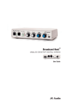
Warranty
Broadcast Host is covered by a 2-year warranty to be free
from defective workmanship and materials. In the event that
the Broadcast Host needs repair, you must call us to get an
authorization, and then carefully pack and ship it to us. You
will pay for shipping to us and we will pay for return back to
you, UPS ground. No free repairs will be made if the defect
was caused by misuse, weather conditions, or other cause,
except for defective workmanship or materials. THERE ARE
NO EXPRESSED OR IMPLIED WARRANTIES WHICH
EXTEND BEYOND THE WARRANTY HERE MADE.
Broadcast Host
Desktop Digital Hybrid
User Guide
02/07
JK Audio, Inc. 1311 E 6th Street, Sandwich, IL 60548
USA
Voice: (815) 786-2929
Toll Free: 800-JK-Audio
Fax: 815-786-8502
[email protected]
www.jkaudio.com
Copyright © 2007 JK Audio, Inc.
All Rights Reserved.
JK Audio
FCC Registration (continued)
Introduction
Broadcast Host will allow you to send and receive audio over
analog telephone lines. While this may seem like a simple
task that any telephone can do, the challenge is getting the
best quality audio from such a limited audio path.
What is a Digital Hybrid?
The Broadcast Host digital hybrid connects audio signals to a
standard analog telephone line without the variations in quality found with analog hybrids. The main function of a hybrid
is to bring in the caller’s voice from the phone line as clear
and clean as possible. In the real world, when you send your
voice down the telephone line it has a tendency to bleed over
into the caller’s audio. The hybrid must adapt to the phone
line in order to properly separate transmit and receive audio.
We use a 16 bit DSP (Digital Signal Processor) to continuously monitor the phone line and local audio signals to deliver
excellent trans-hybrid loss, also known as separation. Our
dual-convergence algorithm can achieve excellent separation, typically exceeding 50 dB.
Ready to go?
The Broadcast Host controls and connectors are clearly
marked and ready for operation. The Features diagrams and
Operation sections on the following pages will help you pinpoint any minor questions that you may have. If this is your
first exposure to a hybrid, we suggest that you read the entire
manual to allow you to take advantage of all these features.
Any Questions?
Before you pick up the phone... Please thumb through the
rest of this manual. You might find those deep technical
questions are covered on later pages.
2
b) The telephone equipment's FCC registration number. This
can be found on the bottom of your telephone equipment,
and,
c) The ringer equivalence number (REN) for this equipment.
The REN is used to determine the quantity of devices which
will be connected to the telephone line. Excessive RENs on
the telephone line may result in the devices not ringing in
response to an incoming call. In most, but not all areas, the
sum of the RENs should not exceed 5.0. To be certain of
the number of devices that may be connected to the line, as
determined by the total RENs, contact the local telephone
company.
3. Repair Instructions
If it is determined that your telephone equipment is
malfunctioning, the FCC requires that it not be used and that it
be unplugged from the modular outlet until the problem has
been corrected. Repairs to this telephone equipment can only
be made by the manufacturer or its authorized agents or by
others who may be authorized by the FCC.
For repair
procedures, follow the instructions outlined under the warranty
section of the manual.
4. Rights of the telephone company
If telephone equipment is causing harm to the network, the
telephone company may temporarily discontinue your
telephone service. If possible, they'll notify you before they
interrupt service. If advanced notice isn't practical, you'll be
notified as soon as possible. You'll be given the opportunity to
correct the problem, and you'll be informed of your right to file a
complaint with the FCC.
Your telephone company may make changes in its facilities,
equipment, operations or procedures that could affect the
proper functioning of your JK Audio product. If such changes
are planned, you'll be notified by your telephone company.
15
FCC Part 15 Compliance
Features
This equipment has been tested and found to comply with the
limits for a Class A digital device, pursuant to Part 15 of the FCC
Rules. These limits are designed to provide reasonable protection
against harmful interference when the equipment is operated in a
commercial environment. This equipment generates, uses, and
can radiate radio frequency energy and, if not installed and used in
accordance with the instruction manual, may cause harmful
interference to radio communications. Operation of this equipment
in a residential area is likely to cause harmful interference in which
case the user will be required to correct the interference at his own
expense.
Changes or modifications not expressly approved by JK Audio can
void the user's authority to operate the equipment.
FCC Registration
Your new JK Audio product has been registered with the Federal
Communications Commission (FCC). This product complies with
the standards in Part 68 of the FCC rules.
1. Connection and use with the nationwide telephone
network
The FCC requires that you connect this telephone equipment
to the national telephone network through a USOC RJ-11C
modular telephone jack.
This equipment may not be used with Party Line Service or
Coin Telephone Lines.
This equipment is hearing aid compatible.
2. Information for the telephone company
Upon request from your local telephone company, you are
required to provide the following information:
a) The "line" to which you will connect the telephone equipment
(that is, your telephone number), and
14
1
2
3
8
9
10
11
4
5
6
7
1.
Call Button - Press this button to answer an incoming call or to
connect your call through the hybrid if you have used an auxiliary phone to set up the call.
2.
Drop Button - Press this button to drop (hang up) a call
3.
Send 1 Level - Adjusts the signal level that you are sending
down the telephone line, through the female XLR input.
4.
Send 2 Level - Adjusts the signal level that you are sending
down the telephone line, through the 3.5mm mini jack input.
5.
Caller Level - Adjusts the level of the incoming caller’s audio
as it is going out the output jacks.
6.
Headphone Level - Adjusts the signal level coming from the
3.5mm front panel headphone jack.
7.
Headphones - The 3.5mm stereo headphone jack contains a
mix of both the Send input audio and the Caller audio.
8.
OH LED - Lit when you are on line with a call (Off-Hook).
9.
Send LEDs - Displays the signal level going to the phone line.
10. Power LED - Lit when unit is plugged in and receiving power.
11. Receive LEDs - Displays the signal level coming in from the
phone line, after the DSP. This signal level will not change
when you adjust the Caller knob.
3
Features (continued)
12
13
14
15
Specifications
16
17
18 19
20
21
Inputs:
Send 1:
Send 2:
12. Line Jack - Connect to a standard, single line, analog telephone line.
Outputs:
Balanced:
13. Phone Jack - Connect a single line analog telephone for call
setup, dialing, or call screening. (Optional)
14. Auto-Answer - this switch enables Broadcast Host to automatically answer an incoming call and then disconnect after
the caller hangs up. Auto answer will occur on the first ring.
15. Caller Output - Male balanced XLR output contains only the
caller’s voice.
16. Send 1 Input - Female balanced XLR input for signals going
out to the phone line. Mic or line level input.
Male XLR, 200 ohm, 500 mV RMS
(+4 dBv max)
Unbalanced:
3.5mm stereo, 50 ohm, 250 mV RMS
(0 dBv max)
Left = send, Right = caller
Headphone:
3.5mm stereo, 8 ohms, 250 mW
mixed send and receive
RJ11C
Phone Line:
RJ11C
Isolation:
1500 VAC
Ringer:
0.5B REN
18. Send 2 Mono Input - 3.5mm mono mini jack input for signals
going into the phone line. Line level.
20. Remote Control Jack - 8 pin modular RJ-45 jack for connection to the optional JK Audio Guest Module 1 Remote Keypad
or your broadcast console switch contacts. Do not connect this
jack to your computer network port.
3.5mm mono,20k ohm,
250 mV RMS (-10 dBv nom)
Phone Line:
Aux Phone:
17. Mic / Line switch - Sets the front end sensitivity of the Send 1
XLR jack. Set to Mic if you intend to connect a dynamic microphone directly to the Send 1 jack. Set to Line if you are connecting to the output of a mic mixer.
19. Stereo Output - 3.5 mm stereo mini jack output contains both
Send and Caller audio channels with levels determined by the
Send 1 and Send 2 level controls and the Caller level control.
Left channel contains your local Send audio and right channel
contains the Caller's audio from the telephone line.
Balanced Female XLR, 1k ohm,
-10 mV RMS (-35 dBv nom)
Mic/Line pad switch = +4 dBv max
Frequency Response: Telephone side 200 Hz - 3600 Hz
Power:
120-240 VAC power supply
(included)
Size:
7" x 6" x 1.6" (18 x 15 x 4.2 cm)
Weight:
2.2 pounds (1 kg)
21 Power Jack - For connection only to the supplied 9VDC regulated power supply.
4
13
Notes
Connection
Although each application may require a slightly different setup,
there are two primary configurations.
For a direct connection to Broadcast Host:
• Phone Line - Connect the supplied RJ-11 phone line cable between the jack marked "Line" and your wall jack. Be sure this
jack supports standard single line analog telephone operation.
• Send Audio - Connect a dynamic microphone cable to the Send
1 jack on the Broadcast Host. Be sure to set the Broadcast
Host Mic/Line switch to the “Mic” position.
• Output - Connect a stereo cable from the mini-jack “Stereo Out”
on the Broadcast Host to the “Line In” on your computer sound
card or other recording equipment that has a stereo input.
• Power - Connect the supplied DC power supply to the back of
the Broadcast Host and then to an AC power outlet.
• Your Broadcast Host is now ready to take calls. You may want
to connect an auxiliary telephone to the Broadcast Host “Phone”
jack so you can dial out and set up calls, or simply use the
“Auto-Answer” feature to answer incoming calls.
• Place a test call to a quiet location. Set the “Send” level control
so that while you are speaking into the microphone, the Send
LEDs on the hybrid light the -20 dB green LED consistently and
flash the -9 dB green LED. If you flash the -3 dB red LED, lower
the level. Set the “Caller” control for good recording level of the
caller audio at the output jack.
Computer
Set to
“Mic”
Sound Card
Line Line Mic
in
out in
12
5
Connection (continued)
FAQs
To Connect Broadcast Host through a mixer—Mix Minus Setup
?
!
Does Broadcast Host work with Vonage IP telephony?
Yes, however customers have reported one glitch in the Vonage
system. If the Broadcast Host is set to auto-answer or if the call
is manually answered on the first ring there will be a considerable amount of noise on the call. This can be avoided by initiating the call from your location or manually answering after the
second ring. If auto-answer is an integral part of your application
you may contact Vonage directly to downgrade to a previous
version of their firmware. This information is valid as of January
23, 2006. We have no direct connection with Vonage and therefore will not know when this particular problem is resolved.
?
There is a loud hum on the output of my Broadcast Host,
even when nothing else is connected. What else could it
be?
Make certain you are using the regulated power supply that was
shipped with this unit. Power supplies are not all the same.
Auxiliary telephone optional.
Used to dial out to set up calls.
Connect Aux (or FX) Send on
mixer to Send 1 on Broadcast
Host, Mic/Line button out (Line)
Connect Caller to any
line level input on mixer
Number of microphones
depends on mixer
!
?
Use Main Outputs,
USB or Firewire
connectors to
send audio to
recording device,
or broadcasting
equipment inputs
!
?
!
For whichever input channel you have the Caller connected to, turn the
corresponding Aux control to minimum (usually hard left). All other Aux
controls should be set for what you want to send to the phone line. Each
Aux Send bus is completely separate from all other outputs, so these Aux
controls will not affect what is heard on the Main outputs or on any other
Aux buses. This Aux Send bus should be pre-fader, so you can use the
fader controls to set the levels of each channel to the main output.
6
I need to be able to use my Broadcast Host at an office
building but they only have a multi-line PBX phone system.
Is there some way I can still connect this device?
Talk to their phone specialist and ask for a standard analog line.
Any line that can be used for a fax machine or modem should
work fine. The auto answer or auto disconnect features may not
work the same however. That depends on how the PBX system
is configured. If this is where you will typically be working with
the hybrid, you might consider our innkeeper PBX instead.
Can I still use my phone to take regular calls or do I have to
disconnect the Broadcast Host when I am not using it?
You can leave the Broadcast Host in place and your telephone
will continue to operate normally. Audio will only pass through
the hybrid when you press the “Call” button.
11
FAQs
Operation
?
• Using balanced XLR cables (not included) with 1/4” TRS adapt-
!
?
!
?
!
?
!
?
!
Will the digital hybrid provide phantom power for a condenser mic?
No, this device will not provide phantom power. If you connect a
microphone directly to the Broadcast Host, you should use a
dynamic mic.
What happens if someone takes a second phone off-hook
when the Broadcast Host is on a call?
Broadcast Host will treat the other local voice the same as the
caller. It will attempt to keep transmit audio from returning back
with the caller's audio, but this becomes more difficult with this
scenario. The local voice will certainly sound much louder than
the distant caller's voice.
Why is there a Send 2 mini-jack on the back of my Broadcast Host?
This is a second line level input to the Broadcast Host. Here you
can connect another device, such as a CD player, the Line Out
from your computer or even the output of your personal audio
player, to add audio to the conversation. This enables you to
play background music or other sound bites during your discussion. Do not connect a microphone to this jack. This is a mono
input. If you connect a stereo output here, such as a computer
line out, you will only receive Left channel audio.
How do I record onto my computer and edit the files?
You will need to purchase or download any audio editing software of your choice. You may also need to edit the audio configuration files on your computer or in your software to allow recording in stereo. Broadcast Host just enables you to access the
audio from your phone line.
Why does my laptop only record half of the conversation?
I’m using the Stereo output on the Broadcast Host and I
have a stereo cable.
Most laptop computers only have a mic input, which is mono.
You will need to either get a sound card with a stereo line level
input for your laptop or use a USB or FireWire interface product.
10
ers if necessary for your mixer, make all connections as shown.
• On your mixer and on Broadcast Host, set all controls to nominal
levels, usually 12:00.
• On your mixer, set local microphone channel input gain for good
microphone level.
• On your mixer, set all output faders and the main mix control for
good recording level of the local audio.
• On your mixer, set the headphone level for comfortable listening.
• On your mixer, set the Caller channel input gain to line level, if
there is a selector switch. If there is no line level input and you
must connect the Caller to a Mic in, turn the input gain way down.
• On your mixer, set the Aux control for Caller channel only to mini-
mum (zero or ∞). Aux controls for all other channels should initially be set at 12:00. Set Aux Send Master for good overall level.
• Place a test call. On your mixer, set the Aux Send controls
(individual Aux Send controls for Microphone channels as well as
Master Aux Send control) so that while you are speaking into the
microphone the Send LEDs on the hybrid light the -20 dB green
LED consistently and flash the -9 dB green LED. If you flash the
-3 dB red LED, lower the level.
• On your mixer, set the Caller channel output level for good re-
cording level of the caller audio. If you need more control of this
level, on the mixer first adjust the caller channel input gain (if applicable), then adjust Caller control on the Broadcast Host.
Mix-Minus Setup
A mix-minus signal is an audio signal that contains a mix of your
local microphones plus any other audio, minus the Caller's own
voice. Sending the Caller’s audio back to the Broadcast Host
through Send 1 will cause an echo, or feedback.
If your mixer does not have an Aux Send bus, you can achieve the
same results using Pan controls with the Left and Right outputs.
Simply pan all the microphones, etc. to the Left output and pan the
Caller to the Right output. Then connect only the Left output to the
Broadcast Host Send 1. Or, you may use an external Mix-Minus
box that will create this signal for you.
7
Operation (continued)
Operation (continued)
Send Signal Level
The Send LEDs display the signal level as it goes out over the
phone line. The goal is to drive the phone line audio at high
enough levels to avoid phone line noise, but not so loud as to
cause excessive clipping. Adjust the Send level control so that you
rarely see flashes of the red -3dB peak Send LED. These flashes
should occur only during loud speech bursts. If the red LED stays
lit for extended periods you can assume that much of your speech
is being clipped or distorted. In this case you should lower the
Send volume control for the input that is causing the clipping.
Auto-Answer
The Auto-Answer feature will answer on the first ring. When AutoAnswer is enabled, you can still make calls manually using the Call
button. When finished, you can either drop the call manually or allow the call to Auto-Disconnect. Broadcast Host will look for a CPC
disconnect signal from the phone company to determine when a
call has disconnected. This can take up to a minute.
Caller Signal Level
The Receive LEDs display the strength of the audio signal coming
from the phone line just after the DSP. The Caller level control
knob does not change what you see on these LEDs. Adjust the
Caller level control to give you the best signal level at the Caller
XLR output or the Caller channel of the stereo output mini jack.
Optional Jumper Settings
If the incoming Caller level is too high and peaking the red -3 dB
LED, you may need to change the setting of an internal jumper.
Disconnect power from the hybrid and remove the cover of the
Broadcast Host to locate Jumper 1. The default position for this
jumper is closed (covering both pins). Changing the jumper to the
open position (either remove the jumper or cover just one pin) will
provide 6 dB attenuation of the incoming audio signal.
Remote Control Jack
The RJ-45 jack on the back of the Broadcast Host provides connection to an optional JK Audio Guest Module 1* remote control, or
it can be wired to the switch contacts on your broadcast console.
Do not connect this jack to the network port on your computer.
RJ-45 Pinout:
Pin 1:
Pin 2:
Pin 3:
Pin 4:
Pin 5:
Pin 6:
Pin 7:
Pin 8:
Ground
Call / Drop Control (main control pin)
Ring / OH LED
DTMF Input
+4.3 VDC
Reserved
Reserved
Reserved
Momentarily connect pin 2 to pin 5 (power) through a 100 ohm 1/4
watt resistor to take Broadcast Host off-hook.
Auxiliary Telephone
An auxiliary telephone provides you with an easy way to dial out or
set up your calls. Broadcast Host will disconnect the auxiliary telephone when you press the Call button. If you need to take the call
back on the aux telephone, simply pick up the telephone handset
before the Broadcast Host’s Drop button is pressed.
Momentarily connect pin 2 to pin 1 (ground) through a 100 ohm
1/4watt resistor to release (Drop) the phone line.
To use an auxiliary phone equipped with a “Hold” feature to place
or screen a call, first set up the call and place the call on hold.
When you are ready to take the call on Broadcast Host, press the
Call button and your telephone will automatically release the hold.
Pin 5 supply output is current limited to 100 mA with a resettable
fuse for use with the Guest Module and pin 2 connections. Do not
attempt to power additional circuitry from this pin.
Your phone will operate as a normal telephone anytime you are in
Drop mode. Leaving the hybrid connected between the wall jack
and your telephone will not affect normal use of your phone. Audio
will only pass through the hybrid when you press the Call button.
* Contact your JK Audio dealer for additional information. Guest
Module 1 remote keypad not available for sale in Europe, Australia
or New Zealand.
8
Pin 3 contains a 4.3 VDC, 40 mA current limited output to drive a
signal LED. We suggest adding a 200 ohm 1/4w resistor in series
with an LED connected to ground.
9