1
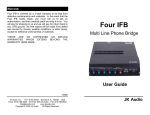
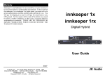
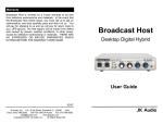
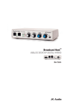
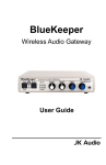
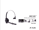
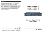
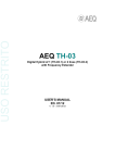
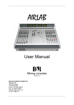
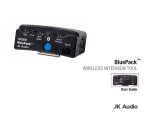
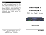
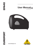
innkeeper LTD
Digital Hybrid
User Guide
JK Audio
Introduction
Innkeeper LTD allows you to send line level signals into the phone
line while maintaining excellent separation between your voice and
the caller. The balanced XLR output jack contains only the caller’s
voice, making this the perfect companion to mixers, consoles, and
PA systems that demand talk show quality audio from a phone line.
The digital hybrid connects audio signals to a standard analog
phone line without the transmit/receive crosstalk common to analog
hybrids. Its Digital Signal Processor (DSP) continuously monitors
both the phone line and audio signals to deliver excellent separation. This proprietary, dual-convergence echo canceller algorithm
can achieve separation typically exceeding 50 dB without any setup
and without sending a noise burst down the line. While this may
sound complicated, it’s all done automatically during every call.
Ready to go?
The innkeeper LTD controls and connectors are clearly marked and
ready for operation. The Features, Setup diagrams and Operation
sections on the following pages will help you answer any minor
questions that you may have. If this is your first exposure to a
hybrid, we suggest that you read the entire manual to allow you to
take advantage of all these features.
Any Questions?
Before you pick up the phone... Please thumb through the rest of
this manual. You might find those deep technical questions are
covered on later pages.
2
Table of Contents
Introduction . . . . . . . . . . . . . . . . . . . . . . . . . . . . . . . . . . . . . . .
2
Warnings and Safety Precautions . . . . . . . . . . . . . . . . . . . . . . 4
Features
Front View . . . . . . . . . . . . . . . . . . . . . . . . . . . . . . . . . . 5
Rear View . . . . . . . . . . . . . . . . . . . . . . . . . . . . . . . . . . 6
Connecting Cables . . . . . . . . . . . . . . . . . . . . . . . . . . . . . . . . . 7
Setup diagrams
Studio Mix-Minus Setup . . . . . . . . . . . . . . . . . . . . . . . 8-9
Mix-Minus Explanation . . . . . . . . . . . . . . . . . . . . . . . . . 10
Simple Mix-Minus Setup . . . . . . . . . . . . . . . . . . . . . . . 11
PA System Setup . . . . . . . . . . . . . . . . . . . . . . . . . . . . . 12
Alternative to Mix-Minus Setup . . . . . . . . . . . . . . . . . . 12
Operation
Auxiliary Telephone . . . . . . . . . . . . . . . . . . . . . . . . . . . 13
Optional Jumper Settings . . . . . . . . . . . . . . . . . . . . . . 13
Auto Answer . . . . . . . . . . . . . . . . . . . . . . . . . . . . . . . . 13
Remote Control Jack . . . . . . . . . . . . . . . . . . . . . . . . . . 14
Optional Guest Module 1 . . . . . . . . . . . . . . . . . . . . . . . 14
FAQs . . . . . . . . . . . . . . . . . . . . . . . . . . . . . . . . . . . . . . . . . . . . 15
Specifications . . . . . . . . . . . . . . . . . . . . . . . . . . . . . . . . . . . . . 16
Block Diagram . . . . . . . . . . . . . . . . . . . . . . . . . . . . . . . . . . . . . 17
FCC Compliance and Registration . . . . . . . . . . . . . . . . . . . . . 18-19
Warranty . . . . . . . . . . . . . . . . . . . . . . . . . . . . . . . . . . . . . . . . . 20
3
Warnings and Safety Precautions
1.
Read and keep these instructions.
2.
Heed all warnings.
3.
Follow all instructions.
4.
Clean only with a soft dry cloth.
5.
Do not install near any heat sources such as radiators, heat
registers, stoves, or other apparatus (including amplifiers) that
produce heat.
6.
Do not defeat the safety purpose of the three-prong groundingtype plug. If the provided plug does not fit into your outlet, consult an electrician for replacement of the obsolete outlet.
7.
Do not use this unit if the electrical power cord is frayed or broken. The power cord should be routed so that it is not likely to
be walked on or pinched by items placed upon or against it.
8.
To reduce the risk of fire or electric shock, do not expose this
apparatus to rain or moisture.
9.
Refer all servicing to qualified service personnel.
10. The following warning symbol may be used elsewhere in this
manual:
The exclamation point within an equilateral triangle is
intended to alert the user of the presence of important
operating and maintenance (servicing) instructions in
the user guide.
4
Features—Front View
1
2
3
5
4
6
7
8
Figure 1: Front View
1.
Call Button - Takes the phone line off hook - press this button
to answer a call or to direct a call from your phone through the
hybrid.
2.
OH LED - Lit when you are on line with a call (off-hook). LED
will flicker when you have an incoming call.
3.
Drop Button - Press this button to drop (hang up) a call.
4.
Send LEDs - Indicate the signal level going out to the phone
line.
5.
Power LED - Indicates that the unit is receiving power.
6.
Caller LEDs - Indicate the signal level coming in from the
phone line, after the DSP.
7.
Send Level - Recessed volume control adjusts the signal that
you are sending down the telephone line.
8.
Caller Level - Recessed volume control adjusts the level of the
signal coming in from the telephone line, going out the “Caller”
XLR jack.
5
Features—Rear View
9
10
11
12
13
14
15
Figure 2: Back View
9.
Phone Line - Connect only to a standard, single line, analog
telephone line.
10. Aux. Phone - Connect a single line analog telephone for call
setup / dialing, or producer call screening.
11. Auto Answer - This button enables innkeeper LTD to automatically answer an incoming call and then disconnect after the
caller hangs up. Auto Answer will occur on the first ring.
12. Caller Output - Male balanced XLR line level output contains
only the caller’s voice.
13. Send Input - Female balanced XLR line level input for signals
going out to the phone line.
14. Remote Control Jack - 8-pin modular RJ-45 jack for connection to the optional JK Audio Guest Module 1 Remote Keypad
or your broadcast console switch contacts. Do not connect this
jack to your computer network port.
15. Power - For connection only to the supplied 9VDC regulated
power supply.
6
Connection
Connecting Cables
Although each application will require a slightly different setup, there
are some cables that everyone can agree upon:
1. Phone Line - Connect the supplied RJ-11 phone line cable
between the jack marked “Line” and your wall jack. Be sure this
jack can support standard single-line analog telephone
operation.
2. Send Audio - Connect a line level audio signal from the output of
your other equipment such as a mixing console or PA system, to
the XLR Send jack on the innkeeper LTD.
3. Caller Audio - Connect the Caller output jack to a line level input
on your mixing console or other equipment.
4. Power - Connect the supplied AC power cord to the back of the
innkeeper LTD and then to an AC power outlet.
This device should be connected to an adequate surge
protective device at all times both for the power connector
and for the telephone line to avoid damage from lightning
or electrical surges.
Your innkeeper LTD is now ready to take calls. You may want to
connect an auxiliary phone to the innkeeper for call setup, or you
can simply use Auto-Answer or the Call button to answer an
incoming call.
7
Studio Mix-Minus Setup
Auxiliary telephone optional.
Used to dial out to set up calls.
Caller to line level
input on mixer
Aux Send B (post-fader) on
mixer to Send on hybrid
Number of mics
depends on mixer
Use Main Outputs,
USB or Firewire
connectors to
send audio to
recording device
or broadcasting
equipment inputs
Figure 3: Studio Mix-Minus Setup
8
Studio Mix-Minus Setup
Following the instructions in the owner’s manual for your audio
mixer, connect your microphones, headphones and recording device and set the levels on your mixer.
On the front of the innkeeper LTD, set the Send and Caller volume
controls to center.
To connect the innkeeper LTD to your mixer, use a balanced female
XLR cable with an adapter if necessary (not included) to connect
the Caller jack on the back of the innkeeper LTD to any unused Line
input on the mixer. Using a balanced XLR male to 1/4” cable (not
included), connect the Post-Fader Aux bus output (Aux Send B on
this mixer diagram) to the Send XLR input on the innkeeper LTD.
On your mixer, locate the row of Aux B knobs. This row of knobs will
set the level of each input channel to the Aux B output which is sent
to the phone caller. Turn all of these knobs to 9 o’clock except for
the channel you have the Caller from the innkeeper LTD connected
to (Channel 4 in this example). This Aux B knob should be set fully
off (hard left on most mixers).
Speak into your microphone and watch the level indicators on the
mixer. Adjust your Mic Level so your audio is at 0 dB on the meter
most of the time and occasionally up to +3 dB. Repeat for each mic.
Next check the Send level meter on the front of the innkeeper LTD.
Adjust the Send volume control on the innkeeper LTD so that both
green lights are on while you speak, and you only occasionally see
the red light. Some mixers may have an Aux Send master control
that will affect the audio level you send to the innkeeper LTD. You
should start with this knob at 12 o’clock and adjust it if necessary to
get the correct level on the innkeeper LTD.
Next set up a call on your phone line. Press the Call button on the
front of the innkeeper LTD. As the Caller speaks, adjust the Gain
knob on the mixer for the channel you have the Caller audio connected to (Channel 4 on this diagram) until the Peak light for that
channel comes on, then reduce the level slightly just until the light
goes out.
Now you are ready to go. These settings should work for most
phone calls.
9
Mix-Minus Explanations
Why do I need a Mix-Minus Setup?
Mix-minus is an audio signal that is designed to avoid feedback and
echo in a conference or telephone interface application. When connecting a phone hybrid to a mixing console, the caller’s audio will be connected to an input channel on the mixer along with all the microphones,
music, etc. All of these inputs combine to create the Master mix to be
sent to your broadcast, recording device, or the speakers of your PA
system. However, if you connect this Master mix to the input of the hybrid, you are also sending the caller’s own audio back to the caller.
This completes a feedback loop and creates a strange and annoying
echo. That is why it is important to create a special mix that contains a
mix of all the microphones, music, etc., “Minus” the caller’s audio.
Wireless Phone Interface
Mix Minus Caller
Mix Plus Caller
Audio Mixer
PA System,
Broadcast,
Podcast, etc.
Which Mix-Minus Setup Should I Use?
Most radio stations and recording studios should use the Studio Setup
shown on pages 8-9. Using an Aux Send output that is Post Fader will
keep the audio that is being sent out to the caller tied to the same output you send to your broadcast or PA system. This way your sound
engineer can more easily control each channel. During a station break,
the talent microphones can be muted simply by turning off the output
level knob or slider and their audio will not be sent to the broadcast or
to the caller.
If you have a small studio and you use your wireless phone hybrid to
record interviews, you might consider using the Simple Setup on page
11. When the Aux Send output is Pre Fader, the levels you set on the
Aux Send controls will only affect what the Caller hears, and the levels
you set at the output faders will only affect the recording or broadcast.
If the talent wants to be able to talk to the caller during station breaks,
this is the setup you should use, although the talent would need to connect their headphones to the hybrid instead of to the mixer. You should
also use this setup if you want to be able to send music or sound effects to the broadcast that the caller will not hear.
10
Connection
Simple
Setup
- Alternate
for Mixer Setup Diagrams
Auxiliary telephone optional.
Used to dial out to set up calls.
Caller to any line
level input on mixer
Aux Send A (pre-fader) on
mixer to Send on hybrid
Number of mics
depends on mixer
Use Main Outputs,
USB or Firewire
connectors to
send audio to
recording device
For whichever input channel you have the Caller connected to, turn the
corresponding Aux A control to minimum (usually hard left). All other Aux
A controls should be set for what you want to send to the phone line.
Each Aux Send bus is completely separate from all other outputs, so
these Aux controls will not affect what is heard on the Main outputs or on
any other Aux buses. This Aux Send bus should be pre-fader if possible
so you can use the Level controls (faders) to set each channel at the
main recording output without changing the levels you send to the caller.
Figure 4: Simple Setup for Mixer
11
PA System Setup
Auxiliary telephone optional.
Used to dial out to set up calls.
Speakers
Inputs
PA System
Console
Outputs
Figure 5: PA System Setup
Alternative to Mix-Minus Setup
If your mixer does not have an Aux Send bus, you can achieve the
same results using Pan controls with the Left and Right outputs.
Simply pan the Caller to the Right output. Then connect only the
Left output to the innkeeper LTD Send XLR. This signal should contain all inputs except the Caller. Or, you may use an external MixMinus device that will create this signal for you.
12
Connection - Alternate Setup Diagrams
Operation
Auxiliary Telephone
An auxiliary telephone provides you with an easy way to dial out or
set up your calls. Innkeeper LTD will disconnect the auxiliary telephone when you press the Call button. If you need to take the call
back on the aux telephone, simply pick up the telephone handset
before the innkeeper LTD’s Drop button is pressed.
To use an auxiliary phone equipped with a “Hold” feature to place or
screen a call, first set up the call and place the call on hold. When
you are ready to take the call on innkeeper LTD, press the Call button and your telephone will automatically release the hold.
Your phone will operate as a normal telephone anytime you are in
Drop mode. Leaving the hybrid connected between the wall jack
and your telephone will not affect normal use of your phone. Audio
will only pass through the hybrid when you press the Call button.
Optional Jumper Settings
If the incoming Caller level is too high and peaking the red -3 dB
LED, you may need to change the setting of an internal jumper. Disconnect power from the hybrid and remove the cover of the innkeeper LTD to locate Jumper 1. This blue jumper should be close to
the center of the circuit board with a label printed on the board. The
default position for this jumper is closed (covering both pins).
Changing the jumper to the open position (either remove the jumper
or cover just one pin) will provide 6 dB attenuation of the incoming
audio signal.
Auto-Answer
The Auto-Answer feature will answer on the first ring. When AutoAnswer is enabled, you can still make calls manually using the Call
button. When finished, you can either drop the call manually or allow the call to Auto-Disconnect. Innkeeper LTD will look for a CPC
disconnect signal from the phone company to determine when a call
has disconnected. This can take up to a minute.
13
Operation
Remote Control Jack
The RJ-45 jack on the back of the innkeeper LTD provides connection to a JK Audio Guest Module 1* remote control device, or it can
be wired to the switch contacts on your broadcast console. Do not
connect this jack to the network port on your computer.
RJ-45 Pinout:
Pin 1:
Pin 2:
Pin 3:
Pin 4:
Pin 5:
Pin 6:
Pin 7:
Pin 8:
Ground
Call / Drop Control (main control pin)
Ring / OH LED
DTMF Input
+4.3 VDC
Reserved
Reserved
Reserved
Momentarily connect pin 2 to pin 5 (power) through a 100 ohm 1/4
watt resistor to take innkeeper LTD off-hook.
Momentarily connect pin 2 to pin 1 (ground) through a 100 ohm 1/4
watt resistor to release (Drop) the phone line.
Pin 3 contains a 4.3 VDC, 40 mA current limited output to drive a
signal LED. We suggest adding a 200 ohm 1/4w resistor in series
with an LED connected to ground.
Pin 5 supply output is current limited to 100 mA with a resettable
fuse for use with the Guest Module and pin 2 connections. Do not
attempt to power additional circuitry from this pin.
Guest Module 1*
This convenient device gives you remote access to the on-hook /
off-hook and dial features of the innkeeper LTD. The Call button will
flicker when a call comes in and stay lit while a call is present.
When you dial out using the Guest Module 1 keypad, tones are sent
directly down the phone line, and do not come back mixed with the
Caller audio. This device can be used to send DTMF tones to digital
phone services such as a conference bridge without the tones being
recorded.
* Contact your JK Audio dealer for more information on this optional
accessory.
14
FAQs
?
!
Does the innkeeper LTD send a burst or beep down the phone
line at the beginning of each call like our current hybrid?
No, innkeeper LTD uses the actual transmit signal to evaluate the
phone line and tune its algorithm. As you begin to speak, innkeeper
LTD is hard at work canceling your voice from the Caller Output jack.
Within milliseconds your voice is reduced into the noise floor.
?
!
Can I use the innkeeper LTD on a VoIP line?
?
The caller’s audio is too high and is always distorted even
though I have the Caller level control turned down low. What
else can I do?
The Receive LED meter will indicate the level of audio coming in from
the telephone line, just after it passes through the DSP. The Caller
level control will only set how much of that audio will be sent to the
output jack, and will have no effect on the LED meter. If your incoming audio level is unusually hot and already peaking the –3 dB LED,
there is a jumper on the circuit board you can change to attenuate
the incoming audio. Please see page 13 for more information.
!
?
!
?
!
Many VoIP lines have an analog telephone adapter you can connect
your telephone to. If you can use any standard analog telephone,
then innkeeper LTD should work great. If you have to use a specific
telephone, you should consider our PBXport digital hybrid instead.
I have my new innkeeper LTD connected to the phone jack in
my office. Why does it keep dropping the calls as soon as I try
to connect it?
The telephone jack in your office is very likely for a multi-line phone
system. The jack may look like a standard phone jack, but it is wired
differently and may carry voltage on different pins which could cause
serious damage to your hybrid. Innkeeper LTD should only be connected to a single, analog phone line. Check with the telephone specialist in your building for the possibility of getting an analog line for
your innkeeper LTD.
My innkeeper LTD is connected to an analog line at my office
location, and will auto-answer an incoming call. Why won’t it
auto-disconnect at the end of the call?
A PBX phone system can be programmed to provide an analog
line. Check with the telephone specialist in your building for the
possibility of resetting the characteristics of your analog line to provide an appropriate CPC disconnect signal.
15
Specifications
Input
Send:
Output
Caller:
Balanced Female XLR, 20k ohms,
500 mV RMS (-4 dBu nom.)
Balanced Male XLR, 200 ohms,
500 mV RMS, -4 dBu nom, +14 dBu Max.
Remote Jack:
RJ-45
Phone Line Jack:
RJ-11C
Isolation:
1500 VAC
Ringer:
0.8B REN
Frequency Response:
Telephone side 200 Hz - 3600 Hz
Power:
120-240 VAC power supply (included)
Size:
7.6" x 5.3" x 1.5" (20 x 14 x 4 cm)
Weight:
2.7 pounds (1.2 kg)
16
Block
Operation
Diagram
(continued)
Figure 6: Block Diagram
17
FCC Part 15 Compliance
This equipment has been tested and found to comply with the limits
for a Class A digital device, pursuant to Part 15 of the FCC Rules.
These limits are designed to provide reasonable protection against
harmful interference when the equipment is operated in a
commercial environment. This equipment generates, uses, and can
radiate radio frequency energy and, if not installed and used in
accordance with the instruction manual, may cause harmful
interference to radio communications. Operation of this equipment
in a residential area is likely to cause harmful interference in which
case the user will be required to correct the interference at his own
expense.
Changes or modifications not expressly approved by JK Audio can
void the user's authority to operate the equipment.
FCC Registration
Your new JK Audio product has been registered with the Federal
Communications Commission (FCC). This product complies with
the standards in Part 68 of the FCC rules.
1. Connection and use with the nationwide telephone network
The FCC requires that you connect this telephone equipment to
the national telephone network through a USOC RJ-11C
modular telephone jack.
This equipment may not be used with Party Line Service or
Coin Telephone Lines.
This equipment is hearing aid compatible.
2. Information for the telephone company
Upon request from your local telephone company, you are
required to provide the following information:
a) The "line" to which you will connect the telephone
equipment (that is, your telephone number), and
18
FCC Registration (continued)
b) The telephone equipment's FCC registration number. This
can be found on the bottom of your telephone equipment,
and,
c) The ringer equivalence number (REN) for this equipment.
The REN is used to determine the quantity of devices which will
be connected to the telephone line. Excessive RENs on the
telephone line may result in the devices not ringing in response
to an incoming call. In most, but not all areas, the sum of the
RENs should not exceed 5.0. To be certain of the number of
devices that may be connected to the line, as determined by the
total RENs, contact the local telephone company.
3. Repair Instructions
If it is determined that your telephone equipment is
malfunctioning, the FCC requires that it not be used and that it
be unplugged from the modular outlet until the problem has
been corrected. Repairs to this telephone equipment can only
be made by the manufacturer or its authorized agents or by
others who may be authorized by the FCC.
For repair
procedures, follow the instructions outlined under the warranty
section of the manual.
4. Rights of the telephone company
If telephone equipment is causing harm to the network, the
telephone company may temporarily discontinue your telephone
service. If possible, they'll notify you before they interrupt
service. If advanced notice isn't practical, you'll be notified as
soon as possible. You'll be given the opportunity to correct the
problem, and you'll be informed of your right to file a complaint
with the FCC.
Your telephone company may make changes in its facilities,
equipment, operations or procedures that could affect the
proper functioning of your JK Audio product. If such changes
are planned, you'll be notified by your telephone company.
19
Warranty
Innkeeper LTD is covered by a 2-year warranty to be free
from defective workmanship and materials. In the event that
the innkeeper LTD needs repair, you must call us to get an
authorization, and then carefully pack and ship it to us. You
will pay for shipping to us and we will pay for return back to
you, UPS ground. No free repairs will be made if the defect
was caused by misuse, weather conditions, or other cause,
except for defective workmanship or materials.
THERE ARE NO EXPRESSED OR IMPLIED WARRANTIES
WHICH EXTEND BEYOND THE WARRANTY HERE MADE.
06/09
JK Audio, Inc. 1311 E 6th Street, Sandwich, IL 60548
USA
Voice: (815) 786-2929
Toll Free: 800-JK-Audio
Fax: 815-786-8502
[email protected]
www.jkaudio.com
Copyright © 2009 JK Audio. All rights reserved.