1
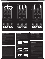
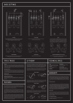
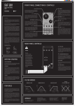
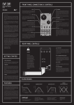
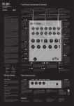
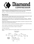
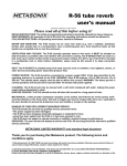
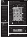
FT 201
FRONT PANEL CONNECTIONS & CONTROLS
ANALOG FILTER/1O STEP
SEQUENCER
_
USER MANUAL
The patch bay consists of ten 1/4” mono jack sockets used to send and receive various audio or control voltage signals. Blank arrows mark CV inputs/outputs, black arrows mark audio inputs/outputs.
If the arrow is pointing towards the jack socket it shows you that this is an output. If the arrow is pointing away from the jack socket it is an input.
The FT201 has been designed to accept unipolar CV signals only. Because the pedal runs on 9 V, every time you patch a control voltage to one of the CV inputs, the respective knob (e.g. SPEED knob or
SPEED IN (CV input) determines the offset voltage of your CV input signal.
(Audio Output) BAND PASS
1
The bandpass output of the filter.
(CV Input) CUTOFF
(Audio Output) LO PASS
6
The lowpass output of the filter.
7
SEQUENCER OUT (CV Output)
The output of the sequencer, ranging from 0 –
7V. Note that this is the sum of the sequencer
itself and the the CUTOFF knob.
2
Dear KOMA user,
Filters are amongst the most important audio sculpting tools
when it comes to defining your own unique sound. There’s a lot
of discussion going on about different filter topologies, their respective sound and how to electronically solve these different
approaches. At KOMA Elektronik, we went for a very versatile filter
architecture called state variable filter. One of the advantages
of this filter is that you have band pass, high pass and lowpass
characteristics available simultaneously for a given input. Other
musically convenient advantages are the independently adjustable Q (resonance) and gain that can be set without affecting
other variables.
There are two gain cells in the signal path of a voltage-controlled
state variable filter so there are different approaches to represent those gain cells. Usually these gain cells are represented by
an IC called ‘transconductance amplifier’ (a small chip) but for the
FT201 we decided to take another electronic part here commonly
known as ‘vactrols’.
What is a vactrol? Basically it’s a light dependent resistor (LDR)
and a LED kissing each other under a lightproof plastic blanket.
When you send current through the LED, it shines brighter, therefore the resistance of the LDR decreases and vice versa. Vactrols
are great for sound application because they are not prone to
distortion and are known for their soft and organic, analog response and sound.
Sequencers, on the other side, are great tools for modulation,
possibly the most logical thing after a simple knob. With the onboard step-sequencer you can twiddle with charming frequencies and their resonant overtones or find a pretty pattern to go
through your tone. With the sequencer output on the patch bay
you can control other features of the pedal as well as other KOMA
Elektronik pedals or synthesizers that accept control voltage.
Combining these two sound tools brings up a whole new variety
of defining your sound and playfully work with it. Have fun with
your new machine!
All the best from Berlin,
The KOMA Elektronik Team
Wouter Jaspers
Christian Zollner
Controls the cutoff frequency
of the filter. When you insert a
control voltage into this input
the CUTOFF knob determines the
offset voltage.
(Audio Output) HI PASS
4
10
5
H
A
G
Hayden Moskowitz
GETTING STARTED
resonance
B
The INPUT GAIN slider of the FT201
provides you with an adjustable
gain to boost low level input signals. By sliding from left to right
you can boost your signal from
zero gain to 100 gain (0 to +20dB).
Footswitch
Cutoff
Sets the cutoff frequency for the
filter, simultaneously for all three
filter characteristics. Fully counterclockwise sets the cutoff frequency
to the lowest and fully clockwise to
the highest frequency.
F
Robert Kunz
SEQUENCER speed
The SEQ. SPEED knob sets the
speed of the sequencer: the time
it takes to go from one step to the
next one and at the same time
also the duration of each single
step (On the scale that means: 2
is the fastest, 10 is the slowest). If
you turn the SEQ. SPEED knob fully
counter-clockwise you can turn
the sequencer off with a ‘click’
(there’s a built-in switch in the
potentiometer).
The sequencer of the FT201 consists out of 10 steps that you set
with the 10 small knobs in the
middle of the unit. It is easy to
imagine these ten knobs as duplicates of the big CUTOFF knob,
the amount set with the little sequencer knob of the active step is
added to the current setting of the
CUTOFF knob, or in other words:
You can shift the sequencer CV up
and down with the CUTOFF knob,
similar to setting a bias voltage
for incoming CV signals. You can
use the sequencer CV Output on
the patchbay to controls another
function on the FT201 with CV or
send it to another device.
InpuT GaiN
SENSOR (CVOutput)
This is the CV output of the
infrared motion sensor. The closer
you move something towards the
sensor, the higher the CV raises.
You can set the sensitivity of the
sensor with a small trimmer on the
back called ‘Sensor’. The sensor
output is 0 – 8V.
Controls the amount of resonance
in your given filter setting. When
you insert a control voltage into
this input the RESONANCE slider
determines the offset voltage.
Sequencer Steps
AUDIO IN (Audio Input)
The main audio input of the FT201.
The sound source plugged in here
will go through the whole effects
section.
3
Accepts clock signals for the sequencer by overriding the internal clock set by the SPEED knob.
It reacts to rising edge triggers,
proceeding one step whenever a
trigger or gate signal arrives.
(CV Input) RESONANCE
SEQ. RESET (CV Input)
A rising edge trigger or gate signal arriving at this CV input resets
the sequencer to step 1. A trigger
will reset, and a gate will hold the
sequencer at step 1 as long as it
is high.
9
The highpass output of the filter.
(CV Input) EXT. CLOCK
8
C
Heavy duty Alpha foot switch
turning the effect on and off.
Seq. Length
D
The SEQ. LENGTH knob is a rotary switch that lets you
choose the length of the sequencer pattern from 2 –
10; in other words, on what step that the sequencer
will go back to step 1. The currently active step is indicated by a small red LED next to the step number.
E
Sensor
Emits a CV signal that can be connected to any
CV input on KOMA products or for example your
(modular) synthesizer or other effect unit. By
moving your hand over the sensor you can control the parameters of the CV input patched to it.
Sets the Q of the filter, better
known as resonance. The resonance of a filter determines the
gain increase of the signal at the
cutoff frequency. Set it to LOW
(left) to leave the signal gain at
cutoff frequency at zero and slide
it to HIGH (right) to hear plenty of
resonance at the given cutoff frequency. Be aware of the fact that
the filter might start self-oscillating when you are at or near maximum resonance.
1. Unpack your machine
The package comes with the FT201 pedal, a 9VDC, 500mA,
center-negative power supply and this manual. Make sure that
the power supply is rated for the line voltage of your country: 120
VAC for the USA, 220 VAC for Europe or most other countries.
2. Connect it
Be sure your amp or mixer is turned off, then connect your instrument to the FT201 by using the AUDIO INPUT on the upper right
of the patch bay. Connect one of the three filter outputs to your
amp or mixer.
REAR PANEL CONTROLS
The FT201 is running on a +9V power supply. To make the unit compatible to all other equipment out there, we provide you with a trimmer for each CV input on the backside of the panel. So whenever
you notice a significant distortion or clipping in your control signal waveform or strange CV behavior simply turn the trim pot counter-clockwise until you hear the desired result. By turning it counter-clockwise you attenuate the incoming CV signal. Fully counter-clockwise means that the incoming CV signal is completely trimmed down, whereas fully clockwise means that the incoming CV signal
is arriving to the circuit unattenuated.
3. Set up the FT201 to a basic patch
Set all the rotary controls on the FT201 to 0. Turn down the volume of your amplifier.
4. Power up / Bypass
Connect the FT201 power supply to the FT201 DC input on the
backside of the pedal. When you press the bypass switch the EFFECT ON/OFF led will light up, this means the effect is ON.
5. Set levels
Sensor CV Out
Adjust the sensitivity of the
motion controller.
Sensor CV Out
Attenuates the outgoing CV signal
of the Sequencer.
Resonance CV In
Attenuates the incoming CV
signal.
DC Power Connector:
Use only KOMA
PSU to ensure
high quality
performance.
Cutoff CV In
Attenuates the incoming CV
signal.
Make sure the EFFECT ON/OFF indicator is OFF. Play your instrument and adjust the volume. Press the Bypass switch and the
EFFECT ON/OFF indicator will turn green which means the effect is now active. If necessary, adjust the INPUT GAIN control to
match the levels of the processed signal and the bypassed signal.
6. Play
Now play that machine! Be aware of volume changes in your signal when using the FT201. Make sure that when you plug in the
unit the RESONANCE slider control is not fully set to HIGH, this to
avoid very loud and very high pitched sounds while sound checking (or you might just be really into that, in that case, leave it up
high and roll with it).
IMPRINT
KOMA Elektronik GmbH is a subsidiary
company of KOMA Elektronik B.V.
Vertretungsberechtigte
Geschäftsführer / Managing Director:
Christian Zollner & Wouter Jaspers
Sitz der Gesellschaft / Registered Office:
Berlin, Germany
Registergericht / Court of Registration:
Amtgericht Berlin-Charlottenburg
Registernummer : HRB 145453
Umsatzsteuer ID / VAT ID: DE285522050
KOMA Elektronik GmbH
Mahlower Strasse 24
12049 Berlin-Neukölln
Germany
BASIC SETTINGS
AUDIO
OUT
AUDIO TO
MIXER
AUDIO
IN
AUDIO
OUT
AUDIO
IN
FROM
DAW
OSCILLATOR
3 MIXER CHANNEL
CLICK IN
Patch the HI PASS output back into the AUDIO input to create an oscillator.
Sequence the pitch and even hold the sequencer when you place
your hand over the SENSOR that is patched into SEQ RESET.
Take each output channel into its own channel on a mixer
to blend between each filter type manually.
Use a loud click signal, i.e. a short kick or rim shot, to clock the sequencer
of the FT201 via the EXT CLOCK CV input. You can use a signal from
your DAW or drum computer. We offer a few examples (Ableton Live
and WAV format) on our website.
SUB BASS RESONANCE
DEEP BASS PUNCH
DISTORTED LOW FREQUENCIES (great for bass synths)
When using the HI PASS output at a very low cutoff and high resonance,
sub bass frequencies are added around the Q frequency.
Plug your amp into the LO PASS output.
When the input gain is all the way up, the signal is distorted
along with high resonance, creating a gritty sound.
TIPS & TRICKS
CV THEORY
TECHNICAL SPECS
Linear PSU
The concept of control voltage (CV) is not hard to understand: instead of turning a knob on your pedal, you simply connect a voltage – the control voltage
– to the corresponding CV input that does the job for you. For example, if you
want to have quickly varying RESONANCE, you don’t have to turn that knob back
and forth rapidly until your fingers fall off but simply connect an alternating CV
to the RESONANCE CV input.
Casing
Powder coated aluminum casing,
silk screened text and wooden
side panels.
To ensure the best sound quality we recommend using a linear power supply at
all times. Because the sensor circuit needs a lot of current, we recommend a
minimum of 500mA. Since it’s a linear power supply, not switching, make sure the
power supply is rated for the line voltage of your country: 120 VAC for the USA, 220
VAC for Europe and most other countries.
How to clean your FT201
The FT201’s body is white, which means the chance of it becoming dirty after a
show or intense studio session is high. To clean the pedal, use some pure cleaning alcohol (e.g. isopropyl). Make sure you use it safely, that stuff is pretty flammable. Also make sure there is no solvent mixed in, this will remove the screen
printing on the pedal.
You can take control signals from any source for controlling the inputs of the
FT201. All of the CV inputs theoretically accept control voltages from -100V to
+100V though a range from -5V/-12V/-15V to +5V/+12V/+15V is more common
and usable.
Dimensions
23 cm x 15 cm x 5 cm (L x W x H) /
9" x 6" x 2" (L x W x H).
Shipping Weight
1 kg / 3.0 lb including power adapter
and instruction manual.
Power requirements
9V DC power adapter, 500mA min,
center polarity negative (only use the
KOMA adapter shipped with the pedal).
BIPOLAR CV SIGNALS
Cleaning the Sensor
After intensive use the sensor can be a bit dusty, we recommend to clean the
sensors with a simple old toothbrush.
WARRANTY
Manipulating the Sequencer Length
The FT201’s internal sequencer can officially only run from 2 - 10 steps. Try to
challenge this principle by setting the SEQ LENGTH controls to 1. We think this
feature is very useful!
FEATURES
The incoming bipolar CV signal is shifted around the voltage that you select
with the corresponding knob. Example: if you insert a -5V to a +5V sine wave
into the CUTOFF CV input you will get the following results while turning the
CUTOFF knob:
KOMA Elektronik warrants its products to be free of defects in materials / workmanship and conforming to specifications at the time of shipment for a period
of two years from the date of purchase. During the warranty period any defective products will be repaired or replaced at KOMA Elektronik’s option on a return-to-factory basis. This warranty covers defects that KOMA Elektronik determines are no fault of the user.
BIPOLAR CV SIGNALS
Returning your product?
You must obtain prior approval in the form of a RMA (Return Material Authorization) number from KOMA Elektronik before returning any product.
Email us at [email protected] to request the RMA number. All products must be packed carefully and shipped with the KOMA Elektronik supplied
power adapter. Sorry, the warranty will not be honored if the product is not properly packed. Once you have received the RMA#, write it on the box together with
the word: WARENRUCKSENDUNG and carefully pack your product, ship the product
to KOMA Elektronik with transportation and insurance charges paid, and include
your return shipping address.
The use of the filter section of the FT201 is pretty straight forward. There is the
CUTOFF knob with which you set the cutoff frequency for the filter, simultaneously for all three filter characteristics. Fully counter-clockwise sets the cutoff
frequency to the lowest and fully clockwise to the highest frequency.
The RESONANCE slider sets the Q of the filter, better known as resonance. The
resonance of a filter determines the gain increase of the signal at the cutoff
frequency. Set it to LOW (left) to leave the signal gain at cutoff frequency at zero
and slide it to HIGH (right) to hear plenty of resonance at the given cutoff frequency. Be aware of the fact that the filter might start self-oscillating when you
are at or near maximum resonance.
The sequencer is divided into two parts: A control section and the actual sequencer itself. The control section consists of the two knobs named SPEED and
SEQ. LENGTH. The SPEED knob sets the speed of the sequencer which means the
time it takes to go from one step to the next one and at the same time also the
duration of each single step (On the scale that means: 2 is the fastest, 10 is the
slowest,). If you turn the SPEED knob fully counter-clockwise you can turn the
sequencer off with a ‘click’ (there’s a built-in switch in the potentiometer).
A similar thing happens to unipolar CV signals: their point of origin (0V) is shifted by the amount set with the corresponding knob. In other words: you add the
voltage of your knob to the voltage of your incoming unipolar CV signal.
UNIPOLAR CV SIGNALS
What will we do?
Once received, we will examine the product for any obvious signs of user abuse
or damage as a result of transport. If the product has been abused, damaged in
transit, or is out of warranty, we will contact you with an estimate of the repair
cost. Warranty work will be performed and KOMA Elektronik will ship and insure
your product to your address free of charge.
How to initiate your warranty?
Please initiate your warranty online by sending an email to:
[email protected]
Graphics by: www.rabadaun.com