1
midon design
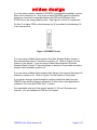
If you are using a sensor network of DS1820's for temperature readings, connect
them now to connector J2. Only 2 pins of each DS18S20 need be connected,
however a connection is required between the VDD and GND pins of the
DS1820 if you are using parasitic power. See Figure's 1 and 2 for connections.
On Rev G or higher PCB’s, a third terminal on J2 is provided for distributing +5V
to the one-wire bus.
.
Figure 1 DS18S20 Pin-out
If you are using a Dallas Semiconductor One-Wire Weather Station Version 1,
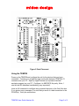
then remove the jumper H1 located on connector J4. Refer to Figure 2 for the
location of this jumper. If you are using a Dallas Semiconductor One-Wire
Weather Station Version 3, then add jumper to position H3 and make sure that a
jumper is also installed in position H1.
If you are using a Dallas Semiconductor Rain Gauge, then remove the jumper H2
located on connector J4. Refer to Figure 2 for the location of this jumper.
If you require stronger signal strength for sensors located far away from the
TEMP05, then install a jumper to connector J5 (Note: this is only applicable to
software 4.20 or less and PCB’s Rev F or lower).
Pre-assembled versions of this project include H1, H2 and J5 jumpers preinserted. J5 is not available on PCB rev G or higher.
TEMP05 User Guide Version Hb
Page 2 of 9