1
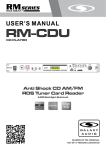
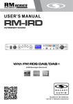
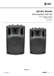
G-SERIES
USER'S MANUAL
G-SERIES
AMPLIFIERS
G-440, G-850, G-1200
G-440
G-850
G-1200
IMPORTANT SAFETY INSTRUCTIONS
1.Read these instructions before using the product.
2.Keep these instructions.
3.Heed all warnings.
4.Follow all instructions.
5.Do not use this apparatus near water.
6.Clean only with dry cloth.
7.Do not block any ventilation openings. Install in accordance with the manufacturer's instructions.
8.Do not install near any heat sources such as radiators, heat registers, stoves, or other apparatus
(including amplifiers) that produce heat.
9. This product, either alone or in combination with a mixer, headphones or speakers, may be
capable of producing sound levels that could cause permanent hearing loss. Do not operate for a long
period of time at a high volume level or at a level that is uncomfortable. If you experience any hearing
loss or ringing in the ears, you should consult an audiologist.
10. Do not defeat the safety purpose of the polarized or grounding-type plug. A polarized plug has two
blades with one wider than the other. A grounding type plug has two blades and a third grounding prong.
The wide blade or the third prong are provided for your safety. If the provided plug does not fit into your
outlet, consult an electrician for replacement of the obsolete outlet.
11. Protect the power cord from being walked on or pinched particularly at plugs, convenience
receptacles, and the point where they exit from the apparatus.
12. Only use attachments/accessories specified by the manufacturer.
13. Use only with the cart, stand, tripod, bracket, or table specified by the manufacturer, or sold with the
apparatus. When a cart is used, use caution when moving the cart/apparatus combination to avoid injury
from tip-over.
S3125A
14. Unplug this apparatus during lightning storms or when unused for long periods of time.
15. Refer all servicing to qualified service personnel. Servicing is required when the apparatus has been
damaged in any way, such as power-supply cord or plug is damaged, liquid has been spilled or objects
have fallen into the apparatus, the apparatus has been exposed to rain or moisture, does not operate
normally, or has been dropped.
16. Do not expose this apparatus to dripping or splashing and ensure that no objects filled with liquids,
such as vases, are placed on the apparatus.
17. To completely disconnect this apparatus from the AC Mains, disconnect the power supply cord plug
from the AC receptacle.
18. The mains plug of the power supply cord shall remain readily operable.
The lightning flash with arrowhead symbol within an equilateral
triangle, is intended to alert the user to the presence of uninsulated
"dangerous voltage " within the product's enclosure that may be of
sufficient magnitude to constitute a risk of electric shock to persons.
The exclamation point within an equilateral triangle is intended to
alert the user to the presence of important operating and
maintenance (servicing) instructions in the literature accompanying
the product.
WARNING: To reduce the risk of fire or electric shock, do not
expose this apparatus to rain or moisture.
Contents
INSTRUCTIONS AND INSTALLATION....................................................................1 & 2
SOUND REINFORCEMENT BASICS......................................................................3 & 4
FRONT PANEL............................................................................................................5
REAR PANEL...............................................................................................................6
CONNECTION EXAMPLES....................................................................................7 & 8
CONNECTION CABLES...............................................................................................9
SPECIFICATIONS.....................................................................................................10
Thank you for choosing the G-SERIES amplifiers!
The G-SERIES power amplifiers have been designed to provide great efficiency, dynamics and
reliability at a very affordable price, for a variety of fixed and mobile audio applications.
The G-SERIES circuitry and selected components offer excellent sound quality and high fidelity
audio reproduction. The compact design improves the price/performance ratio, while the rugged
metal chassis guarantees maximum sturdiness. The G-SERIES amplifiers are available in three
models.
G-440
G-440
2 x 210 watts @ 4 ohms
G-850
2 x 350 watts @ 4 ohms
G-1200
2 x 635 watts @ 4 ohms
The G-SERIES amplifiers are equipped with a highly visible LED display system, which provides
precise information on signal status in any lighting condition. The connection system includes XLR
and TRS 1/4" JACKS for audio input and twist-lock connectors for power outputs. Standard 19" rack
mountable sturdy metal chassis makes installation easy while providing maximum protection.
INSTRUCTIONS AND INSTALLATION
ATTENTION !!!
The G-SERIES amplifiers generate high voltage on output.
To avoid the risk of electric shocks. DO NOT TOUCH any bare
wires when the unit is switched on.
This manual contains important information for correct safe use,
read it carefully before using your amplifier.
Connection to main power supply
Before connecting the amplifier to a power socket, always make certain that:
1. The electric system and power socket have adequate grounding compatible with the safety
norms (if you are uncertain, consult specialized personnel);
2. The power supply voltage corresponds to that shown on the rear of the unit (an allowance of up
to +/-10% is accepted);
3. The power cord is not damaged and has no bare wires;
4. The on/off switch is in the off position.
Make sure the amplifier is also off before disconnecting the power cord from the main power
socket.
Switching on and off
In your sound reinforcement system, always switch on the amplifier after all the other equipment
and always switch it off before anything else, if possible with the gain controls set at minimum: this
will avoid annoying and sometimes dangerous signal peaks.
Installation and use
This amplifier generates high power, so install it in locations which ensure correct air circulation.
Avoid long exposure to direct sunlight, sources of strong heat, powerful vibrations, very dusty or
particularly damp surroundings or rain: this will prevent possible faulty operation, deterioration or
even electric shocks and fires. The air for cooling the unit is forced in through the vents in the front
panel and out through those on the rear panel, so make certain that there's sufficient space
around the amplifier to allow adequate air circulation.
If racks or flight-cases are used, make sure that airflow is unobstructed: do not install the amplifier
in racks or flight-cases with closed backs. Since part of the heat is dissipated via the metal bottom
of the amplifier, it's advisable to install the amplifier with at least one rack unit space between
them.
Audio connections
Remember to always connect and disconnect other units with the amplifier switched off. Always
use good quality cables of the appropriate type, described in the "connection cables" chapter of
this manual.
Take care of your connector cables, which are a frequent cause of problems. Check their condition
frequently. Always grip them by the connector, avoid pulling them forcefully and coil them without
forming knots or sharp bends: they'll last longer this way and be more reliable.
1
INSTRUCTIONS AND INSTALLATION
Preventing or identifying interference
First of all, check that the amplifier is installed in a place free from industrial or RF (radio
frequency) interference. Avoid installing your equipment very near TV sets, mobile phones, etc., as
these can cause noisy interference.
When connecting the other components of your sound system, watch out for "ground loops",
which could cause hum and jeopardize the amplifier's excellent signal-to-noise and low distortion
characteristics. The best way to avoid ground loops is to connect the electric ground of all the
equipment to a single central point (the so-called "star" system).
Protection and maintenance
The amplifier is built in shock-resistant material. Nevertheless, protect it during transport with a
flight-case to avoid the risk of any casual accidents. After long periods of use, particularly in dusty
surroundings, accumulated dust may interfere with the unit's cooling. Without opening the amplifier
and making certain it's disconnected from the mains supply, dust can be removed with a jet of
compressed air, forcing it out through the chassis louvers. If the dust build-up is excessive, don't
open the amplifier, as you could run the risk of serious electric shocks: contact Galaxy Audio
Any dust on the outside of the chassis should be removed using a dry soft cloth or brush. Never
use alcohol, acetone or solvents of any kind.
The amplifier requires no further maintenance.
In the event of breakdown
All user-adjustable parts are external and easily accessible. Never open the amplifier: you could
run the risk of serious electric shocks. In the event of breakdown, contact Galaxy Audio. 1 (316)
263-2852 or at [email protected]
Keep this user's manual for future consultation.
2
SOUND REINFORCEMENT BASICS
OHM’S LAW
and the G-Series Amps
The SPEAKER OUTPUT jacks on the G-Series amps are designed to power up to two
Core (or other brand) 8 ohm speakers, or up to four Hot Spot 16ohm speakers per channel.
Most professional-type speakers (like the Core and Hot Spot) have two jacks which are
wired in parallel (meaning the signal can travel into one jack and out of the other). Think of
each speaker as a “load” added to the amplifier, the greater the number of speakers, the
heavier the load. Adding too many speakers can overload the amplifier, causing it to
overheat and distort. This will not only sound bad but it can damage the amplifier, the
speakers, or both.
One easy way to determine the load on the amplifier is to use Ohm's law, which states:
“The total impedance of N speakers in parallel is equal to the reciprocal of the sum of the
reciprocals. In equation form:
Where Z1 is the impedance (or ohm rating) for the first speaker, Z2 is the impedance for
the second, and so on for every speaker in the chain. This equation calculates the total
impedance of the speaker system, which should NOT be lower than the minimum
impedance rating of the amplifier.
1
Z(Total)=
1
1
1
1
1
___
+ ___ + ___ + ___ + ___
Z1
Z2
Z3
Z4
ZN
The G-Series amps are rated for loads as low as 4 ohms per channel. Therefore, the total
impedance of the speaker system must be greater than, or equal to, 4 ohms. Anything less
will overload the amplifier. For one pair of speakers use the short form of the equation: the
product of the two speakers divided by the sum of the two speakers is equal to the total
impedance or the equivalent impedance of the speaker system.
Z=
Z1 x Z2
Z1 + Z2
This equation may be used to calculate the equivalent impedance for additional speakers in
two-speaker increments. Determine the impedance of the first two speakers, substitute Z
total for Z , and include the next speaker. Repeat the process until all speakers have been
included. The result should be the same as with the first method. A word of caution: polarity
rules must be observed when connecting multiple speakers. Polarity will not affect the Z,
but can affect the quality and volume of the sound. If you are having problems with any of
these applications use Galaxy Audio's CRICKET Polarity and Continuity Test Set to check
the polarity of your cables.
3
SOUND REINFORCEMENT BASICS
EXAMPLE 2 USING GALAXY HOT SPOTS:
As long as all of the speakers have the same impedance rating, the equivalent impedance
of the system is the rated impedance of one speaker divided by the number of equivalent
speakers.
16 x 16
Z=
= 8 Ohms for two HOT SPOTS
16 + 16
8 x 16
Z=
= 5.33 Ohms for three HOT SPOTS
8 + 16
5.33 x 16
Z=
= 4 Ohms (the total load)
5.33 + 16
4
FRONT PANEL
G-440
POWER ON/OFF
BRIDGE
LED for indicating the work mode of the amplifier. This LED will light when the bridge
switch at rear panel on the bridge position.
INPUT ATTENUATORS
Input gain potentiometers, with 40 detented steps, attenuate the level of the external signal
sent to the respective channels of the amplifier.
SIGNAL LEDS
Indicators of signals on output. If lit, indicate that the relative outputs of the amplifier
channels are sending an audio signal.
CLIP LEDS
Amplifier CLIPPING indicators indicate the clipping of the amplifier, i.e. when the audio
signal level exceeds the output capacity of the amplifier channel. When these LEDs flash
reduce the input signal level.
5
REAR PANEL
INPUTS
Each channel has (1) balanced XLRF and (1) balanced TRS ¼" input connector. These
can receive balanced or unbalanced line level signals.
LINK
The XLRF and TRS ¼" channel connectors are wired in parallel to facilitate daisy chaining
of channels.
OUTPUTS
Twist-Lock connectors (minimum impedance 4ohm).
The Twist-Lock connectors are wired: PIN 1+ positive signal, PIN 1- negative signal.
BRIDGE OUTPUT Twist-Lock connector (minimum impedance 8ohm). PIN 1+ power
output signal positive PIN 1- power output signal negative
NOTE: to avoid possible damage to the loudspeaker enclosures, only connect enclosures or speaker
systems compatible with the power load and impedance limits indicated for the amplifier (regarding this,
consult the "Specifications" chapter for reference to your specific amplifier model). Use only stranded twisted
pair minimum 18 gauge cables.
AC
Attached power cable
FUSE
Holder for fixing power fuse
Note: replaced with the same fuse or reference the manual.
STEREO/BRIDGE
This slide switch is for selecting amplifier configuration. In the stereo position it has two
independent channels. In the bridge position the channels are combined to form a single
channel amplifier of greater power. In the bridge mode the minimum impedance load
should be no less 8ohms.
GND switch
This slide switch is used for connecting the input Pin 1 to either circuit ground or chassis
ground, this can be useful in eliminating ground loops between the amplifier and other
active devices.
6
CONNECTION EXAMPLES
7
CONNECTION EXAMPLES
8
CONNECTION CABLES
The following diagrams show the wiring of the connectors that can be used with G-Series
amplifiers. To connect the mixer outputs to the amplifiers inputs, make certain to always use
balanced signal cables: the use of unbalanced cables could cause annoying hum and noise. To
connect the amplifier to the loudspeaker enclosures always use stranded twisted pair cables. For
8 ohm loads use 18 gauge or larger cables, and for 4ohm loads use 14 gauge or larger. Keep runs
as short as possible and use the largest gauge possible.
Take care of your connector cables, always gripping them by the plugs and avoid pulling them
directly. Always you're your cables carefully to avoid knots, kinks, and tight bends. Periodically
check that your cables are in good condition, correctly wired and with clean contacts. The majority
of audio problems are caused by the use of unsuitable or damaged cables.
Balanced 1/4" TRS signal connector
Balanced XLR-M signal connector
Twist-Lock signal connector
9
SPECIFICATIONS
POWER SPECIFICATIONS
G-440
G-850
G-1200
8 ohm
2 x 145
2 x 240
2 x 400
4 ohm
2 x 210
2 x 340
2 x 660
Bridge 8 ohm
440
850
1200
G-440
G-850
G-1200
Rated Power Output
1KHz, THD < 0.5%
ELECTRICAL
SPECIFICATIONS
1.0 VRMS
Input Sensitivity
Input Impedance
10 Kohm (balanced)
Frequency Response
-0.5dB (20-200000Hz)
Voltage Gain
31dB
33dB
Slew Rate
22V/us
Damping Factor
>400:1 @ 1KHz, 8 ohms
Cross Talk
-82dB (1KHz)
S/N Ratio
98dB
Harmonic Distortion THD
<0.1% (20~20000Hz)
Intermodulation Distortion
<0.1% (SMPTE method, 60Hz & 7KHz, 4:1 ratio)
GENERAL
SPECIFICATIONS
G-440
G-1200
G-850
Protections
Power transformer thermal protection
Protections Short circuit protection
Power on or off and DC output protections
Controls
ONIOFF switch
Input level control for each channel
Power on: 1 red LED
Indicators Signal: 2 green LED, 2 red LED
Indicators
IN
Connectors
1 XLR·F + 1 1/4" TRS in parallel for each channel
Connectors 1 4·way Twist-Lock for each channel1 4·way Twist-Lock for bridge output
OUT
Power Supply
10
35dB
See label on Amplifier
Dimensions (WxHxD)
Inches
(mm)
19" x 3.48" x 13.1"
(482 x 88.5 x 333)
19" x 3.48" x 17.13"
(482 x 88.5 x 435)
19" x 3.48" x 18.25"
(482 x 88.5 x 463)
Weight
Lbs (Kg)
28.66 lbs (13Kg)
36.38 lbs (16.5Kg)
49.6 lbs (22.5Kg)
G-SERIES
AMPLIFIERS
USER'S MANUAL
ONE YEAR LIMITED WARRANTY
WARRANTY Information can be viewed online at
http://www.galaxyaudio.com/warranty.php
1-800-369-7768
www.galaxyaudio.com
Specifications in this manual are subject to change without notice.
© Copyright Galaxy Audio 2012
Printed in China
V10092012