1
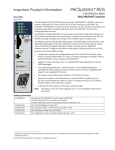
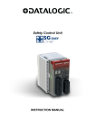
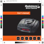
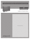
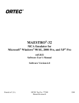
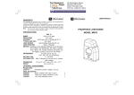
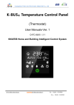
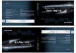
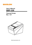
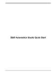
SBS -600 Graphical Digital Multimeter SBS- 700 Multi-Function Oscilloscope Quick Start Guide 99 Washington Street Melrose, MA 02176 Phone 781-665-1400 Toll Free 1-800-517-8431 Visit us at www.TestEquipmentDepot.com Quick start guide will explain basic information about the unit. For complete Operation and Safety Information, Please refer to the SBS-600/700 Quick Start Guide Revision 1.0 -5/2014 1 User Manual supplied on the CD-Rom included with the Quick start guide. “READ THE USERS MANUAL PRIOR TO OPERATION” "Pay special attention to the SAFETY Information sections of the Quick start guide and the user’s manual” Attention Attention mark is displayed to draw ATTENTION during use. Meter could be damaged or important Data may be lost if the unit is used improperly. Warning Warning mark is displayed to indicate improper use. Operating outside of equipment ratings could cause serious personal injury or fatal death. [Safety Symbol] Table lists and describes the safety symbols shown on Meter or in User Manual. : DC (Direct Current or Voltage) : AC (Alternating Current or Voltage) : DC and AC : Earth Ground : Double Insulation : Power Supply OFF : Power Supply ON : Warning of Electric Shock : Warning of Danger : CategoryⅡ 1000V Overload Protection(Multi-meter Function :Model SBS-600 SBS-700 ) : CategoryⅢ 600V Overload Protection(Multi-meter Function Model SBS-600, SBS-700) : CategoryⅢ 300V Overload Protection(Scope Function, Model . SBS-700) : [Notes for Safe Operation] WARNING: USE EXTREME CAUTION IN THE USE OF METER The improper use of meter may result in injury or death. Follow all safeguards in this manual, in addition to the normal safety precautions used in working with live electrical circuits. DO NOT ATTEMPT TO SERVICE the meter if you are not qualified to do so. 2 Test Equipment Depot - 800.517.8431 - 99 Washington Street Melrose, MA 02176 - TestEquipmentDepot.com [WARNING ] Pay attention when testing conditions exceed 60V DC, 30V AC rms or 42.4V AC Peak that can cause an electric shock. Do not connect the Ground wire to voltage higher than 0V DC, 30V AC rms or 42.4V AC Peak. Use only the proper accessories supplied with the meter. Rechargeable Battery Pack, AC Power Adapter and Internal Charger, Test Lead, Probe, Logic/Signal Cable set. Warranty will not cover Meter Measurement failure or damage from improper accessories other than supplied by manufacturer of the Meter. Connect and disconnect properly. Connect Test Leads, Probes or Cables to the Meter before connecting to the active circuit to be tested. Disconnect Leads, Probes or Cables from the test circuit prior to disconnecting them from the meter. Testing Probe always connected with Testing Circuit in series. Replace the Ni-MH Battery Pack only with an equivalent from the Manufacturer. Remove AC Power Adapter, Test Lead, Probe and Cable from Meter when replace the Battery. When the Battery Warning Symbol is blinking on the display, the measurement may display in error. Recharge the battery or replace. Observe all terminal ratings. Observe all rating and marking oin the Meter. Refer to Operator manual for detailed information. [ Max Input Voltages] - Scope Input: 300V CATⅢ. - Meter Input: 600V CATⅢ. Do not apply any voltages when measuring OHM (resistance) or Capacitance for the Meter Mode. Do not use Meter where in or near explosive, flammable, wet or damp environments. Do not use Meter with the Case Cover open for any reason. Fuses should only be replaced with the proper size and rating as specified in the manual. Do not expose circuit. [ATTENTION] Before testing in Resistance, Capacitance, Continuity or Diode modes, disconnect any power supply to the circuit being tested and discharge High Voltage Rated Capacitance. Do not attempt Voltage measurement while measuring Current. [ENVIRONMENT] The Meter is designed Indoor use in following environment conditions Operating Temperature: 32°F - 122°F (0°C ~ 50°C) Guaranteed Accuracy Temperature: 73.4°F +/- 41°F (23 0°C +/- 5°C) Operating Humidity: 80% R.H. or less Storage Temperature: 32°F - 158°F (0°C ~ 70°C) Altitude : 2000m CAT III 600V Pollution Degree : 2 3 WEEE (Waste Electrical and Electronic Equipment) (2002/96/EC) Meter complies with WEEE (2002/96/EC) requirements. Do not dispose Electric / Electronics device with other trash. Front View Key Pad The Keys are different by models. [Main Functional Keys] 4 SBS - 600 SBS - 700 Function and Menu selections automatically take effect 2 seconds after pressing the key. If the user Prefers immediate setting Pressing the ENTER key will immediately select the Function or Menu. Voltage measurement keys : AC+DC, DC, AC Current measurement keys : AC+DC, DC, AC Resistance, Continuity, Diode Check key Capacitance measurement key Auxiliary measurements (Temperature, Relative Humidity, Hi-Currents. Pressure) with use of optional accessories not included. Square wave signal out put Oscilloscope Protocol Analyzer Pattern Generator Logic Analyzer 5 [Secondary Function Key] [ Secondary Function Keys ] Function key Function Description Selects Sub Menu functions and modes after (main) Menu selection. Upper Line: (Short Key) One Touch press Enter Menu (Main Menu) functions and modes. Lower Line: (Long key) Press longer than 2 seconds to enter USER. To return to Menu, press Exit key Upper Line : Meter setup Auto Ranging mode Lower Line : (Long key) Press longer than 2 seconds to enter Manual measurement mode (Range) - In Manual Range, range up/down can be selected with a Short key press (One touch) - To return to Auto measurement mode, hold key down (longer than 2 seconds) Upper Line: (Short Key) One Touch press enter Data Logger mode. Lower Line: (Long key) Hold longer than 2 seconds to enter Save (Data) and Recall (Data) mode. Save or Recall selection change available at sub-mode. - Press Short Key to change Logger Mode. - Press F4 Exit to leave Logger mode. Upper Line (Manual Hold): (Short Key) One touch press to enter Hold/Run mode. Hold the present measurement value in Display and can save the value. Change Hold or Run can be done (Short Key) One Touch press. Lower Line (Automatic Hold) : (Long key) Hold longer than 2 seconds to enter Auto Hold mode. 6 Test Equipment Depot - 800.517.8431 - 99 Washington Street Melrose, MA 02176 - TestEquipmentDepot.com I (Help): (Short Key) One Touch press to enter Help mode. Brief Information on present function is displayed. Back Light On/Off: Hold longer than 2 seconds to enter Back Light display mode. Help: short key(50ms), Backlight: long key(2s) Turn the meter power ON / OFF Hold Longer than 2 seconds to power ON / OFF Cursor buttons select an item in Menu. Adjust Display Ratio. Scroll the information and Input Data LCD Display Scope Screen No Symbol Description 1 RUN Present measurement is proceeding and working. 2 HOLD Measurement is being held momentarily 3 V/div Volt (Vertical Axis) Division indicator 4 T/div Time (Horizontal Axis) Division indicator 5 Trigger Trigger indicator for Level, Position or Edge direction 6 Coupling Input Coupling selection (DC/AC) 7 Peak Peak Detection selection (ON/OFF) 8 V/Position Volt (Vertical Axis) Position adjustment 9 T/Position Time (Horizontal Axis) Position adjustment 10 Trig Level Trigger Level adjustment 7 DMM Screen No Description symbol 1 Minimum. Maximum, Average measurement 2 Can select Measuring Range in Automatic method or Manual method 3 Freeze the present reading in display. 4 Freeze the present reading in display. 5 Sub Menu 6 Bar-Graph The Subsidiary Menu. After main menu selected, sub menu tree show up to select Input Signal is displayed in Bar-Graph. refer details " Bar-Graph page ) 7 Compare with a reference value and display the Difference. 8 Negative Reading 9 Input Over Voltage warning that exceeds the defined safety protection voltage 10 Remaining Battery Capacity level to use. 11 Being connected with AC Power Adapter. 12 Sampling, Run time 13 Measurement mode.(DCV, ACV, Ohm, Capacitance, Diode) 14 Audible signal is active 15 16 17 (Bar Scale) Secondary measurement Range of Meter secondary measurement information of Input Signal (Hz. ㏈m) Unit symbol is displayed at right side of the measurement 8 Data Logger Screen No Symbol Description 1 Measuring Mode. (DCV, ACV, Ohm, Capacitance, Diode) 2 RUN and STOP of Data Logger function 3 Run Time 4 Accumulated Sample Q‘ty in Data Logger. 5 Maximum Display Range 6 Minimum, Maximum , Average of the Samples 7 Total Time Scale of Data Logging. 8 Present Measurement Value 9 Change the Time Scale (left - right horizontal axis) to review closely on the specific Time Zone. 10 Zoom (at Regular Ratio) the specific waveform quickly (up/ down Vertical axis). 11 Data Logger Data Logger Display 9 Logic Analyzer Screen Protocol Analyzer Screen [Logic Analyzer, Protocol Analyzer Display Symbol] No Symbol Description Logic Analyzer: Pattern, Duration 1 Condition Protocol Analyzer: CAN, LIN, I2C, UART, USB, I2S SMBus, SPI, DMX512, 1-Wire 2 Time/div Measurement Time/div Indicator 3 Channels Displays all the Input Channels 4 Horizontal Time Division & Position adjustment 5 Trigger Trigger Mode, Source, and Trigger Level adjustment 6 Cursor Horizontal Cursor adjustment 7 Condition Detailed condition setting for each Logic or Protocol type 8 Information Display window to show the trigger condition or channel input information of each type 10 Pattern Generator [Pattern Generator Display Symbol] No Symbol Description 1 Condition UART, CAN, User Defined 2 Time/div Measurement Time/div Indicator 3 Channels Displays all the Channels (TX/RX) 4 View 5 Condition 6 Message Used for making the format, cycle, and data of each pattern 7 Output Selection of signal out or not 8 Information Selection of Transaction/Message, Acquisition Mode, and Cursor adjustment Selection of Trigger condition, Trigger Level, and Baud rate used to decide the speed of pattern Display window to show the information of In/Out Transaction or all the memorized messages [BAR-GRAPH] BAR-GRAPH display Measurement Data in Analogue Meter Display type. Can update 15 times / second. Response Time of Analogue display is faster than Digital display which Bar -Graph display is very efficient to observe display like as PEAK that input change very fast. “Pattern Generator, Current Generator, logic Analyzer, MIN/MAX” modes do not activate BAR-GRAPH display. 11 Direct Voltage, Currents and Relative display BAR-GRAPH “0” center position. At Direct Voltages and Currents, BAR-GRAPH total scale displays the Maximum of the selected measurement range. Displayed Segment indicates Measurement Size which is displayed within the Maximum Scale of the selected range. When measured value exceeds the maximum scale of the selected range, ▶ is displayed at RIGHT of BAR-GRAPH. When Direct Voltage or Current, ◀ is displayed at LEFT of BAR-GRAPH at negative MAX and ▶ is displayed at RIGHT of BAR-GRAPH at positive MAX [Measurement Status display] Status icon is displayed at top of Display. - Battery status, Present Measurement Value, Buzzer (Continuity), Data Hold, Auto Hold, AC Power Adapter Connected. [Display] Display consist of Main Measurement Display, BAR-GRAPH display, Sub function display (Sub measurement or Data) [Sub Menu Key] 4 keys (F1 ~ F4) underneath of Display. Selected functions available depend on measurement function or menu. Input Terminals To prevent from Damage, Do not apply exceeding the Rate. SBS - 600 ** CAT III 300 V for Scope input SBS - 700 12 Test Equipment Depot - 800.517.8431 - 99 Washington Street Melrose, MA 02176 - TestEquipmentDepot.com Input Terminal Connection Measurement Input Terminal 10A 0 A ~ 10.00 A currents. (10A overload, 30sec On, 10 sec OFF) mA 0 A ~ 500 mA Currents measurement. COM Negative Terminal to all measurements. SCOPE, V, Ω, ㎐, Sig-out( ) Volts, Continuity, Resistance, Diode, Capacitance, Frequency measurement and AUX (auxiliary function with external adapter : Temperature, High Current, Relative Humidity, Pressure measurement) 13 pin socket Terminal ( SBS-700) 13 pin socket Terminal (Measurement and Output) : Logic Analyzer, Pattern Generator, Protocol Analyzer, Sig- Out Rear View and Side View 13 Logic, Pattern, Protocol, Signal Out - 13 Pin Cable Connection Pin No Function Pin No Function 1 Ground(Black/Clip) 9 Ground(Black/Hook) 2 Signal out(Red/Clip) 10 N/A 3 N/A(pin cutting) 11 N/A(pin cutting) 4 Logic5(Blue/Hook) 12 Logic1(Blue/Hook) 5 Logic6(Blue/Hook) 13 Logic2(Blue/Hook) 6 Logic7(Blue/Hook) 14 Logic3(Blue/Hook) 7 Logic8(Blue/Hook) 15 Logic4(Blue/Hook) 8 Pattern Generator RX(Red/Hook) 16 Pattern Generator TX(Red/Hook) Voltage Warning User should pay attention at the Voltage Rating and Over Voltage warning. Immediately remove the Test Lead/Test Probe from the METER when VOLTAGE WARNING comes on. Scope function Input (model SBS-700), max 300V. Other Multi-meter function Input (models SBS-600, SBS-700 ), max 600V. 14 Meter displays VOLTAGE WARNING regardless of AUTO or MANUAL measurement. When over the Maximum Measurement limit, the WARNING sound starts. At this case, immediately remove Test Lead/Test Probe from the Meter. When measurement range set manually. If the measurement exceeds the range, the display will show “OL”. Power 6*AA Alkaline Battery ( SBS-600 only ) 7.2V NiMH Battery Pack or AC Power Adapter ( SBS-700 only ) Remaining Battery Capacity Level indicator Top right display indicates Remaining Battery Capacity Level, Level Remaining Battery Fully Charged. (100%) 3/4 charged (75 %) 1/2 charged (50 %) 1/4 charged (25 %) Depleted ( 0 %) Auto Power Off During operation the unit will automatically power off after 15 minutes without a button push. User can select the Auto Power Off time (min 5 minutes ~ max 2 hours or Auto Power Off mode). [NOTE] Auto Power Off mode is not active in DATA LOGGER mode (MIN MAX, PEAK mode in operation) Auto Power Off mode is not active when the Meter is powered by ADC Power Adaptor (SBS-700 only) Battery Save Mode Auto Power Off mode is not activated during Data Logger or Auto Hold mode of operation. If no key is pressed on Meter for a certain time, Meter automatically changes to Battery Save Mode. Mode Change time is equal to Auto Power Off mode time setting. All Power off including Display, except present measurement function. Exit the Battery Save Mode by - Pressing any key - change measurement range - start PC Interface communication. Meter function and Operation Mode is not changed 15 Back Light Display When measurement environment is dark or it is hard to see the LCD display, hold Back Light key longer than 2 seconds, Back Light operation time can be set in USER mode Measurement Range selection (Auto/Range) Selected Measurement Range is shown at the Right of the BAR-GRAPH. If press change AUTO Range mode or Manual Range mode. When press the Range mode, measurement range is set automatically. key, at MANUAL [NOTE] Key is not active in Capacitance, Diode, or Frequency measurements which are always set to automatically Auto Ranging. Manual Range mode can be converted to Auto Range mode by holding than 2sec. Auto Range mode can be converted to Manual Range mode by holding more than 2sec. In manual mode, Up/Down. the Up/Down key is activated by each press key for more key for – each step MENU After main function DSO is selected, press MAIN Menu to select Channel, Trigger, Measure, Cursor After Main Menu selected, Select Sub Menu F1, F2, F3, F4 to proceed to desired measurement. General Maintenance Wet or Dusty Input Terminals can cause incorrect measurement readings. Cleaning procedure is as follows. ①Power off the Meter and separate Test Lead/Probe from Meter. ②Reverse the Meter Top Side and Bottom Side and remove the dust in the terminal by shaking the meter. ③ Clean the Exterior Cases with soft detergent or wet cloth. Do not use Solvent or an abrasive. ④ Clean cotton swab wet with Alcohol may be used to clean out the surface of Input Terminals. To ensure proper measurements, make sure to use the correct input terminals for that type of measurement.. Do not test voltages above the ratings of the meter inputs.. Battery Replacement Do not short or reverse the polarity to discharge Battery. Do not attempt to recharge, non-rechargeable batteries. 16 [Note] Model SBS-600 uses only 6 * AA, 1.5V Alkaline battery - Non Rechargeable Battery. Model SBS-700 uses only the supplied 7.2V NiMH Rechargeable Battery Pack. When Battery low signal is blinking, In the model SBS-600, replace with New AA Alkaline battery cell as soon as possible. In the model SBS-700, recharge the battery pack as soon as possible. If Battery is completely depleted, and needs to be replace with a new battery, please replace battery using the following procedure. ①Remove the Holster Case from the Meter. ②Remove Battery Cover from the Rear Case of the meter. ③Replace Battery and be sure to connect correct polarity inside the battery compartment. ④Close Battery Cover and assembly in reverse order of above when opening Battery Compartment Battery Charge (model SBS-700 only). Do not discharge battery with reverse polarity. Do not use any other Rechargeable Battery. Use only the 7.2 V NiMH battery pack supplied from original manufacturer. Connect the Battery with the proper polarity. When charging the battery, use only the AC Adapter and Internal charger supplied from the original manufacturer. Please follow Battery Charging procedure. ① Connect the DC Power adapter to Power Outlet. ② Plug charging connector into the SBS-700. ③ When Charging is completed, “FULLY CHARGED” message is displayed on the screen. ④ If Battery is fully charged, disconnect DC Power Adapter. ⑤ Do not charge Battery while meter is being use Fuse Replacement If the Fuses open due to fault, Replace fuses using the procedure below ; ①Power off the Meter. Disconnect Test Lead from Meter. ②If DC power adapter is connected, disconnect the adapter from the meter. ③Separate Battery Cover from meter. ④Pull out one end of defect Fuse from Fuse Clip. ⑤Replace with same size and rating Fuse. Fuse should be placed in center of Fuse Clip. ⑥Do not touch any other component besides Fuse. ⑦Assemble the Battery Cover to the meter ⑧Fuse Ratings and Dimensions are as below ; [Fuse Rating and Dimensions] 500mA/250V 5mm × 20mm (FF) 1OA/250V 6.3mm × 32mm (FF) 17 Test Equipment Depot - 800.517.8431 - 99 Washington Street Melrose, MA 02176 - TestEquipmentDepot.com