1
dot User’s Manual, January 5, 2015
F
36
Attributed DOT Format (-Tdot)
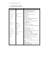
This is the default output format. It reproduces the input, along with layout information for the graph. Coordinate values increase up and to the right. Positions
are represented by two integers separated by a comma, representing the X and Y
coordinates of the location specified in points (1/72 of an inch). A position refers
to the center of its associated object. Lengths are given in inches.
A bb attribute is attached to the graph, specifying the bounding box of the
drawing. If the graph has a label, its position is specified by the lp attribute.
Each node gets pos, width and height attributes. If the node is a record,
the record rectangles are given in the rects attribute. If the node is polygonal
and the vertices attribute is defined in the input graph, this attribute contains
the vertices of the node. The number of points produced for circles and ellipses is
governed by the samplepoints attribute.
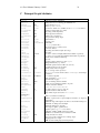
Every edge is assigned a pos attribute, which consists of a list of 3n + 1
locations. These are B-spline control points: points p0 , p1 , p2 , p3 are the first Bezier
spline, p3 , p4 , p5 , p6 are the second, etc. Currently, edge points are listed top-tobottom (or left-to-right) regardless of the orientation of the edge. This may change.
In the pos attribute, the list of control points might be preceded by a start
point ps and/or an end point pe . These have the usual position representation with a
"s," or "e," prefix, respectively. A start point is present if there is an arrow at p0 .
In this case, the arrow is from p0 to ps , where ps is actually on the node’s boundary.
The length and direction of the arrowhead is given by the vector (ps − p0 ). If there
is no arrow, p0 is on the node’s boundary. Similarly, the point pe designates an
arrow at the other end of the edge, connecting to the last spline point.
If the edge has a label, the label position is given in lp.