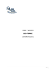
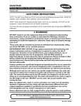
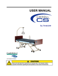
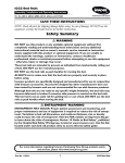
1
Owner’s Operator and Maintenance Manual
ValueCare Bed Series
Single Motor Semi-Electric Bed
DEALER: This manual must be given to the user
of the bed.
USER: Before using this bed, read this manual
and save for future reference.
For more information regarding
Invacare products, parts, and services,
please visit www.invacare.com
WARNING
DO NOT use this product or any available optional equipment without first
completely reading and understanding these instructions and any additional
instructional material such as owner’s manuals, service manuals or instruction
sheets supplied with this product or optional equipment. If you are unable to
understand the warnings, cautions or instructions, contact a healthcare
professional, dealer or technical personnel before attempting to use this equipment
- otherwise, injury or damage may occur.
The initial set up of this bed must be performed by a qualified technician.
Procedures other than those described in this manual must be performed by a
qualified technician.
For Dealers Only - Set-up and Assembly Instructions are in the rear of this manual.
These procedures must be performed by a qualified technicians only.
ACCESSORIES WARNING
Invacare products are specifically designed and manufactured for use in conjunction
with Invacare accessories. Accessories designed by other manufacturers have not
been tested by Invacare and are not recommended for use with Invacare products.
SPECIAL NOTE
For your convenience, the March 2006 version of the FDA’s bed safety guidelines
are provided in the Appendix. The information from the FDA’s brochure, published
by Hospital Bed Safety Workgroup, is reproduced verbatim, the latest revision of
which is available at http://www.fda.gov.
NOTE: Updated versions of this manual are available on www.invacare.com.
ValueCare Bed Series
2
Part No 1134867
TABLE OF CONTENTS
TABLE OF CONTENTS
REGISTER YOUR PRODUCT ............................................................... 4
SPECIAL NOTES ................................................................................ 5
LABEL LOCATIONS ........................................................................... 6
TYPICAL PRODUCT PARAMETERS .................................................... 7
SECTION 1—GENERAL GUIDELINES ................................................... 8
Important Safety Instructions ..................................................................................................................8
Operating Information...............................................................................................................................9
Replacement Parts/Accessories ............................................................................................................10
Accessories Information .........................................................................................................................11
Bed Rails .....................................................................................................................................................11
Electrical .....................................................................................................................................................12
Repair or Service Information ...............................................................................................................12
Servicing of Double-Insulated Products ..............................................................................................12
Radio Frequency Interference ...............................................................................................................13
Weight Limitations ...................................................................................................................................13
SECTION 2—OPERATION AND ADJUSTMENT .................................. 14
Raising or Lowering the Entire Bed .....................................................................................................14
Using the Pendant.....................................................................................................................................15
SECTION 3—TROUBLESHOOTING .................................................... 16
Troubleshooting Electrical......................................................................................................................16
Troubleshooting Mechanical ..................................................................................................................16
Maintenance Checklist.............................................................................................................................17
Cleaning and Disinfecting the Bed ........................................................................................................17
ASSEMBLY, MAINTENANCE AND ADJUSTMENT SECTIONS FOR DEALERS ONLY ....................................................................... 18
Overview of Procedures.........................................................................................................................18
SECTION 4—PACKAGING, HANDLING, AND SET-UP ........................ 19
Receiving.....................................................................................................................................................19
Unpacking ...................................................................................................................................................19
Inspecting....................................................................................................................................................20
Set-Up .........................................................................................................................................................21
Storing the Beds........................................................................................................................................27
Store the bed in a dry area. ...................................................................................................................27
Part No 1134867
3
ValueCare Bed Series
TABLE OF CONTENTS
TABLE OF CONTENTS
SECTION 5—MAINTENANCE AND CLEANING ................................. 28
Troubleshooting Electrical......................................................................................................................28
Troubleshooting Mechanical ..................................................................................................................29
Maintenance Checklist.............................................................................................................................29
Cleaning and Disinfecting the Bed ........................................................................................................30
Pass/Fail .......................................................................................................................................................30
APPENDIX ..................................................................................... 32
A Guide to Bed Safety Bed Rails in Hospitals, Nursing Homes and Home Health Care: The
Facts....................................................................................................................................................................32
LIMITED WARRANTY ..................................................................... 35
REGISTER YOUR PRODUCT
The benefits of registering include:
1. Safeguarding your investment.
2. Ensuring long-term maintenance and servicing of your product.
3. Receiving updates with product information, maintenance tips and industry news.
Register ONLINE at warranty.invacare.com
Please have your model number and purchase date available to complete your registration.
Any registration information you submit will only be used by Invacare Corporation and protected
as required by applicable laws and regulations.
ValueCare Bed Series
4
Part No 1134867
SPECIAL NOTES
SPECIAL NOTES
Signal words are used in this manual and apply to hazards or unsafe practices which
could result in personal injury or property damage. Refer to the table below for
definitions of the signal words.
SIGNAL WORD
MEANING
DANGER
Danger indicates an imminently hazardous situation which, if not avoided, will
result in death or serious injury.
WARNING
Warning indicates a potentially hazardous situation which, if not avoided, could
result in death or serious injury.
CAUTION
Caution indicates a potentially hazardous situation which, if not avoided, may
result in property damage.
NOTICE
THE INFORMATION CONTAINED IN THIS DOCUMENT IS SUBJECT TO
CHANGE WITHOUT NOTICE.
PENDANT OPERATION
A safety feature of this product includes protection against overheating caused by
excessive or extended periods of operation. Depending on the duration, this
includes multiple or repeated adjustments or the use of multiple functions at one
time. To ensure trouble free operation, always allow a slight pause between multiple adjustments and avoid pressing more than one function button at a time. If thermal protection activation should occur, the bed will not respond to pendant
commands. Given this situation, release the pendant button and allow the bed unit
to sit for several minutes. This will allow the protection function time to reset and
restore bed function. Depending on severity of the initial overheating, this could
take up to 30 minutes.
Part No 1134867
5
ValueCare Bed Series
LABEL LOCATIONS
LABEL LOCATIONS
Serial Number is located on
the side of the bed frame.
ValueCare Bed Series
6
Part No 1134867
TYPICAL PRODUCT PARAMETERS
TYPICAL PRODUCT PARAMETERS
ELECTRIC SPLIT SPRING BED SYSTEM
BED NO.
DESCRIPTION
SHIPPING WEIGHT
VC5310 (Single Motor Bed)
Semi Electric Bed with universal bed ends
153 lbs (69.4 kgs)
SPECIFICATIONS
VC5310
BED END HEIGHT
MINIMUM:
MAXIMUM:
26.00 in (66.0 cm)
34.00 in (86.4 cm)
FABRIC HEIGHT*
MINIMUM:
MAXIMUM:
15.00 in (38.1 cm)
23.00 in (58.4 cm)
OVERALL LENGTH:
88 in (223.5 cm)
BED WIDTH:
36 in (91.4 cm)
SPLIT SPRINGS TO ENDS
HEAD:
FOOT:
43 in (109.2 cm)
45 in (114.3 cm)
ELECTRICAL RATING:
VC5310 - 120V 50/60 Hz, 1.0A
WEIGHT CAPACITY:
450 lbs (204 kg.)
*NOTE: Height from floor to bottom of mattress.
NOTE: This bed is for household/residential use only.
Part No 1134867
7
ValueCare Bed Series
SECTION 1—GENERAL GUIDELINES
SECTION 1—GENERAL GUIDELINES
WARNING
SECTION 1 - GENERAL GUIDELINES contains important information for the safe
operation and use of this product.
Important Safety Instructions
When using the bed, basic precautions should always be followed, including the
following:
Read all the instructions before using the bed.
DANGER - To reduce the risk of electric shock:
1. Always unplug the bed from the electrical outlet before cleaning.
WARNING - To reduce the risk of burns, fire, electric shock, or injury to persons:
1. Unplug from the outlet before servicing.
2. Close supervision is necessary when the bed is used by, or near children
and/or disabled persons.
3. Use this bed only for its intended use as described in these instructions. DO
NOT use attachments not recommended by the manufacturer.
4. NEVER operate this bed if it has a damaged cord or plug, if it is not working
properly, if it has been dropped, damaged, or dropped into water. Return the
bed to a service center for examination and repair.
5. Keep the cord away from heated surfaces.
6. DO NOT use outdoors.
7. Use masked or nasal type oxygen administering equipment only in
conjunction with this bed. The use of ANY other type of oxygen
administering equipment can result in a fire hazard.
8. To disconnect, DO NOT depress pendant buttons.
9. Risk of electric shock - Connect this bed to a properly grounded outlet only.
See Grounding Instructions.
10. Risk of injury to persons - DO NOT place video equipment such as televisions
or computer monitors on bed.
SAVE THESE INSTRUCTIONS
ValueCare Bed Series
8
Part No 1134867
SECTION 1—GENERAL GUIDELINES
Operating Information
DO NOT use near explosive gases.
Keep the product a minimum of 12 inches away from any direct heat source.
Close supervision is necessary when the this bed is used by or near children and
physically challenged individuals.
Possible fire hazard when used with oxygen administering equipment other than nasal or
masked type.
Check all parts for shipping damage and test before using. In case of damage, DO NOT
use. Contact a qualified technician for further instruction.
After any adjustments, repair or service and before use, make sure all attaching hardware
is tightened securely.
If bed is equipped with wheel locks, ALWAYS use wheel locks except when moving the
bed. Inspect for correct locking action on wheel locks before using bed.
DO NOT let any individual underneath the bed or in between the raised bed frame
components at anytime.
When bed is not to be used for an extended period, unplug electric bed from the wall
outlet.
The bed is not designed to be used as a patient transport. When transporting a patient,
use an approved patient transport. Otherwise, injury or damage may result.
After the bed has been assembled, always test to make sure that all sections of the bed are
properly and securely in place before using.
Make sure head and foot springs/sections are connected securely to the universal bed
ends before use.
If the unit is not working properly, call a qualified technician to examine the unit and
repair it.
The electric bed is equipped with locking casters. When transferring into or out of the
electric bed, always lock the locking caster(s). Inspect the wheel locks for correct locking
action before actual use. Even with casters properly locked, some flooring surfaces such
as tile or wood, will allow the bed to move under some conditions. Use on surfaces such
as these must be evaluated by the care provider.
Always remove manual crank(s) before performing electronic functions. Otherwise, the
crank(s) will turn when the motor is on and could cause personal injury or damage to the
bed.
Part No 1134867
9
ValueCare Bed Series
SECTION 1—GENERAL GUIDELINES
ENTRAPMENT WARNING
Proper patient assessment and monitoring, and proper maintenance and use of
equipment is required to reduce the risk of entrapment. Variations in bed rail
dimensions, and mattress thickness, size or density could increase the risk of
entrapment. Visit the FDA website at http://www.fda.gov to learn about the risks of
entrapment. Review “A Guide to Bed Safety”, published by the Hospital Bed Safety
Workgroup, located at www.invacare.com. Use the link located under each bed rail
product entry to access this bed safety guide.
After any adjustments, repair or service and before use, make sure all attaching
hardware is tightened securely. Assist rails with dimensions different from the
original equipment supplied or specified by the bed manufacturer may not be
interchangeable and may result in entrapment or other injury.
Mattress MUST fit bed frame and assist rails snugly to reduce the risk of entrapment.
Replacement Parts/Accessories
Use masked or nasal type oxygen administering equipment only in conjunction with this
bed. The use of any other type of oxygen administering equipment can result in a fire
hazard.
When using nasal or masked type oxygen administering equipment, the oxygen or air
tubing MUST be routed and secured properly to ensure that the tubing does not become
entangled and/or severed during normal operation of the bed.
Always test to make sure that the side rails are properly and securely in place before using
the electric bed.
Invacare recommends that the mattress be centered on the bed frame. Otherwise,
individuals may become entangled between the bed rail and the bed frame.
Physically challenged individuals who cannot prevent themselves from rolling/climbing
out of the this bed may require alternative safe means of restraint.
After raising/lowering the head/foot end of the electric bed, check the distance between
the bottom of the bed rail and the mattress. If there is excessive distance between the
bottom of the bed rail and the mattress in which individuals may become entangled,
adjust the height of the bed rail (if applicable), or provide alternative means of patient
protection.
DO NOT use the side rails as push handles for moving the electric bed.
Traction units MUST be securely fastened to head/foot ends of the bed. These units are to
be used only for immobilizing a patient in various traction setups or assisting the patient
in repositioning or transferring in or out of the bed.
Trapeze units are to be used only for immobilizing a patient in various traction setups or
assisting the patient in repositioning or transferring into or out of bed.
ValueCare Bed Series
10
Part No 1134867
SECTION 1—GENERAL GUIDELINES
NEVER allow patients to use trapeze or traction units as a total individual weight
support.
When operating this bed, ALWAYS ensure that the individual utilizing the bed is
positioned properly within the confines of the bed. DO NOT let any extremities protrude
over the side or between the bed rails when performing these functions.
Keep all moving parts, including the main frame, mattress deck (head and foot
springs/sections) and all drive shafts free of obstruction (i.e. blankets/sheets, heating
blankets/pads, tubing, wiring, etc. and other types of products using electric cords which
may get tangled around the bed, side rails or legs) during operation of the bed.
Replacement mattresses and bed side rails with dimensions different than the original
equipment supplied or specified by the bed frame manufacturer are not interchangeable.
Variations in bed side rail design, width and thickness or firmness of the mattress could
cause/contribute to entrapment. Use only authorized Invacare replacement parts and/or
accessories otherwise the warranty is void. Invacare will not be responsible for any
damage or injury that may result.
Accessories Information
Invacare products are specifically designed and manufactured for use in conjunction with
Invacare accessories. Accessories designed by other manufacturers have not been tested
by Invacare and are not recommended for use with Invacare products.
Bed Rails
These bed rails are intended to prevent an individual from inadvertently rolling out of
bed. DO NOT use for restraint purposes.
Although bed rails are not rated to any specific weight limitation, the bed rails may
become deformed or broken if excessive side pressure is exerted on the bed rails. This bed
rail is not an assist rail for getting into or out of bed. DO NOT use the bed rails as push
handles when moving the bed.
After any adjustments, repair or service and before use, make sure all attaching hardware
is tightened securely. Bed rails with dimensions different from the original equipment
supplied or specified by the bed manufacturer may not be inter-changeable and may
result in entrapment or other injury.
To reduce the risk of entrapment make certain that the bed rail crossbraces DO NOT
exceed the width of the mattress. Mattress MUST fit bed frame and side rails snugly to
reduce the risk of entrapment.
Part No 1134867
11
ValueCare Bed Series
SECTION 1—GENERAL GUIDELINES
Electrical
DANGER
When using an extension cord, use only a three wire extension cord having at least
16 AWG (American Wire Gauge) wire and the same or higher electrical rating as
the device being connected. Use of improper extension cord could result in a risk of
fire and electric shock. Three prong to two prong adapters should not be used. Use
of three prong adapters can result in improper grounding and present a shock hazard to the user.
DO NOT unplug power cord from motor housing.
If a liquid is spilled in or around the electric bed, unplug the electric bed before cleaning.
Clean up the spill and allow the electric bed or the area around the electric bed to dry
thoroughly before using the electric controls again.
The pendant and power cords MUST be routed and secured properly to ensure that the cords
DO NOT become entangled, pinched and/or severed during operation of the electric bed.
NEVER operate if the unit has a damaged cord or plug. If it is not working properly, call
a qualified technician for examination and repair.
Keep all electrical cords away from heated or hot surfaces.
Ensure all cables and cords are routed such that they will not become entangled or
pinched. Otherwise, damage or injury may result.
NEVER operate the unit if these cords are damaged.
Refer servicing to qualified personnel only. Grounding reliability depends upon a
properly grounded wall outlet.
Repair or Service Information
DO NOT open assemblies such as the motor, pendant, or gear boxes. No user serviceable
parts are inside. Only qualified technicians are permitted to repair these parts. If
unqualified individuals perform any work on these beds, the warranty is void.
Unplug the power cord from its power source before performing any maintenance on the bed.
Servicing of Double-Insulated Products
In a double-insulated product, two systems of insulation are provided instead of
grounding. No grounding means is provided on a double-insulated product, nor is a
means for grounding to be added to the product. Servicing a double-insulated product
requires extreme care and knowledge of the system, and is to be done only by qualified
service personnel. Replacement parts for a double-insulated product MUST be identical
to the parts they replace. A double-insulated product is marked with the words
"DOUBLE INSULATION" or "DOUBLE INSULATED". The symbol ( ) is also able to be
marked on the product.
ValueCare Bed Series
12
Part No 1134867
SECTION 1—GENERAL GUIDELINES
Radio Frequency Interference
Electronic equipment may be influenced by Radio Frequency Interference (RFI). Caution
should be exercised with regard to the use of portable communications equipment in the
area around such equipment. If RFI causes erratic behavior, unplug the electric bed
immediately. Leave unplugged while transmission is in progress.
Weight Limitations
The total weight limit of this 36-inch (91.4 cm) wide bed (including accessories, mattress,
occupant and any other person/object positioned on the bed) is 450 pounds (204 kgs); 350
pounds (158 kg) patient weight.
DO NOT permit more than one person on/in the bed at any time.
Body weight should be evenly distributed over the surface of the bed. DO NOT lay, sit or
lean in such a way that your entire body weight is placed only on raised head or foot
sections of the bed. This includes when repositioning or transferring in or out of bed.
Part No 1134867
13
ValueCare Bed Series
SECTION 2—OPERATION AND ADJUSTMENT
SECTION 2—OPERATION AND
ADJUSTMENT
Raising or Lowering the Entire Bed
NOTE: For this procedure, refer to FIGURE 2.1.
1. Pinch ears on the input drive shaft cover to open the cover.
2. Flip the input drive shaft cover up and push until it attaches to the gear box. The cross
pins will now be accessible.
3. Connect the manual crank to the cross pins until the spring engages the cross pins.
4. Unfold the handle on the hand crank.
5. Turn the hand crank to raise or lower the bed.
NOTE: Head and foot sections do not have to
be raised to raise or lower bed.
Floor
Raise/Lower
Bed
Gear
Box
Ears
Cross
Pins
Input Drive
Shaft Cover
Crank
Spring
Handle
FIGURE 2.1 Raising or Lowering the Entire Bed
ValueCare Bed Series
14
Part No 1134867
SECTION 2—OPERATION AND ADJUSTMENT
Using the Pendant
NOTE: For this procedure, refer to FIGURE 2.2.
NOTE: This bed uses a four function pendant for head and foot spring functions.
1. With the bed unoccupied, operate the bed through all phases of its operation as shown
in FIGURE 2.2.
2. If any problems arise during test, recheck all electrical connections and mechanical
hook-ups.
3. Repeat STEP 1. If the bed still does not function, contact a qualified technician or
Invacare Customer Service.
Standard Pendant
Depress this set of buttons
to raise the head portion
and foot portion
simultaneously.
Depress button "HEAD DOWN" as
shown on pendant control. This will
lower the head portion of the bed only.
Depress button "HEAD UP"
as shown on pendant control.
This will raise the head
portion of the bed only.
Depress button "FOOT
DOWN " as shown on pendant
control. This will lower the foot
portion of the bed only.
Depress this set of buttons to
lower the head portion and foot
portion simultaneously.
Depress button "FOOT UP" as shown
on pendant control. This will raise the
foot portion of the bed only.
Six Button Pendant
Depress button "HEAD DOWN" as
shown on pendant control. This will
lower the head portion of the bed only.
Depress button "HEAD UP"
as shown on pendant control.
This will raise the head
portion of the bed only.
Depress button "BED DOWN" as
shown on pendant control. This
will lower the entire height of the
bed.
Depress button "BED UP"
as shown on pendant
control. This will raise the
entire height of the bed.
Depress button "FOOT
DOWN " as shown on pendant
control. This will lower the foot
portion of the bed only.
Depress button "FOOT UP" as shown
on pendant control. This will raise the
foot portion of the bed only.
FIGURE 2.2 Using the Pendant
Part No 1134867
15
ValueCare Bed Series
SECTION 3—TROUBLESHOOTING
SECTION 3—TROUBLESHOOTING
Troubleshooting Electrical
SYMPTOM
Bed spring does not
move.
PROBABLE CAUSE
End of stroke reached.
Operate opposite button.
Bed not plugged in.
Ensure power cord is plugged into power
source.
Pendant not functioning.
Ensure Pendant is correctly connected.
Ensure Pendant cable not entangled/pinched.
Cables
Ensure cables are not entangled/pinched.
Call the dealer for repair/replacement of
cables and/or motors.
Household fuse or breaker blown.
Check household fuse/breaker box.
Motors are not functioning.
Call dealer.
Hi/Lo Motor.
Ensure cables are not entangled or pinched.
Call dealer.
Thermal Protection Activated.
Allow bed unit to sit for 30 minutes and retry.
Pendant.
Check for depressed/stuck buttons. If button is
stuck, call dealer for repair.
Hi/Lo function does not
work.
Bed spring does not stop
moving.
SOLUTIONS
Bed Hi/Lo movement
does not stop.
Check cables, if damaged call dealer.
Bed is producing unusual
sounds, burning odors, or
movement deviations
observed in the controls,
motors, or the limits
switch functions.
Call dealer.
Troubleshooting Mechanical
SYMPTOM
Bed does not stay in
place.
PROBABLE CAUSE
SOLUTIONS
Locking Casters.
Lock Casters.
Pull tube.
Check pull tube(s) for binding. Call dealer for
repairs.
Bed ends move in
opposite directions.
Drive Shaft connected to wrong
gear box shaft.
Call dealer.
Hi/Lo function does not
work.
Drive shaft disconnected.
Call dealer.
Bed springs do not move.
ValueCare Bed Series
16
Part No 1134867
SECTION 3—TROUBLESHOOTING
WARNING
Read all general guidelines, warnings and cautions before performing any
repair/maintenance on the bed. All repair and maintenance on the bed should be
performed by a qualified technician.
Maintenance Checklist
Invacare recommends the following maintenance and cleaning procedures be conducted
between users and at least once every three years. This form is provided as a guide to help
with documentation.
Mechanical Inspection and Maintenance
❑ Inspect all bed components for damage or excessive wear.
❑ Visually examine all welds for cracks.
❑ Inspect the head and foot springs for bending, warping or damage.
❑ Inspect mounting hardware for bending, damage or excessive wear.
❑ Inspect all bolts and rivets to ensure that they are securely tightened and functioning
properly.
❑ Check sleep surfaces to ensure all links are intact.
❑ Inspect bed height adjustment pin for excessive wear.
❑ Ensure that casters are free of debris.
❑ Check that all labels are present and legible. Replace if necessary.
Electrical Inspection and Maintenance
❑ Check pendant, power and motor cords for chafing, cuts or excessive wear.
❑ Make sure all plugs are fully attached and free of damage.
❑ Check all functions:
• Head raises and lowers properly.
• Foot raises and lowers properly.
• Bed Ends raise and lower properly.
Cleaning and Disinfecting the Bed
❑ Unplug the power cord of electric beds before performing maintenance.
❑ Wipe down with disinfectant. Allow to dry completely.
Part No 1134867
17
ValueCare Bed Series
ASSEMBLY, MAINTENANCE AND ADJUSTMENT SECTIONS - FOR DEALERS ONLY
ASSEMBLY, MAINTENANCE AND
ADJUSTMENT SECTIONS FOR DEALERS ONLY
WARNING
The procedures in the following sections MUST be performed by a qualified
technician.
Overview of Procedures
Receiving
Unpacking
Inspecting
Set-Up
❑ Assembling the Head and Foot Spring Sections
❑ Assembling the Spring Fabric
❑ Adjusting and Reconnecting the Head Section Pull Tube
❑ Installing the Casters
❑ Installing the Motors
❑ Installing the Battery for Emergency Operation
❑ Installing the Bed Ends
❑ Assembling and Installing the Drive Shaft
Storing the Beds
ValueCare Bed Series
18
Part No 1134867
SECTION 4—PACKAGING, HANDLING, AND SET-UP
SECTION 4—PACKAGING,
HANDLING, AND SET-UP
Receiving
1. Count cartons before signing shipping papers.
2. Designate someone at the facility to receive and inspect all merchandise. Use the
master order acknowledgment to check off items as they are received.
3. Compare the number of cartons shipped with the number of cartons actually received
and note such on the consignee copy of the freight bill. Make sure to have the truck
driver sign the copy acknowledging the count.
4. If shortage occurs, IMMEDIATELY contact Invacare Customer Service Department.
Unpacking
WARNING
DO NOT plug the power cord into a power source until assembly is complete. To
do so could result in damage or personal injury.
DO NOT attempt to operate bed controls prior to completion of assembly
otherwise damage to bed components may occur.
NOTE: For this procedure, refer to FIGURE 4.1 on page 20.
1. Remove any loose packing from the cartons.
2. Carefully remove all components from the cartons:
• Foot Spring carton includes:
• One foot spring section, pendant, motor and cord.
• Head Spring carton includes:
• One head spring section.
• Bed End carton includes:
• Two bed ends.
• One drive shaft.
• Casters - two locking, two non locking.
• Hand crank.
Part No 1134867
19
ValueCare Bed Series
SECTION 4—PACKAGING, HANDLING, AND SET-UP
DETAIL “B” - HEAD SPRING
DETAIL “A” - FOOT SPRING
Shipping
Carton
Foot Spring Section
Shipping
Carton
Head Spring
Section
Motor, Pendant,
and Cord
DETAIL “C” - BED END
Bed Ends
Shipping
Carton
FIGURE 4.1 Unpacking
Inspecting
1. Examine each item carefully for scratches, nicks, dents or any other apparent damage.
NOTE: Check all parts for shipping damage. In case of shipping damage, DO NOT use. Contact
Dealer/Carrier for further instruction.
2. Inspect the power supply cord and cables for cuts or damage to the cord or plug.
ValueCare Bed Series
20
Part No 1134867
SECTION 4—PACKAGING, HANDLING, AND SET-UP
Set-Up
Assembling the Head and Foot Spring Sections
WARNING
DO NOT attempt to operate bed controls prior to completion of assembly as
damage to bed components or personal injury may occur.
NOTE: For this procedure, refer to FIGURE 4.2 on page 22.
NOTE: Right and left are determined by facing the springs of the head and foot spring sections
(Detail “A”).
1. Place the head spring section on its side to your right so the center mounting latches
are as shown in Detail “A”.
2. Open the head spring section to a 45° to 90° angle to support the spring section.
3. Place the foot spring section on its side on your left so the center mounting rivets are
as shown in Detail “A”.
4. Place the head and foot springs approximately 90° from each other.
5. Hook the bottom head spring center mounting latch to the bottom center mounting
rivet. Refer to Detail “B”.
6. Hook the top head spring center mounting latch to the top center mounting rivet.
NOTE: It may be necessary to lift the head spring or foot spring slightly to secure the mounting
latches and rivets.
7. After head and foot springs are connected, pull the springs into a horizontal (straight)
position while keeping the springs on their sides.
Assembling the Spring Fabric
NOTE: For this procedure, refer to FIGURE 4.2 on page 22.
1. Lift the head spring away from the bed frame to give slack to the fabric (Detail “C”).
2. Connect the spring fabric together with the links provided (Detail “C”).
Part No 1134867
21
ValueCare Bed Series
SECTION 4—PACKAGING, HANDLING, AND SET-UP
Top Center
Mounting Latch
Your LEFT
Side
Your RIGHT
Side
DETAIL “A”
Top Center Mounting Latch
Head Spring
Section
Top Center Mounting Rivet
Foot Spring
Section
45° - 90°
NOTE: Springs are
not shown for clarity.
DETAIL “B”
Bottom Center Mounting
Latch
Bottom Center Mounting Rivet
DETAIL “C”
Head Spring
Link
Fabric
Fabric
Link
FIGURE 4.2 Assembling the Head and Foot Spring Sections
ValueCare Bed Series
22
Part No 1134867
SECTION 4—PACKAGING, HANDLING, AND SET-UP
Installing the Casters
WARNING
Ensure that the two locking casters are installed diagonally opposite from each
other and are locked. Otherwise, damage or personal injury could occur. Refer to
Detail “A” in FIGURE 4.3.
Ensure that casters are locked and that the bed does not move before transferring.
DO NOT transfer occupant if bed is not stable.
NOTE: For this procedure, refer to FIGURE 4.3.
NOTE: If optional casters were purchased and two locking casters are not included with the bed,
contact a qualified dealer.
1. Install casters by carefully lifting the bed ends approximately five inches (12.7 cm)
from the floor and inserting the shaft of caster assembly into the caster socket.
2. To prevent excess movement of the bed, lock each of the two locking casters by
pushing down on the side of the caster lock that is labeled on.
NOTE: Locking the casters may not prevent the bed from moving on slick or slippery surfaces.
3. To unlock each of the two locking casters by pushing down on the side of the caster
lock that is labeled off.
Universal Bed End
Unlocked
Caster
Socket
Caster
Shaft
Locked
DETAIL “A”
Locking
Caster
Locking Caster
Non Locking
Caster
Locking
Caster
FIGURE 4.3 Installing the Casters
Part No 1134867
23
ValueCare Bed Series
SECTION 4—PACKAGING, HANDLING, AND SET-UP
Installing the Motor
WARNING
Ensure motor assembly is properly oriented before installing. The motor has one
end that operates the head section and one end that operates the foot section. If the
motor is installed in the wrong direction, then the pendant functions will operate
the reverse feature. This will possibly result in injury to the user.
NOTE: For this procedure, refer to FIGURE 4.4.
1. Align the motor assembly over the cams (Detail “A”).
NOTE: If necessary, use a rubber mallet to tap the motor into position.
2. Snap the motor assembly onto the cams (Detail “B”).
3. Place the bed frame flat with the springs facing up.
4. Install slide caps onto motor assembly (Detail “B”).
DETAIL “A”
Head Spring Section
Foot Spring Section
Cam (Foot End)
Cam (Head End)
Bed Frame
Motor Assembly
NOTE: Ensure proper orientation of motor assembly
so that pendant functions operate correctly.
DETAIL “B”
Cam (Foot End)
Motor Assembly
Slide Cap
Bed Frame
Cam (Head End)
Slide Cap
FIGURE 4.4 Installing the Motor
ValueCare Bed Series
24
Part No 1134867
SECTION 4—PACKAGING, HANDLING, AND SET-UP
Installing the Drive Shaft Assembly
NOTE: For this procedure, refer to FIGURE 4.5.
NOTE: The following procedure applies to ALL beds.
The drive shaft is composed of two sections. The inner shaft which has a positioning
spring button, and the outer shaft, which has two positioning holes and one storage
position hole. Together they make the telescoping drive shaft used on all electric Hi/Lo
model beds.
1. Remove the plastic caps from each end of the drive rod.
2. Depress spring button on the inner shaft and insert the inner shaft into the outer shaft.
3. Slide the inner shaft to the desired position for the type of bed being used and engage
the spring button into the proper positioning hole.
4. Engage the spring button into the furthermost positioning hole in outer shaft.
NOTE: For full-electric models, engage the spring button into the positioning hole located next to
the positioning hole in the outer shaft.
5. Connect the drive shaft to the bed by attaching either end of the drive shaft to the head
end gear box.
6. Connect the other end of the drive shaft to the foot end gear box.
NOTE: The drive shaft will mount directly into the foot end gearbox output shaft.
Outer
Shaft
Inner
Shaft
Position for use with
Semi-Electric Beds
Position for use with
Full-Electric Beds
Foot End Gearbox
Output Shaft
Storage Position
FIGURE 4.5 Installing the Drive Shaft Assembly
Part No 1134867
25
ValueCare Bed Series
SECTION 4—PACKAGING, HANDLING, AND SET-UP
Installing the Battery for Emergency Operation
WARNING
Battery is to be used for lowering bed only. Battery MUST be replaced after using
or at least every twelve months.
NOTE: For this procedure, refer to FIGURE 4.6.
1. Install 9V battery into battery mount location.
2. Connect 9V battery to the connector lead coming out of the motor.
Connect 9V
Battery Here
Battery Mount
Motor
FIGURE 4.6 Installing the Battery for Emergency Operation
Installing the Bed Ends
NOTE: For this procedure, refer to FIGURE 4.7 on page 27.
NOTE: The bed ends are universal and can be mounted to the head or foot end of the bed.
1. Stand one bed end as close to the head spring section as possible.
2. With one hand, grasp the head spring section and raise until the rivets on the corner
plates are at the correct height to fit into the corner locks on the bed end.
WARNING
DO NOT place your hand between the head spring section and the bed end while
assembling, otherwise injury may occur.
3. Tilt the bed end backward slightly and the rivets should slide into the corner locks
more easily.
4. When the bed end is returned to its full upright position, the bed end will lock into
place.
5. Repeat STEPS 1-4 to install the remaining bed end to the foot spring section.
ValueCare Bed Series
26
Part No 1134867
SECTION 4—PACKAGING, HANDLING, AND SET-UP
Rivets
Rivets
Bed End
Bed End
Rivets
Rivets
Corner Locks
Foot Spring Section
Head Spring Section
Corner Locks
FIGURE 4.7 Installing the Bed Ends
Installing/Removing the Pendant
Union Nut
NOTE: For this procedure, refer to
FIGURE 4.8.
Bed Up
Button
For Canadian Customers who need to
disable operation of electric beds: These
Models have pendants that can be
removed and stored in a secure place.
Bed Down
Button
1. To disable operation of the electric bed,
unscrew the union nut on the standard
pendant cable that attaches to the
extension cable.
2. Unplug the standard pendant cable
from the extension cable.
Extension Cable
Standard
Pendant Cable
FIGURE 4.8 Installing/Removing the
Pendant
Storing the Beds
WARNING
DO NOT place other objects on top of the cartons.
If bed is not being assembled immediately, retain the cartons and packaging for storage
until ready for assembly.
Store the bed in a dry area.
Part No 1134867
27
ValueCare Bed Series
SECTION 5—MAINTENANCE AND CLEANING
SECTION 5—MAINTENANCE AND
CLEANING
Invacare recommends the following maintenance and cleaning procedures be conducted
between users or as needed. This form may be copied and used as a procedural guide and
documentation.
Date _______________Bed Model #_______________ Bed Serial # _______________
Troubleshooting Electrical
SYMPTOM
PROBABLE CAUSE
Bed spring does not move. End of stroke reached.
Operate opposite button.
Bed not plugged in.
Ensure power cord is plugged into power
source.
Pendant not functioning.
Ensure Pendant is correctly connected. Refer
to Installing the Drive Shaft Assembly on
page 25.
Ensure Pendant cable not entangled/pinched.
Cables
Ensure motor cable(s) are correctly connected. Refer to Installing the Drive Shaft
Assembly on page 25.
Ensure cables are not entangled/pinched.
Call Invacare for repair/replacement of cables
and/or motors.
Hi/Lo Motor.
Ensure Hi/Lo motor cable is correctly
connected. Refer to Installing the Drive Shaft
Assembly on page 25.
Ensure cables are not entangled or pinched.
Ensure Drive shaft is correctly installed.
Thermal Protection Activated.
Allow bed unit to sit for 30 minutes and retry.
Pendant.
Replace pendant. Refer to Installing/Removing
the Pendant on page 27.
Hi/Lo function does not
work.
Bed Spring does not stop
moving.
SOLUTIONS
Bed Hi/Lo movement
does not stop.
Check cables, if damaged, replace. Refer to
Installing the Drive Shaft Assembly on page 25.
Bed is producing unusual
sounds, burning odors, or
movement deviations
observed in the controls,
motors, or the limits
switch functions.
Call Invacare.
Full Electric Bed: Hi/Lo
function does not work.
ValueCare Bed Series
Bed not plugged in.
Ensure power cord is plugged into power
source.
28
Part No 1134867
SECTION 5—MAINTENANCE AND CLEANING
Troubleshooting Mechanical
SYMPTOM
Bed does not stay in
place.
PROBABLE CAUSE
SOLUTIONS
Locking Casters.
Lock Casters. Refer to Installing the Casters
on page 23.
Pull tube.
Check pull tube(s) for binding. Call dealer for
repairs.
Bed ends move in
opposite directions.
Drive Shaft connected to wrong
gear box shaft.
Reinstall drive shaft. Refer to Installing the
Drive Shaft Assembly on page 25.
Hi/Lo function does not
work.
Drive shaft disconnected.
Reinstall drive shaft. Refer to Installing the
Drive Shaft Assembly on page 25.
Bed springs do not move.
WARNING
Read all general guidelines, warnings and cautions before performing any
repair/maintenance on the bed. All repair and maintenance on the bed should be
performed by a qualified technician.
Maintenance Checklist
Invacare recommends the following maintenance and cleaning procedures be conducted
between users or as needed. This form is provided as a guide to help with documentation.
Mechanical Inspection and Maintenance
❑ Inspect all bed components for damage or excessive wear.
❑ Visually examine all welds for cracks.
❑ Inspect the head and foot springs for bending, warping or damage.
❑ Inspect mounting hardware for bending, damage or excessive wear.
❑ Inspect all bolts and rivets to ensure that they are securely tightened and functioning
properly.
❑ Check sleep surfaces to ensure all links are intact.
❑ Check mechanical integrity of motor to bed joint. Periodically lubricate riveted joints
using a light weight oil.
❑ Inspect bed height adjustment pin for excessive wear.
❑ Ensure that casters are free of debris.
❑ Check that all labels are present and legible. Replace if necessary.
Electrical Inspection and Maintenance
❑ Check pendant, power and motor cords for chafing, cuts or excessive wear.
❑ Make sure all plugs are fully attached and free of damage.
❑ Check all functions (head and foot sections raise and lower properly).
Part No 1134867
29
ValueCare Bed Series
SECTION 5—MAINTENANCE AND CLEANING
Cleaning and Disinfecting the Bed
❑ Unplug the power cord of electric beds before performing maintenance.
❑ Wipe down with disinfectant. Allow to dry completely.
Pass/Fail
❑ PASS: Bed and all components have passed all of the preceding inspection criteria and
are ready for placement in a client’s home.
❑ FAIL: Bed or any of its components has failed any of the preceding inspection criteria.
Tag the bed or component with a complete description of the failure(s) and have the
bed serviced.
ValueCare Bed Series
30
Part No 1134867
NOTES
NOTES
Part No 1134867
31
ValueCare Bed Series
APPENDIX
APPENDIX
SPECIAL NOTE
For your convenience, the March 2006 version of the FDA’s bed safety guidelines
are provided in this section. The information from the FDA’s brochure, published by
Hospital Bed Safety Workgroup, is reproduced verbatim, the latest revision of
which is available at http://www.fda.gov.
A Guide to Bed Safety Bed Rails in Hospitals, Nursing
Homes and Home Health Care: The Facts
Bed Rail Entrapment Statistics
Today there are about 2.5 million hospital and nursing home beds in use in the United
States. Between 1985 and 2005, 691 incidents of patients* caught, trapped, entangled, or
strangled in beds with rails were reported to the U.S. Food and Drug Administration. Of
these reports, 413 people died, 120 had a nonfatal injury, and 158 were not injured because
staff intervened. Most patients were frail, elderly or confused.
*NOTE: In this brochure, the term patient refers to a resident of a nursing home, any individual
receiving services in a home care setting, or patients in hospitals.
Patient Safety
Patients who have problems with memory, sleeping, incontinence, pain, uncontrolled
body movement, or who get out of bed and walk unsafely without assistance, must be
carefully assessed for the best ways to keep them from harm, such as falling. Assessment
by the patient’s health care team will help to determine how best to keep the patient safe.
Historically, physical restraints (such as vests, ankle or wrist restraints) were used to try
to keep patients safe in health care facilities. In recent years, the health care community
has recognized that physically restraining patients can be dangerous. Although not
indicated for this use, bed rails are sometimes used as restraints. Regulatory agencies,
health care organizations, product manufacturers and advocacy groups encourage
hospitals, nursing homes and home care providers to assess patients’ needs and to
provide safe care without restraints.
The Benefits and Risks of Bed Rails
Potential benefits of bed rails include:
• Aiding in turning and repositioning within the bed.
• Providing a hand-hold for getting into or out of bed.
• Providing a feeling of comfort and security.
• Reducing the risk of patients falling out of bed when being transported.
• Providing easy access to bed controls and personal care items.
The FDA’s Brochure
32
APPENDIX
Potential risks of bed rails may include:
• Strangling, suffocating, bodily injury or death when patients or part of their body are
caught between rails or between the bed rails and mattress.
• More serious injuries from falls when patients climb over rails.
• Skin bruising, cuts, and scrapes.
• Inducing agitated behavior when bed rails are used as a restraint.
• Feeling isolated or unnecessarily restricted.
• Preventing patients, who are able to get out of bed, from performing routine activities
such as going to the bathroom or retrieving something from a closet.
Meeting Patients' Needs for Safety
Most patients can be in bed safely without bed rails. Consider the following:
• Use beds that can be raised and lowered close to the floor to accommodate both
patient and health care worker needs.
• Keep the bed in the lowest position with wheels locked.
• When the patient is at risk of falling out of bed, place mats next to the bed, as long as
this does not create a greater risk of accident.
• Use transfer or mobility aids.
• Monitor patients frequently.
• Anticipate the reasons patients get out of bed such as hunger, thirst, going to the
bathroom, restlessness and pain; meet these needs by offering food and fluids,
scheduling ample toileting, and providing calming interventions and pain relief.
When bed rails are used, perform an on-going assessment of the patient’s physical and
mental status; closely monitor high-risk patients. Consider the following:
• Lower one or more sections of the bed rail, such as the foot rail.
• Use a proper size mattress or mattress with raised foam edges to prevent patients from
being trapped between the mattress and rail.
• Reduce the gaps between the mattress and side rails.
Which Ways of Reducing Risks are Best?
A process that requires ongoing patient evaluation and monitoring will result in
optimizing bed safety. Many patients go through a period of adjustment to become
comfortable with new options. Patients and their families should talk to their health care
planning team to find out which options are best for them.
33
The FDA’s Brochure
APPENDIX
Patient or Family Concerns About Bed Rail Use
If patients or family ask about using bed rails, health care providers should:
• Encourage patients or family to talk to their health care planning team to determine
whether or not bed rails are indicated.
• Reassure patients and their families that in many cases the patient can sleep safely
without bed rails.
• Reassess the need for using bed rails on a frequent, regular basis.
To report an adverse event or medical device problem, please call FDA’s MedWatch
Reporting Program at 1-800-FDA-1088.
For additional copies of the brochure, see the FDA’s website at http://www.fda.gov/cdrh/
beds/
For more information about this brochure, contact Beryl Goldman at 610-388-5580 or by
e-mail at [email protected]. She has volunteered to answer questions.
For information regarding a specific hospital bed, contact the bed manufacturer directly.
Developed by the Hospital Bed Safety Workgroup
Participating Organizations:
• AARP
• ABA Tort and Insurance Practice
Section
• American Association of Homes and
Services for the Aging
• American Health Care Association
• American Medical Directors
Association
• American Nurses Association
• American Society for Healthcare
Engineering of the American Hospital
Association
• American Society for Healthcare Risk
Management
• Basic American Metal Products
• Beverly Enterprises, Inc.
• Care Providers of Minnesota
• Carroll Healthcare
• DePaul College of Law
• ECRI
• Evangelical Lutheran Good Samaritan
Society
• Hill-Rom Co., Inc.
• Joint Commission on Accreditation of
Healthcare Organizations
• Medical Devices Bureau, Health
Canada
• National Association for Home Care
• National Citizens’ Coalition for
Nursing Home Reform
• National Patient Safety Foundation
• RN+ Systems
• Stryker Medical
• Sunrise Medical, Inc.
• The Jewish Home and Hospital
• Untie the Elderly, The Kendal
Corporation
• U.S. Food and Drug Administration
Updated March 2006
The FDA’s Brochure
34
LIMITED WARRANTY
LIMITED WARRANTY
PLEASE NOTE: THE WARRANTY BELOW HAS BEEN DRAFTED TO COMPLY WITH FEDERAL
LAW APPLICABLE TO PRODUCTS MANUFACTURED AFTER JULY 4, 1975.
This warranty is extended only to the original purchaser who purchases this product when new and
unused from Invacare or a dealer. This warranty is not extended to any other person or entity and is
not transferable or assignable to any subsequent purchaser or owner. Coverage under this warranty
will end upon any such subsequent sale or other transfer of title to any other person.
This warranty gives you specific legal rights and you may also have other legal rights which vary from
state to state.
Invacare warrants the mechanical components of this product when purchased new and unused to be
free from defects in materials and workmanship for a period of two years from date of purchase from
Invacare or a dealer, with a copy of the seller’s invoice required for coverage under this warranty.
Invacare warrants the electrical components of this product when purchased new and unused to be
free from defects in materials and workmanship for a period of two years from date of purchase from
Invacare or a dealer, with a copy of the seller’s invoice required for coverage under this warranty.
Invacare warrants all welds of this product when purchased new and unused to be free from defects in
materials and workmanship for a period of five years from date of purchase from Invacare or a dealer,
with a copy of the seller’s invoice required for coverage under this warranty. If within such warranty
periods any such product shall be proven to be defective, such product shall be repaired or replaced, at
Invacare's option. This warranty does not include any labor or shipping charges incurred in
replacement part installation or repair of any such product. Invacare's sole obligation and your
exclusive remedy under this warranty shall be limited to such repair and/or replacement.
For warranty service, please contact the dealer from whom you purchased your Invacare product. In
the event you do not receive satisfactory warranty service, please write directly to Invacare at the
address on the back cover, provide dealer's name, address, and the date of purchase, indicate nature
of the defect and, if the product is serialized, indicate the serial number. Do not return products to
our factory without our prior consent.
LIMITATIONS AND EXCLUSIONS: THE FOREGOING WARRANTY SHALL NOT APPLY TO
SERIAL NUMBERED PRODUCTS IF THE SERIAL NUMBER HAS BEEN REMOVED OR DEFACED,
PRODUCTS SUBJECTED TO NEGLIGENCE, ACCIDENT, IMPROPER OPERATION,
MAINTENANCE OR STORAGE, PRODUCTS MODIFIED WITHOUT INVACARE'S EXPRESS
WRITTEN CONSENT (INCLUDING, BUT NOT LIMITED TO, MODIFICATION THROUGH THE
USE OF UNAUTHORIZED PARTS OR ATTACHMENTS; PRODUCTS DAMAGED BY REASON OF
REPAIRS MADE TO ANY COMPONENT WITHOUT THE SPECIFIC CONSENT OF INVACARE,
OR TO A PRODUCT DAMAGED BY CIRCUMSTANCES BEYOND INVACARE'S CONTROL, AND
SUCH EVALUATION WILL BE SOLELY DETERMINED BY INVACARE. THE WARRANTY SHALL
NOT APPLY TO NORMAL WEAR AND TEAR OR FAILURE TO ADHERE TO THE PRODUCT
INSTRUCTIONS.
THE FOREGOING EXPRESS WARRANTY IS EXCLUSIVE AND IN LIEU OF ANY OTHER
WARRANTIES WHATSOEVER, WHETHER EXPRESS OR IMPLIED, INCLUDING THE IMPLIED
WARRANTIES OF MERCHANTABILITY AND FITNESS FOR A PARTICULAR PURPOSE, AND
THE SOLE REMEDY FOR VIOLATIONS OF ANY WARRANTY WHATSOEVER, SHALL BE
LIMITED TO REPAIR OR REPLACEMENT OF THE DEFECTIVE PRODUCT PURSUANT TO THE
TERMS CONTAINED HEREIN. THE APPLICATION OF ANY IMPLIED WARRANTY
WHATSOEVER SHALL NOT EXTEND BEYOND THE DURATION OF THE EXPRESS
WARRANTY PROVIDED HEREIN. INVACARE SHALL NOT BE LIABLE FOR ANY
CONSEQUENTIAL OR INCIDENTAL DAMAGES WHATSOEVER.
SOME STATES DO NOT ALLOW THE EXCLUSION OR LIMITATION OF INCIDENTAL OR
CONSEQUENTIAL DAMAGE, OR LIMITATION OF HOW LONG AN IMPLIED WARRANTY
LASTS, SO THE ABOVE EXCLUSION AND LIMITATION MAY NOT BE APPLICABLE.
THIS WARRANTY SHALL BE EXTENDED TO COMPLY WITH STATE/PROVINCIAL LAWS
AND REQUIREMENTS.
Part No 1134867
35
ValueCare Bed Series
Invacare Corporation
USA
One Invacare Way
Elyria, Ohio USA
44036-2125
800-668-2337
www.invacare.com
All rights reserved. Trademarks are
identified by the symbols ™ and ®. All
trademarks are owned by or licensed to
Invacare Corporation unless otherwise
noted.
©2007 Invacare Corporation
Part No 1134867
Rev C - 8/07