1
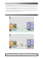
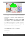
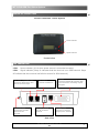
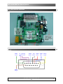
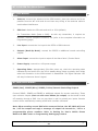
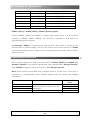
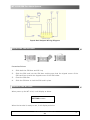
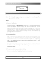
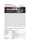
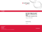
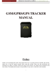
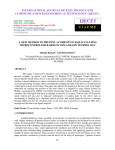
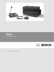
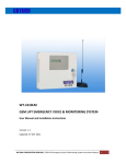
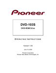
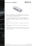
WT-1010
G
GS
SM
MF
Fo
orr A
Alla
arrm
mS
Sy
ysstte
em
m
User Manual
WT-1010 GSM For Alarm System
The WT-1010 GSM Terminal is a wireless communicator for alarm and fire panels that
uses the cell phone network (GSM) to transmit alarms and other panel event. The
module checks the status of the PSTN line and in case the PSTN line becomes
unavailable, the WT-1010 GSM emulate the line signal to the panel. At this time, the
panel will dial out using the GSM cell phone network to communicate with the receiver at
the monitoring station and transmit the alarms.
GENERAL OVERVIEW
WT-1010 – User Manual – Rev. 2.6
IDS
2
WT-1010 GSM For Alarm System
FEATURES
1. Panel compatibility - Allows any contact ID alarm panel to transmit alarms over GSM
using the GSM voice channel
2. Works over the GSM cell phone networks Units can be used wherever there is cell
phone coverage
3. Telephone line backup: WT-1010 give priority to the lowest cost network. WT-1010
uses the telephone line as the main transmission line and uses the GSM voice
channel as backup
4. The WT-1010 units can continuously watches if a Contact ID is directed towards the
security monitoring station through the wired or GSM network, and if either of the
preset report codes is noticed, it sends an appropriate SMS message with definable
text to a mobile phone numbers. Using this function, the owner can get instant SMS
messages not only of alarms but also every event of closing/opening.
5. Sends text messages to user programmable cell phone number (SMS): The WT1010 can be programmed to send a SMS to a programmable cell phone number to
notify the user that the PSTN line has been cut off or unavailable.
6. Low power consumption
- uses 30mA while in idle state and 260mA when
transmitting an alarm
7. Wall mounting enclosure available: The WT-1010 units can be installed inside alarm
panel or inside its own wall mount enclosure.
WT-1010 – User Manual – Rev. 2.6
IDS
3
WT-1010 GSM For Alarm System
SKETCH OF THE WT-1010
Point
The WT-1010 GSM –Alarm System
Power Indicator
Signal Indicator
Frontal view
LED INDICATORS
4oint
LED1 - Power indicator (it’s lit while power source is connected correctly)
LED1 - Signal indicator (Stays lit indicates that the terminal is on GSM network. Stays
off indicate that the terminal has failed to search for GSM network.)
TEL PORT 1 (ALARM INPUT)
Connect to Alarm Panel / also
function as Phone Input
ANTENNA PORT
Connect the provided
antenna to the
Terminal
TEL PORT 2
Connect to PSTN Line
ON/OFF SWITCH
Turn On or Off the
Terminal
OUTPUT
Connect the RS232 DB15 female cable
to the terminal for controlling outputs
and inputs
POWER PORT
Connect a 12V Power
Supply to the Terminal
Rear view
WT-1010 – User Manual – Rev. 2.6
IDS
4
WT-1010 GSM For Alarm System
WT-1010 WIRING DIAGRAM
Point
WT-1010 RS232 WIRING DIAGRAM (On WT-1010)
Point
ZONE4
(Green
)
For upgrading
firmware used
only
ZONE5
GND
ZONE1 ZONE2 ZONE3
(White) (Black) (Red)
(Blue) (Yellow
)
ZONE6
(Brown
)
WT-1010 – User Manual – Rev. 2.6
IDS
5
WT-1010 GSM For Alarm System
WT-1010 WIRING
Point
1.
Antenna: connect the antenna to the GSM module; place the antenna as far as
possible from the WT-1010 and do not leave any coiling of the antenna cable to
avoid radiant interference
2.
SIM Card: disable the PIN code and set it to 1234 (default)
For Transmitter Mode (Data or SMS): as with any transmitter, it requires an
identifier, receiver telephone numbers, etc (refer to the complete information on
Programming page)
3.
Line Input: connect the line input to the PSTN or ISDN network.
4.
Outputs (Back-Up Mode): connect the RS232 to additional remote controlling
outputs.
5.
Alarm Input: connect the input to output of the Alarm Panel / Control Panel.
6.
Power Supply: connect to a 12V power supply
7.
Operating State: Approximately 20s after power up, check the operating state
indicated by the Power LED: the LED is steady during power up phase, then blinks
when the connection to the GSM network is established. The Signal indicator LED
will stay lit whenever there is signal.
WT-1010 RS232 WIRING
Point
ZONE1(Red), ZONE2 (Blue), ZONE3 (Yellow) Remote Controlling Outputs
Connect ZONE1, ZONE2 and ZONE3 to additional outputs for remote controlling. These
open collector outputs (that can sink max 300ma per output) can be turned on and
off remotely through a SMS. You can use them to pull to ground your inputs. Remote
control will be reachable by sending a SMS with a certain command.
Note: When sending normal SMS with command below, the WT-1010 will turn
On / Off the output and reply a message of output has turned On / Off to a
programmable phone numbers. Refer to Setting for User’s Mobile Phone
Number & SMS Center on Programming Setting page below.
WT-1010 – User Manual – Rev. 2.6
IDS
6
WT-1010 GSM For Alarm System
Command
Description
Reply from WT-1010
AT+ZONE1=1
Turn on ZONE1
ZONE1 ON
AT+ZONE1=0
Turn off ZONE1
ZONE1 OFF
AT+ZONE2=1
Turn on ZONE2
ZONE2 ON
AT+ZONE2=0
Turn off ZONE2
ZONE2 OFF
AT+ZONE3=1
Turn on ZONE3
ZONE3 ON
AT+ZONE3=0
Turn off ZONE3
ZONE3 OFF
ZONE4 (Green), ZONE5 (White), ZONE6 (Brown) Inputs
Connect ZONE4, ZONE5 and ZONE6 to inputs panel, when there is a short-circuit
impulse on (ZONE4, ZONE5, ZONE6). the WT-1010 is possible to send SMS to a
programmable phone numbers.
For Example: ZONE4 is connected to a electrical door, when there is intruder or the
electrical door is opened illegally, WT-1010 will receive short-circuit impulse on ZONE4
and will automatically send a signal to the monitoring station and also send a SMS to
notify the owner.
PROGRAMMABLE ALARM SMS
User is able to change the content of alarm SMS for ZONE4, ZONE5 and ZONE6. For
Example: ZONE4 is connected to garage door and programmed as Garage Opened!,
when ZONE4 is triggered, owner will receive a SMS Garage Opened!
Note: When sending normal SMS with command below to the WT-1010, it will reply a
message to a programmable phone number indicate that the setting has changed
successfully.
Command
*IN1*Text Messages
*IN2*Text Messages
*IN3*Text Messages
*ALL*
Description
Allow user to change the content of
alarm message for inputs up to 19
characters
Erase all programmed text messages
WT-1010 – User Manual – Rev. 2.6
IDS
Reply from WT1010
Changed Done
Changed Done
Changed Done
Erased Done
7
WT-1010 GSM For Alarm System
Inputs And Outputs Wiring Diagram
INSTALLING THE SIM CARD
Point
Proceed as follows:
1.
Slide back the SIM door and lift it up
2.
Slide the SIM card into the SIM door making sure that the clipped corner of the
SIM card lines up with the clipped corner of the SIM holder
3.
Close the SIM door
4.
Slide the SIM door to lock the SIM card in place
POWER UP THE WT-1010
When power up the WT-1010, it will display as below
SETTING>>>>>
When the terminal is ready to use, it will display as below
WT-1010 – User Manual – Rev. 2.6
IDS
8
WT-1010 GSM For Alarm System
WT-1010
PROGRAMMING CODE SETTING
(Have To Enter Password Before Start Doing The Settings)
Note:
To start with programming, user must plug-in a normal single line
phone to TEL1 (Port 1)
Steps:
1. Password Verification
Pick up phone, press
**83211279#. If heard “du~~~” a continuous dialing tone,
means the Password entered correctly, and then will continue to go into
programming setting mode. User is able to change the settings now. If there is no
continuous “du~~~”, means the Password enter not correct. And it will not go into
programming setting mode to change the settings. User can hook-on and pick up
phone again to enter the Password.
2. Programming Code
Refer to the Programming Table below. After enter the Programming Code, if you
heard a busy tone follow by the dialing tone, it means wrong programming code. If
heard continuous “du~~~”, it means the successful set up for that programming
code. If just heard dialing tone, it means that the settings area are full or enter
wrong programming code.
During the setting for the programming code, user does not need to hook-on the
Phone. When user heard dialing tone after ONE setting means the user can continue
the following setting.
3. To Quit from the Programming Code Setting
In Hook-on mode or Press “hand-free” to quit from the setting.
WT-1010 – User Manual – Rev. 2.6
IDS
9
WT-1010 GSM For Alarm System
No.
1
Definition
Enter Password.
Go into
Programming
Setting
Program Code
**XXXXXXXX#
2
Setting for
Changing
Password
*6*XXXXXXXX#
3
Setting for
User’s Mobile
Phone number
*7*XXXXXXXXXXXX#
Erase User’s
Mobile Phone
number
*7*#
Dial this code will erase User’s
Mobile Phone number from WT1010 memory.
Setting for SMS
Center number
*8*XXXXXXXXXXXX#
After setting SMS Center
number, the terminal will be
able to send SMS.
For Example: SMS Center No.
+1234567890
Press *8**1234567890#
Erase SMS
Center number
*8*#
Dial this code will the erase
SMS Center number from WT1010 memory.
4
Description
After Password Verification, will
enter to the Programming
Setting Mode.
(Initial Password for factory
leaving is sets up as
“83211279”)
Before doing this setting, user
will need to use the default
password “83211279” to go
into Programming Setting Mode
to be able to use this
programming code to change
the password.
After programmed the mobile
phone number, the terminal is
able to send Alarm SMS to alert
the user notify that the PSTN
line of the Alarm System has
been cut off or unavailable.
4. Checking the GSM Service Status of W-1010
When the GSM link is completely lost by disconnection from the GSM network, the
alarm cannot be sent via GSM by WT-1010. User can always check the WT-1010
GSM Service by sending SMS to the WT-1010.
If the WT-1010 GSM Service is
available it will receive the message and will automatically reply the user.
If the
GSM Service failed, it will not reply the user. To check network status, send
AT010*# (normal SMS) to the WT-1010. If the GSM Service is available it will reply
“GSM OK”.
WT-1010 – User Manual – Rev. 2.6
IDS
10
WT-1010 GSM For Alarm System
VERIFICATIONS AND TESTS
Line Detect:
Simulate a line failure: disconnect the PSTN line from line port of WT-1010, and the
transmission of the PSTN fail alarm by WT-1010 will be sent. Check that the SMS has
been sent to the mobile recipient (if SMS transmission is programmed).
Reconnect the line: Check the transmission of PSTN line restore by the WT-1010 to
the GSM Data receiver of the Monitoring Station.
Simulate both GSM and PSTN failure: take out the SIM card from the WT-1010 and
disconnect the PSTN line, check that the voltage on GSM & PSTN failed Output that will
trigger the Alarm Siren.
TECHNICAL SPECIFICATIONS
General
•
SIM300 GSM/GPRS Module with 0dB antenna (2, 5m)
•
Optional accessory: remote antenna 10m cable 2dB gain, Marine Type with
FME/MMCX connector
•
CE Intrusion Product
Compatibility
•
Compatible in GSM Voice communications with any DTMF Control Panel ( including
speech synthesis Panels) and any landline alarm receiver
•
Compatible in SMS transmission to any mobile phone (text formatted SMS) and to
any SMS receiver, RD-id Type (Contact-ID formatted SMS)
•
Compatible for GSM Data Communications with the specific GSM Data receiver
Modex or Quasar
Power
•
Nominal voltage: 12V
Dimensions and Weight
•
L x W x H: 25 x 14 x 6 cm
•
Weight: 1.5Kgs
WT-1010 – User Manual – Rev. 2.6
IDS
11
WT-1010 GSM For Alarm System
Environmental Specifications
•
Environment temperature: 32° to 120° F
•
Relative humidity: Maximum 95%
Inputs and Outputs
•
Number of Outputs: 3
•
Output type: Open Collector
•
Max. current for inputs: 1A
WT-1010 – User Manual – Rev. 2.6
IDS
12