1
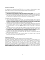
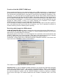
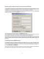
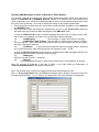
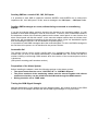
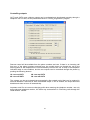
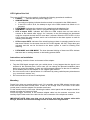
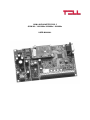
GSM-LINE ADAPTER PRO 5
GSM 900 / 1800 MHz / 850MHz / 1900MHz
USER MANUAL
Functions of the Unit
The purpose of the GSM-LINE ADAPTER PRO 3 is to interface to GSM network an alarm
system that can inform the security monitoring station through wired telephone line.
There are two main application areas of the unit:
• This adapter makes it possible to install alarm systems in places where there is no wired
PSTN line but it can be necessary to alarm the security monitoring station.
• By means of the GSM transmission, the adapter improves the reliability of alarm reporting in
cases when the wired alarm transmission does not work or fails (e.g. when the phone lines
are tampered or the telephone service is suspended due to technical reasons).
The adapter has some additional functions:
• The unit continuously watches if a CONTACT ID or ADEMCO Express report is directed
towards the security monitoring station through the wired or GSM network, and if either of
the preset report codes is noticed, it sends an appropriate SMS message with definable text
to one or two telephone numbers. Using this function, the owner can get instant SMS
messages not only of alarms but also of every event of closing/opening.
• The module can convert CONTACT-ID signals into SMS messages without being connected
to the monitoring station. To do this, enter 123456789 instead of the telephone number of
the monitoring station. In this case GSM-Line Pro 5 module will simulate the monitoring
station.
• The adapter can be set to forward the SMS messages arriving to the SIM Card to one or two
phone numbers. This function makes the use of non-subscription cards more secure, since
the owner/user can get the message about the actual balance to his own phone set.
• In connection with certain special devices (e.g. emergency telephone) a telephone number
can be set, which the module will automatically call when the receiver is picked up.
• Moreover, as a result of short circuit contact (IN1, IN2, IN3 inputs), it is possible to send an
SMS message with pre-set text.
• By means of OUT1 and OUT2 open collector outputs, it is possible to turn on and off
different devices remotely, through a telephone call.
Operation of the Unit
In case of incident, the alarm system initiates a call to the monitoring station.
The adapter continuously watches the existence and the functioning of a wired phone line. If
there is a functioning wired phone line, the unit directs the call to it; otherwise, if no wired line is
connected or the connected line does not work, the unit initiates the call through the GSM
network. Usually, an alarm system can be programmed to give a PGM output signal if it could
not access the monitoring station on several attempts (e.g. due to some fault in the telephone
exchange or sub-exchange). Connecting the mentioned output of the alarm system to the IN4
(DIRECT GSM) terminal of the adapter, it is possible to switch over to direct GSM transmission
even if a functioning wired phone line is connected to the adapter.
2
Preparation of the SIM Card
The SIM card necessary for the operation of the unit can be bought from any GSM service
provider.
(The adapter is independent of the actual GSM network).
For preparation and programming purposes, insert the SIM card into a mobile phone and
perform the following settings.
Before starting to set up the adapter, go through the following steps using the mobile phone:
• Make sure that the number of the SMS message centre is correctly set on the SIM card.
• Disable the PIN code request on the SIM card so that it shall not prompt for a PIN code on
turning the unit on.
• Delete the unnecessary SMS messages from the card.
Setting the Parameters of the Adapter
For the basic operation of the unit, it is not necessary to set any parameter on the SIM
card.
However, in order to reach the additional functions of the adapter as detailed in the following
sections, it is required to set certain parameters (e.g. the owner’s phone number, the number to
be dialed to access the external PSTN line, the texts of SMS messages, etc.)
These parameters can be entered by means of a computer through serial port, using the “Pro5
programmer” software which is freely downloadable from www.tell.hu website.
3
Function of the IN4 (DIRECT GSM) Input
Short-circuiting the IN4 input, the module switches over to GSM transmission, i.e. irrespective of
the existence of an analogue phone line, the adapter initiates the call through the GSM network.
This ensures the call transmission in case there is some fault in the telephone exchange or subexchange, i.e. if the wired phone line seemingly works but the alarm system cannot reach the
monitoring station through the wired PSTN network. Most alarm systems can be programmed to
give an output PGM signal after a certain number of unsuccessful attempts. If this signal arrives
to the IN4 input of the adapter, i.e. the wired line cannot be used, the unit will initiate the next call
through the GSM network. If there is no wired telephone line connected to the adapter,
additional care must be taken to connect the IN4 input as follows:
If it is necessary to manage incoming GSM calls, connect the IN4 input to the alarm system so
that it will short-circuit the input at the time of starting a call. This is important to prevent an
eventual incoming call from disturbing alarm reporting.
Receiving calls through the GSM network
GSM-LINE ADAPTER PRO 5 is able to manage the calls coming through the GSM network, i.e.
it can receive the incoming GSM calls by means of a simple analogue telephone set in places
where there is no wired phone line extension.
This function works only if there is no wired telephone line connected to the module and the IN4
(DIRECT GSM) input is not short-circuited. (This input of the module prevents the eventual
incoming calls from disturbing the outgoing calls initiated by the alarm system.)
Furthermore, incoming calls can be restricted according to telephone numbers. This function can
only be set in the “Call Filter” window of the software.
The duration of incoming calls can be restricted as well.
Important note: In case of telephone number restriction, do not enter the inland area changing
prefix before the telephone number, only the area code and telephone number. (The telephone
uses international format +3630… while displaying telephone numbers. The module compares
the received telephone number with the restricted telephone number by starting to compare
them from the last digits. The module handles the two numbers as identical even if +36 is left
out.
4
Setting a prefix number necessary to access external PSTN line
If the module is connected to a wired network where the dialing of a certain number (e.g. 9) is
necessary to access the external PSTN main line, this number must be given the adapter so that
it shall omit this number from the called number in case of initiating a GSM call.
To do this, enter the prefix that is necessary to access the external main line in the “Dial prefix
number used for outside line (#PREFIX)” field (e.g. 9).
As it can be seen on the picture there is an #ADDFIX parameter.
This is another prefix number, which the module inserts in front of the dialed number in all those
cases when the telephone call is performed through GSM network (GSM mode)
(For example, if the alarm system calls the wired telephone number without the area code, with
this parameter the area code can be added in case of calls through GSM network. In fact, this
function got vital importance because of the characteristics of some foreign wired telephone line
networks.)
Forwarding Incoming SMS Messages
It is possible to send the messages received by the SIM card to one or two other phone sets.
This makes safe the use of cheap non-subscription cards for security purposes. To do this, enter
the one or two phone numbers that you would like to receive the incoming SMS messages, in
the fields #SMSFW1 and #SMSFW2.
Note: When the module successfully forwarded the incoming SMS message, the message will
be deleted from the SIM card to make space for further incoming messages.
5
Sending SMS Messages In Case of Alarms or Other Events
The adapter continuously watches the calls initiated through the GSM network, and notices the
reports of CONTACT ID or ADEMCO Express formats. If it observes any of the given event
codes (maximum 10), it will send an SMS message to one or two telephone numbers with a text
that can be set by the user. This function needs the setting of the following parameters:
• Enter the phone numbers that you would like to send the SMS message to in the #USER1
and #USER2 fields.
• Enter the event codes that should be responded by the unit in the “Event Code” fields and
the texts belonging to them as SMS messages in the “SMS text” fields.
In case of CONTACT ID format, the SMS message must start with a 4-digit incident code,
then comes a ‘#’ character, and then you can enter the required message.
e.g.
1130#Burglary
(The first digit “1” means new event or opening)
or
3130#Restore after burglary (The first digit “3” means restore event or closing)
You can use the ’*’ joker character in the incident code, then the adapter accepts any digit in
the place of the joker character.
e.g.
313*#Alarm
In this case the module will send a message when it observes
any incident that has a code starting with the 313 sequence (3130 .. 3139).
In case of Ademco Express format you have to create similar SMS messages with the only
difference that the incident codes have only two digits.
e.g.
31#Burglary
Here you can also use the ’*’ character.
e.g.
3*#Alarm
(This message will be sent in case of any incident with a code between 30 and 39)
Note! By entering $ character in the text of SMS, in the sent SMS the information of
“event code/partition/zone” will appear instead of $.
Note: The module does not perceive signals sent through wired telephone lines.
Note.: In Pro5_programmer when an ADEMCO-Express code is entered, two zeros have to be
inserted before the code. (e.g. in case of 31=alarm, 0031 has to be entered in the program)
6
Sending SMS as a result of IN1, IN2, IN3 inputs
It is possible to send SMS to telephone numbers #USER1 and #USER2 due to short-circuit
impulse on IN1, IN2, IN3 inputs. For this, enter a message in the “IN1 input …. IN3 input” fields.
Sending SMS messages on event, without being connected to a monitoring
station
If you do not wish the alarm system’s signals to be directed to the monitoring station, it is still
possible to send SMS messages in case of some events. To do this, enter 123456789 instead of
the telephone number of the monitoring station into the alarm control panel. In case of alarm, the
alarm control panel will dial this number. In this case the adapter module does not initiate a real
phone call, but simulates the operation of the monitoring station (gives out handshake signals
and acknowledges CONTACT-ID and ADEMCO Express signals).
It is possible to send SMS messages about the received signals. For this, the SMS messages to
be sent have to be preset, as it is described in the previous section.
Automatic dial
This function can be used in certain, specific tasks (e.g. emergency calls). Enter the telephone
number that you wish to be dialed automatically in the #AUTO field. The module will dial the
number initiating a call through GSM network when the receiver of the connected phone device
is picked up.
(See picture at setting prefix numbers section.)
Preparation of the Alarm System
Before installing the adapter, check the following settings on the alarms system:
• The report format must be set to “CONTACT ID” or “ADEMCO Express”.
• The phone numbers of the monitoring station must be entered together with district
numbers so that they can be called from the SIM card through the GSM network.
• Dialing should be set to TONE mode
Testing the GSM Signal Strength
After the pushbutton on the adapter has been pressed shortly, the number of blinks of the GSM
MODE LED on the adapter indicates the actual GSM signal strength on a 5-point scale.
7
Controlling outputs
OUT1 and OUT2 open collector outputs can be activated and deactivated remotely through a
telephone call. For this, set the parameters below in “PRO5_programmer” program.
Remote control will be available from the phone numbers set here. If there is an incoming call
from any of the phone numbers entered here, the module does not forward the call to the
security panel or the telephone set, but automatically receives the call. A beep in the telephone
indicates ready to use condition, and the two outputs can be controlled through the phone by
pushing the following buttons:
1# - turn on OUT1
4# - turn off OUT1
2# - turn on OUT2
5# - turn off OUT2
The outputs can be set to deactivate automatically after certain period that can be entered in
seconds between 0 and 254 for each controllable output. If 255 is entered, the output becomes
bistable and does not turn off automatically.
Important note! Do not use area changing prefix when entering the telephone number, use only
area code and telephone number, the same way as described in “Receiving calls through the
GSM network” section.
8
LED Lights of the Unit
There are six LED lights on the module, indicating the following operational conditions:
• POWER:
Indicates that the power supply is on
• GSM NETWORK:
• Its continuous lighting indicates that the module is connected to the GSM network.
• If the LED is not lit at all, the attempt to sign in the GSM network has failed or is in
progress.
• PSTN MODE: indicates the existence of an operating wired telephone line
• GSM MODE: Indicates that a call is in progress through the GSM network.
• LED at output OUT3: Indicates that either the GSM module has not been able to
connect to the network after trying it for 3 minutes, or the field strength has decreased
under the required minimal level for more than 3 minutes. When the OUT3 LED is lit, the
OUT3 output also gets activated, and it can be fed back to the alarm system or used for
initiating local alarming.
•
LED at output OUT4: Indicates if the wired line has not been in operating mode for more
than three minutes. At the same time the OUT4 LED signals, the OUT output also gets
activated and this can be fed back to the alarm system or used for initiating local
alarming.
•
PSTN MODE and GSM MODE: The slow alternate blinking of these two LEDs indicate
that there are no settings loaded, or the loading process failed.
Instructions on Installation
Before installing, check the future environment of the adapter:
•
•
•
Test the GSM signal strength with your mobile phone. It may happen that the signal is not
sufficient in the selected place. In this case you can change the planned installation place
before you mount the adapter. If there are signal strength problems on the site of installation,
find a suitable place for the adapter or use a higher gain antenna.
Do not mount the unit in places where it is influenced by strong radiofrequency disturbances
(e.g. near electric motors, etc.).
Do not mount the unit in wet or humid places.
Mounting
Plastic fixing clips are supplied with the unit. If it is possible, put the GSM adapter into the same
metal case as the alarm control panel. If there is not enough room in the case of the alarm
control panel, install the adapter into another metal case.
Fix the antenna on top of the case. Mounting the alarm control panel and the adapter should be
started only after the antenna is fixed.
Screw the bigger connector of the antenna adapter cable into the antenna connector, then
carefully flip the other end of the cable into the mini connection of the telephone module.
IMPORTANT NOTE: Make sure that you do not force and drag the antenna cable while
fixing it, because if mechanical damage occurs it results loss of guarantee!
9
Connections
•
•
•
In case a wired telephone line exists, connect the ends of the phone line to the terminal
PSTN. The polarity is indifferent.
If the PSTN MODE LED lights, the line has been connected correctly.
(The signal of PSTN MODE LED is delayed)
Connect the phone line input of the alarm system to the “GSM-LINE” output of the GSM
adapter with the shortest cable possible. Here the polarity is also indifferent.
Use possibly shielded cable, and connect one end of the shielding to the ground potential
while leaving the other end free.
Installation of further connections (IN1, IN2, IN3, IN4, OUT1, OUT2, OUT3, OUT4) can be
done if requested, see at functions.
Setting Up
•
•
•
•
Insert the SIM card in its case, if it is necessary, in programmed state. PIN code request
should be disabled.
The caller number identification function must be enabled by the GSM service provider on
the SIM card (a few types of SIM cards do not have this function enabled by default).
Make sure that the connections correspond to the above instructions.
Apply supply voltage to the unit (9-24V). Make sure that the power supply current is sufficient
for the load when the alarm system and the adapter are working together.
The quiescent current of the adapter is 200 mA, but the it may increase to 500 mA during
communication.
Setting by means of the computer
All necessary parameters for the operation of the module can be done by means of a PC.
Download “Pro5_programmer” from www.tell.hu website.
For programming, it is necessary to have a 9-pole serial connecting cable (serial mouse
expanding cable)
Connect the module to the PC with the serial cable.
Start the program and choose the serial port where the module is connected.
With this program not only settings, but the operation of the module can be traced as well.
The settings take effect only after being downloaded in the module by pressing the “Write
parameters to module” button.
Further notes
•
•
•
The adapter accepts both Tone (DTMF) and Pulse dials.
The adapter does not know in advance the length of the number to be dialed, therefore
do not wait too long before entering the next digit, because if you do so the module might
suppose that dialing has already finished. (The adapter expects at least 7 digits and does
not start dialing until they are entered. It starts calling a number of 7 and 10 digits after a
5 second pause. In case of 11 or more digits, the adapter starts dialing after a 2 second
pause.)
If an alarm system is connected, the above mentioned does not mean a problem
because of the quick automatic dialing, this problem has to be considered only in case of
manual dialing.
Telephone numbers shorter than 7 digits can be dialed by entering # after the number.
Enabling and disabling telephone number display
By entering *31# before the telephone number, telephone number display is enabled on the
called person’s telephone, and by entering #31# this function is disabled.
10
A
B
C
E
D
F
PC RS232
G
I
M
J
H
9-24V DC
K
L
Antenna
Metal housing
Antenna adapter cable
GSM-Line Adapter Pro 5
Antenna connection
SIM card case
GSM module
Supply voltage input terminals 9-24V DC
RS232 connector for the communication with PC
Connectors :
- GSM-LINE (2 wire): Generated telephone line/ PSTN line connector towards the alarm
system
- PSTN
(2 wire): Connector for incoming wired telephone line
- IN1 (contact input for SMS sending)
- IN2 (contact input for SMS sending)
- IN3 (contact input for SMS sending)
- IN4 (DIRECT GSM function)
- COM common point (ground) for IN1… IN4 inputs
- OUT1 : output that can be remote controlled through a telephone call (open collector)
- OUT2 : output that can be remote controlled through a telephone call (open collector)
- OUT3 : output for signaling the failure of GSM line that lasts longer than 3 minutes
(open collector)
- OUT4 : output for signaling the failure of wired line that lasts longer than 3 minutes
(open collector)
K – Incoming wired telephone line (PSTN)
L – Telephone line input of alarm system
M – Pushbutton
A–
B–
C–
D–
E–
F–
G–
H–
I–
J–
11
Technical specification:
Supply voltage:
9-24V DC
Maximum current consumption:
500 mA
Operating temperature:
between -10 ºC and + 60 ºC
Transmission frequency:
GSM 900 MHz / 1800 MHz / 850MHz / 1900MHz
Dimensions:
127x86x27 mm
Net weight:
70 g
Gross weight (packed):
400 g
• Outputs OUT1, OUT2, OUT4, OUT4:
o open collector outputs
o output current
max 100mA
o allowed smallest load: min.150 Ohm
o it is necessary to use protecting diodes in case of using relays * (e.g. 1N4004)
o It is forbidden to connect it on supply voltage without loading!
12V
*
Min 150 Ohm
e.g. relay
Error output
Generated telephone line specification
Line voltage:
Line current:
Line impedance:
Ringing voltage:
Dial tone:
48 V
25 mA
600 Ohm
±72 V (25 Hz)
400 Hz
Contents of the package
-
GSM LINE ADAPTER PRO 5
Antenna adapter cable (MMCX-FME)
GSM 900 MHz / PCN 1800 MHz antenna
4 pieces of fixing supports
User’s Manual, Warranty card
Summary table of parameters:
#SMSFW1
#SMSFW2
#PREFIX
#USER1
#USER2
#ADDFIX
#AUTO
Phone numbers necessary for forwarding the incoming SMS messages
Prefix number necessary to access the external PSTN line
Phone numbers that get SMS messages from the module in case of observing
given incident codes
Prefix number that should be added to telephone numbers called in GSM mode
Phone number for autodial function
12