1
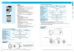
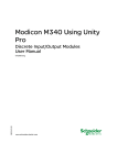
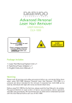
Brake Unit
Contacting type
• Features
Outline of Brake Unit
<SD type>
<EX type>
Product designation
EX type
1
02
Voltage
Type
1. Can be controlled using electrical signal.
Electrical signal can be used for “run”, “quick stop” and
“coast to stop” control of motors.
2. Operation time of the electric brake is adjustable.
Operation time is set to a suitable value within the range
from 0.1 to 2 sec
3. “Run” and “Instantaneous stop” lamps are provided.
Index
SD type
• Separate type
DZ9
Options
1. Compact 8P plug-in configuration.
2. Can be used in combination with other commercially
available SSR (contactless relay).
These combinations enable the use of electrical signals
for “run” and “quick stop” control of motors.
3. The electric brake operates for approx. 0.5 sec.
• These units are electric brakes that can stop motor immediately.
• These brake units are divided into the contact (separate) type and contactless (48 mm sq.(1.89 inch sq.)) type.
• Separate type brake units can be used with 3-phase motor.
• The contactless 48 mm sq.(1.89 inch sq.) type brake units can be used with induction motor, reversible motor and
electromagnetic brake motor.
Brake Unit
• These brake units are electric brakes used to
instantaneously stop motors.
• These electric brakes have longer life expectancy and
can perform inching operation.
Speed controller
Brake Unit Overview
SD type
EX type
1: Single-phase 100 VAC
2: Single-phase 200 VAC
3: 3-phase 200 VAC
• Names and functions
• Braking time control
Adjusts the time up to 2 sec (standard).
Since longer braking current increases
motor temperature, the shortest time
necessary to stop the motor is the
recommended setting.
Separate type brake unit
• Sq.48 mm contactless brake unit
MODEL
DZ9102
VOLTAGE AC100V
• Brake lamp
DVMB
48
1
L
Brake unit
Size
Output
Voltage
48 mm sq.
(1.89 inch sq.)
L : 100 V
Y : 200 V
Lights in red while the braking current is
flowing.
• Run lamp
Lights in green while the motor is running.
PHASE
1ø
FREO.
50/60Hz
CURRENT
AC100V
3Amax
DZ9113
EX type
SD type
1: For induction motor
2: For reversible motor
3: For electromagnetic brake motor
* Please read your User's manual carefully so that you will understand the operation and safety precautions before attempting to operate the system.
C-46
C-47
Contacting type
• Models and applicable motors
SD type
Brake Unit
Contacting SD type
The thick continuous lines in the circuit diagram below represent main circuit. Use conductor of approx. 0.75 mm2.
The thin continuous lines represent signal circuit. Use conductor of size approx. 0.3 mm2.
EX type
Speed controller
Brake Unit
• DZ9102 and DZ9202 fundamental electrical wiring diagram (induction motor)
DZ9102
DZ9202
DZ9302
DZ9113
DZ9213
Induction motor
Reversible motor
Rated voltage
input
SW3
3-phase 200 V
CW
RUN
BRAKE
White
C1
DZ9202
DZ9302
Item
SW2
RUN
BRAKE
RUN
BRAKE
SW3
Electric
brake
RUN
BRAKE
RUN
BRAKE
Motor
T1
DZ9213
DZ9113
Single-phase 100 VAC Single-phase 200 VAC
50/60 Hz
Power frequency
50/60 Hz
Operation current 3 A
Permissible current
Operation current 3 A
Applicable motor
3 to 90 W
Applicable motor
3 to 90 W
Braking method
Feeds electric braking current for a specified time
Braking method
Feeds electric braking current for a specified time
R2
7
8
Electric braking time
0.5 sec (typ)
Electric braking time
Variable up to 2 sec (typ)
Operating temperature
–10 to 50˚C
Operating temperature
–10 to 50˚C
Storage temperature
–10 to 60˚C
Storage temperature
–10 to 60˚C
Gray
SW1 100 V supply system
Black
SW2 200 V supply system
SW3
R2
Capacitor
Pin No.
• When wired as shown above, the motor turns clockwise when viewed from the shaft end. To turn it
counterclockwise, exchange brown and gray leads.
[Notes]
1. Electric braking system has no holding torque.
2. For application requiring holding force, use Panasonic electromagnetic brake motor.
3. When braking a load with excessively large inertia, related issues are strength and life of motor shaft and gear. For these subjects,
consult us.
4. When using motor other than compact geared motor, consult us.
R2
R1+C1
DVOP008 (option)
Motor
25 W or smaller 40 W or larger
100 V supply system
0Ω
30 Ω (approx. 100 W)
200 V supply system
0Ω
100 Ω (approx. 100 W)
Control signal
SD type
Unit: mm (inch)
EX type
Unit: mm (inch)
• When using power relay
• When using contactless relay (SSR)
RY3 HC relay (Panasonic Electric Works Co.,Ltd.), or equivalent
14.2(0.56)
50(1.97)
14.2(0.56)
36(1.42)
59(2.32)
93.5(3.68)
59(2.32)
50(1.97)
61(2.4)
36(1.42)
NFB
SW1
1
2
Rated voltage
input
R1
6
C1
R2
7
8
Gray
Motor
Vcc
Capacitor
RUN
5
4
33±3.0(1.3±0.12)
0.5(0.02)
8
6
2
1
3
7
ø29(ø1.14)
12.0(0.47)
5
39±0.1
(1.54±0.004)
48.4(1.9)
ø3.8(ø0.15)
3.0(0.12)
t0.8(0.031)
48±2(1.89±0.08)
(2.2(0.087))
10.5 –1.5
(0.41–0.059)
8.0(0.31)
6.0
(0.24)
4(0.16)
14.0(0.55)
20.8(0.82)
0.8
(0.03) 10.5
(0.41)
33(1.3)
• External resistor for braking (for DZ9302 only)
5.2
(0.02)
(ø2.5(ø0.01))
9.0(0.35)
0.6(0.02)
* Please read your User's manual carefully so that you will understand the operation and safety precautions before attempting to operate the system.
Pin No.
SSR
INPUT
CW
White
LOAD
Brown
R2
7
4
5
Vo
• Socket (common to SD and EX)
Connection for
DZ9202
Gray
Motor
Black
8
R2
Ry3
Unit: mm (inch)
Rated voltage
input
6
Brown
Black
NFB
SW1
1
2
White
R5
Accessories
SSR AQ2017 (Panasonic Electric Works Co.,Ltd.), or equivalent
CW
Connection for
DZ9202
Ry3
4
6(0.24)
5 A or more at 250 VAC
DC10V 10mA
[Notes]
1. When SW2 and SW3 are switched from RUN to BRAKE, electric brake is applied for approx. 0.5 sec (T1) causing the
motor to stop quickly.
2. Both SW2 and SW3 should be switched from RUN to BRAKE at the same time.
3. The wattage of R2 depends on frequency of start and stop operations. First check the power dissipation.
• Outline drawing
C-48
5 A or more at 125 VAC
Index
Power frequency
Permissible current
3.2(0.13)
T1
6
Part No.
Rated voltage
Braking
Run
ON
Options
DZ9102
Single-phase 100 VAC Single-phase 200 VAC 3-phase 200 VAC
Rated voltage
RUN
Connection for DZ9202
<EX type>
Part No.
R1
Brown
• Specification
Item
SW2
BRAKE
3
<SD type>
Braking
Run
SW1
Single-phase 200 V
3-phase motor
NFB
SW1
1
2
Single-phase 100 V
Brake Unit
Rated voltage
R5
R2
Vcc
Capacitor
If
RUN
Vo
BRAKE
BRAKE
Pin No.
[Notes]
1. Use 0 W R5 when Vcc is below 6 VDC.
When Vcc is 6 VDC or higher, determine the value of R5 according
to the equation shown below.
Ripple of Vcc should be 5% or below. (Internal resistance 220 Ω)
• Resistance of R5 R5 = Vcc – 6 V at If = 15 to 20 mA
If
Run
SW1
• Example Vcc = 24 V If = 20 mA
24 – 6
R5 =
= 900 Ω = 1 kΩ
20 x 10–3
Vo
RUN
Braking
Braking
Run
ON
BRAKE
RUN
BRAKE
2. Also refer to SSR handling precaution (see contactless relay catalog).
* Please read your User's manual carefully so that you will understand the operation and safety precautions before attempting to operate the system.
C-49
Contacting SD type
The thick continuous lines in the circuit diagram below represent main circuit. Use conductor of approx. 0.75 mm2.
The thin continuous lines represent signal circuit. Use conductor of size approx. 0.3 mm2.
The thick continuous lines in the circuit diagram below represent main circuit. Use conductor of approx. 0.75 mm2.
The thin continuous lines represent signal circuit. Use conductor of size approx. 0.3 mm2.
• DZ9102 and DZ9202 standard electrical diagram (reversible motor)
• DZ9302 fundamental electrical wiring diagram (3-phase motor)
SW3
RUN
BRAKE
CW
R1
SW2
SW4
RUN
3
6
RUN
BRAKE
C1
C1
White
RUN
8
RUN
Gray
RUN
BRAKE
Black
SW3
RUN
RUN
RUN
SW5
CW
R1
Ry5
6
NFB
SW3
Ry4 Ry5
DV0P008 (option)
Motor
25 W or smaller
40 W or larger
100 V supply system
0Ω
30 Ω (approx. 100 W)
200 V supply system
0Ω
100 Ω (approx. 100 W)
4
5
Pin No.
R6
If
Ry4
4
Vcc
5
Ry5
Vocw
Vocw
RUN
LOAD
White
Gray
R2
Black
Capacitor
R5
NFB
SSR
Black
R2
Vcc
Motor
R6
R5
SW3
C1
Ry2
Ry1
Ry2
White
Braking
R1+C1
SW1
SW2
SW4 SW5
RUN
BRAKE
RUN
SW3
RUN
BRAKE
RUN
Motor
Black
Ry3 Ry2 Ry1
C1
Gray
RY1, RY2
Run
ON
CW
R1
SW1, SW6 AC250 V 10 A min.
Accessory
Braking
3ø
AC200V
Pin No.
DC10 V 10 mA
DV0P008 (option)
R4
S
T
R
BRAKE
7
R4
RY3
BRAKE
Relay HP/HG (Panasonic Electric Works
Co.,Ltd.) or equivalent
DV0P008 (option)
Accessory
Twin contact or Au-clad contact relay
Braking
Run
SW1
Braking
Run
ON
T1
[Notes]
1. When SW2, SW3 and SW4 are switched from RUN to
BRAKE, electric brake is applied for approx. 0.5 sec (T1)
causing the motor to stop quickly.
2. Do not place these switches to RUN position while the
electric braking is applied (T1).
3. A massive amount of current will flow through SW2, SW4
and SW5. Use a disconnecting device (switch or relay)
rated at 10 A or more. When using a relay, use HP/HG
(Panasonic Electric Works Co.,Ltd.) or equivalent.
Capacitor
SW6
RUN
Ry2
ON
ON
Ry3
ON
ON
Ry1
Electric
brake
BRAKE
RUN
BRAKE
ON
ON
T1
T1
[Notes]
Ry1 and Ry2 should be interlocked to avoid
simultaneous “ON”.
Control signal
Vocw
Pin No.
• When using power relay
Voccw
RUN
BRAKE
BRAKE
SSR
R6
RY1 Relay HP/HG (Panasonic Electric Works Co.,Ltd.) or equivalent
NFB
SW1
AQP107 (Panasonic Electric Works
Co.,Ltd.), or equivalent
1
2
R4
6
R1
C1
Ry1
SW1
Vocw
Voccw
Electric
brake
RUN
Braking
Run
ON
White
BRAKE
BRAKE
RUN
T1
Gray
7
4
RUN
BRAKE
T1
R5
Vcc
Ry1
If
5
RUN
BRAKE
RUN
BRAKE
Motor
[Notes]
1. Use 0 Ω R5 when Vcc is below 6 VDC.
When Vcc is 6 VDC or higher, determine the value of R5
according to the equation shown below.
Ripple of Vcc should be 5% or below.
(Internal resistance 220 Ω)
• Resistance of R5
RUN
Vo
Pin No.
Vo
C1
Black
Braking
SW1
Braking
Run
ON
CW
R1
C1
Braking
Run
3ø
AC200V
R1
Ry1
10 Ω
Run
S
T
R
Ry1
* Please read your User's manual carefully so that you will understand the operation and safety precautions before attempting to operate the system.
C-50
Ry2
C1
R1
AC250 V 10 A min.
R1+C1
If
[Notes]
1. Use 0 Ω R5 when Vcc is below 6 VDC.
When Vcc is 6 VDC or higher, determine the value of R5 according
to the equation shown in description for induction motor.
Ripple of Vcc should be 5% or below. (Internal resistance 220 Ω)
2. Ry4 and Ry5 should be relay or electromagnetic contactor with the
rated voltage two or more times the power supply voltage and the
rated current 3 A or more.
3. Do not place Vocw and Voccw in RUN at the same time.
4. Be sure to use resistor R6 to protect relay, SSR and capacitor.
Current will flow through R6 - 2 A 90 W; 1.7 A 60 W; 1 A 40 W; 0.6
A 25 W; 0.4 A 15 W.
5. Also refer to SSR handling precaution (see contactless relay
catalog).
R4
Ry1
Run
AC100V
LOAD INPUT
SW6
RUN
R1
Ry2
SW4, SW5
R1+C1
1
2
7
8
Gray
R2
8
7
DC10 V 10 mA
SW1
INPUT
Ry1
Gray
SW1, SW2
SSR
Motor
7
3
6
C1
T1
• When using contactless relay (SSR)
(Cannot be used for DZ9202)
White
R2
Motor
Black
SW4, SW5 200 V supply system 5 A or more at 250 VAC
C1
C1
BRAKE
SW1, SW2 100 V supply system 5 A or more at 125 VAC
R1
Ry4
RUN
Ry3
White
T1
Rated voltage
input
Connection for
DZ9202
C1
NFB
SW1
1
2
Electric
brake
• When using power relay
SW1
R4
CW
R1
RUN
Pin No.
Control signal
1
2
C1 BRAKE
Index
CCW
T1
R2
SW4
• For application using inching motion frequently
If SW2 and SW5 emit long sparks, use of the
following circuit is recommended.
CW
Electric
brake
[Notes]
1. When SW2 (SW4) and SW3 are switched from RUN to
BRAKE, electric brake is applied for approx. 0.5 sec (T1)
causing the motor to stop quickly.
2. Never place both SW2 and SW4 in RUN position at the
same time.
3. Never select RUN while electric brake is applied (T1).
4. When using DZ9202, do not operate SW5 while the
electric brake is being applied (T1).
5. The wattage of R2 should be determined based on
frequency of start and stop operations. First check the
power dissipation.
R1
RUN
R1
BRAKE
Capacitor
SW2
BRAKE
3
6
SW4
R2
Pin No.
RUN
Braking
BRAKE
3ø
AC200V
SW3
BRAKE
SW5
SW2
7
Run
ON
SW1
CCW
R2
Braking
Run
Motor
SW5
CW
Clockwise
T
R
CCW Counterclockwise
R1
S
1
2
Options
BRAKE
Connection for
DZ9202
CW
NFB
SW1
Rotating direction viewed
from shaft end
Rated voltage
input
Brake Unit
NFB
SW1
1
2
Speed controller
Brake Unit
BRAKE
R5 = Vcc – 6 V at If = 15 to 20 mA
If
• Example Vcc = 24 V If = 20 mA
24 – 6
R5 =
= 900 Ω = 1 kΩ
20 x 10–3
* Please read your User's manual carefully so that you will understand the operation and safety precautions before attempting to operate the system.
C-51
Contacting EX type
The thick continuous lines in the circuit diagram below represent main circuit. Use conductor of approx. 0.75 mm2.
The thin continuous lines represent signal circuit. Use conductor of size approx. 0.3 mm2.
Brake Unit
Speed controller
Brake Unit
Contacting EX type
• Stopping coasting DZ9113/DZ9213
• Coast stopping circuit wiring diagram
• Operation
• DZ9113/DZ9213 fundamental electrical wiring diagram (unidirectional rotation and braking)
Input rated
voltage
2
CW
R7
• When wired as shown left, the motor turns
clockwise when viewed from the shaft end.
To turn it counterclockwise, exchange
brown and gray leads.
If
5
R7
6
Vo
If
V1
Vo
RUN
V1
FREE RUN
Operation
RUN
Brake Unit
NFB
SW1
3
RUN
BRAKE
STOP
RUN
BRAKE
STOP
White
8
R2
Gray
R2
Black
5 A or more at 125 VAC
200 V supply system
5 A or more at 250 VAC
Motor
Motor
R2
Connection for DZ9113
1
100 V supply system
25 W or smaller
R7
5
R7
If
RUN
If
6
Vo
BRAKE
Pin No.
100 V supply system
0Ω
30 Ω (approx. 100 W)
200 V supply system
0Ω
100 Ω (approx. 100 W)
[Notes]
1. Use 0 Ω R5 when Vcc is below 6 VDC.
When Vcc is 6 VDC or higher, determine the value of R5
according to the equation shown below.
Ripple of Vcc should be 5% or below. (Internal resistance 90 Ω)
• Resistance of R7
Braking
Run
SW1
ON
Vo
BRAKE
RUN
2. The wattage of R2 depends on frequency of start and stop
operations. First check the power dissipation.
BRAKE
RUN
R7 = Vcc(MIN) – 6 V at If = 32 to 45 mA
If
• Example: Vcc (MIN) = 12 V If = 40 mA
12 – 6
R7 =
= 150 Ω
40 x 10–3
Braking
Run
• DZ9113 application wiring diagram (normal/reverse rotation and braking)
SW1
Motor
Single-phase 100 V
Reversible motor
SSR
AQP107 (Panasonic Electric Works Co.,Ltd.)
or equivalent
SSR
INPUT
White
R2
7
8
R6
Gray
R6
R2
4
Vcc
Black
Capacitor
Voccw
Vocw
RUN
BRAKE
RUN
1
R7 I f
6
Pin No.
Run
Braking
Run
ON
SW1
Vocw
Voccw
Electric
brake
Braking
BRAKE
RUN
BRAKE
RUN
T1
• Contactless signal input driving
• Wattage of fixed resistor (R2)
300
• These are internal equivalent circuits
that may be used for contactless signal
driving devices such as TTL and MOSIC.
Electric power
resistor
250
300 W
4
10 Ω
220 Ω
RUN
BRAKE
[Notes]
1. For information on R2, SW1, etc., not found in this
figure, refer to the fundamental electrical diagram
shown above.
2. For information on the SSR, refer to the related
documents available from the contactless relay
manufacturer.
3. The rated voltage of SSR should be 2 times or more
the power supply voltage and the surge rating should
be 100 A or more.
4. Be sure to use resistor R6 to protect SSR and
capacitor.
Current will flow through R6 - 2 A 90 W; 0.7 A 60 W; 1
A 40 W; 0.6 A 25 W; 0.4 A 15 W. Determine the
wattage by first checking the heat dissipation.
5. Never turn on the motor while the electric braking is
operating (T1).
6. Do not place Vocw and Voccw in RUN position at the
same time.
7. For Vcc and R7, refer to “Unidirectional rotation and
braking” above.
T1
* Please read your User's manual carefully so that you will understand the operation and safety precautions before attempting to operate the system.
C-52
SD type, EX type
The thick continuous lines in the circuit diagram below represent main circuit. Use conductor of approx. 0.75 mm2.
The thin continuous lines represent signal circuit. Use conductor of size approx. 0.3 mm2.
Motor
R7 I f
5
Brake Unit
NFB
AC100V
LOAD
1. Turning on and off of input voltage V1 on pin 6 causes coasting and braking, respectively.
2. For the resistance value of R7, refer to basic electric wiring diagram (negative direction rotation and braking) of DZ9113/DZ9213.
3. For the remaining wiring connections, refer to respective electric wiring diagrams.
5
SD type
Required resistor wattage (W)
3
2
: Electric braking applied
[Notes]
Index
Vcc
Brake
Free run
40 W or larger
Capacitor
4
Pin No.
200
200 W
150
150 W
With 200 VAC power supply
R2 = 100 W (half-wave of 200 VAC)
1 sec ON,
sec OFF
120 W
100
100 W
80 W
60 W
50
With 100 VAC power supply
4
Control circuit
7
SW1
Brown
Options
Connection for DZ9213
LED
150 Ω 220 Ω
40 W
12
14
16
18
20
OFF period (sec)
5
6
EX type
R2 = 30 W (half-wave of 100 VAC)
1 sec ON,
sec OFF
0
0
2
4
6
8 10
[Notes]
The curves shown above are required wattage of electric power
resistor R2 to maintain the surface temperature of it at 200˚C or
below when it is driven with WR (average on/off cycle power)
and 35% load factor.
Load factor = 35%
ON duration (braking time) = 1 sec
(fixed)
1. When 100 VAC supply WR = 476/(Toff + 1)
2. When 200 VAC supply WR = 571/(Toff + 1)
Example: 10 sec run; 5 sec stop; 1 sec braking; under 100 VAC
WR = 476 / [(10 + 5 + 1) + 1] = 31.7 W
* Please read your User's manual carefully so that you will understand the operation and safety precautions before attempting to operate the system.
C-53