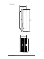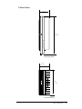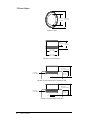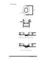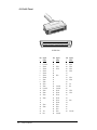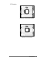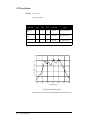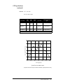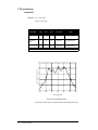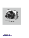
1
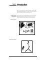
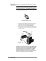
,
SenSys
™
User Manual
SenSys™ User Manual
© Copyright 1998
Photometrics Ltd.
3440 East Britannia Drive
Tucson, Arizona 85706
TEL: 520/889–9933
FAX: 520/295-0299
All rights reserved. No part of this publication may be reproduced by any means without the written
permission of Photometrics Ltd.
Printed in the United States of America.
US Patents 5,594,520 and 5,393,931
Metachrome and PVCAM are registered trademarks of Photometrics Ltd.
CAMTEST, PPD, and SenSys are trademarks of Photometrics Ltd.
Nikon is a registered trademark of Nikon Corporation.
Other brand and product names are the trademarks or registered trademarks of their respective owners and
manufacturers.
The information in this publication is believed to be accurate as of the publication release date. However,
Photometrics Ltd. does not assume any responsibility for any consequences including any damages resulting
from the use thereof. The information contained herein is subject to change without notice. Revision of this
publication may be issued to incorporate such change.
Warning: This is a Class A product. In a domestic environment this product may cause radio interference in which case
the user may be required to take adequate measures.
Camera System Warranty (excluding software)
Photometrics Ltd. warrants that its products are free of defects in material and workmanship.
The period over which Photometrics’ products are warranted is twelve (12) months from the date of shipment
listed on the packing slip shipped with the equipment. Photometrics will repair or replace the product if it is
found to be defective within the warranty period.
Photometrics must be notified in writing of the defect within the warranty period. The affected product should
be returned to Photometrics within thirty (30) days after discovery of such defect. Shipment should not be made
without prior authorization by Photometrics.
When products are returned to Photometrics for warranty service, the buyer shall prepay shipping charges to
Photometrics and Photometrics shall pay shipping charges to return the product to the buyer. The buyer shall
pay all shipping charges, duties, and taxes for products returned to Photometrics from outside the U.S.A.
This warranty does not apply to defects resulting from improper or inadequate maintenance by the buyer,
buyer-supplied software or interfacing, unauthorized modification or misuse, or improper site preparation or
maintenance.
Photometrics’ liability shall not exceed the cost of repair or replacement of the defective equipment.
This warranty becomes void if the user attempts to repair or modify the product without the written consent of
Photometrics. Except for removing the shutter cover, this warranty is voided if the user opens the camera head.
Metachrome® II Warranty
Photometrics Ltd. warrants that the Metachrome II coating will maintain 95% of initial quantum efficiency
without the need to pre-flash. This warranty is not affected by high UV exposure levels.
The period over which Metachrome II coating is warranted is twenty-four (24) months from the date of
shipment listed on the packing slip shipped with the equipment. Photometrics will recoat the CCD at no cost if
quantum efficiency drops below 95% of initial performance within the warranty period.
Photometrics must be notified in writing of the defect within the warranty period. The affected camera system
should be returned to Photometrics within thirty (30) days after discovery of such defect. Shipment should not
be made without prior authorization by Photometrics.
The buyer shall prepay shipping charges to Photometrics and Photometrics shall pay shipping charges to return
the product to the buyer for products returned to Photometrics for warranty service. The buyer shall pay all
shipping charges, duties, and taxes for products returned to Photometrics from outside the U.S.A.
This warranty does not apply if reduced quantum efficiency due to damage to the CCD or Metachrome II from
unauthorized modification or use of the camera system.
Photometrics’ liability shall not exceed the cost of repair or replacement of the defective equipment.
This warranty becomes void if the user attempts to repair or modify the product without the written consent of
Photometrics. This warranty is voided if the user opens the camera head.
SenSys Sealed Chamber Integrity Warranty
Photometrics Ltd. warrants the SenSys sealed chamber integrity for a period of twenty-four (24) months.
The warranty period is from the date of shipment listed on the packing slip shipped with the equipment.
Photometrics will repair or replace the camera system if it fails to maintain the sealed chamber integrity with
proper use within the warranty period.
Photometrics must be notified in writing of the defect within the warranty period. The affected camera system
should be returned to Photometrics within thirty (30) days after discovery of such defect. Shipment should not
be made without prior authorization by Photometrics.
The buyer shall prepay shipping charges to Photometrics and Photometrics shall pay shipping charges to return
the product to the buyer for products returned to Photometrics for warranty service. The buyer shall pay all
shipping charges, duties, and taxes for products returned to Photometrics from outside the U.S.A.
This warranty does not apply to defects resulting from improper or inadequate maintenance by the buyer,
unauthorized modification or misuse, or improper site preparation or maintenance.
Photometrics’ liability shall not exceed the cost of repair or replacement of the defective equipment.
This warranty becomes void if the user attempts to repair or modify the product without the written consent of
Photometrics. This warranty is voided if the user opens the camera head.
Declaration of Conformity
Photometrics, Ltd. declares that the equipment described in this document is in conformance
with the requirements of the European Council Directives, listed below:
89/336/EEC
EMC Directive
93/68/EEC
EMC Directive
73/23/EEC
Low Voltage Directive
on the approximation of the laws of Member States relating to Electromagnetic Compatibility and
Product Safety.
This declaration is based upon compliance of the product to the following standards:
EN 55022-A, CISPR 22
EN 50082-1, IEC 801
EN 60950, IEC 950
RF Emissions Control
Immunity to Electromagnetic Disturbances
Product Safety
Product Description: CCD Camera System
Model: SenSys Camera System
Authorized Signature
Wilhelm Pfanhauser
Photometrics, Ltd.
Sollner Str. 61
D-81479 München
Germany
Date
11/16/95
Table of Contents
Chapter 1. Introduction
SenSys System Components .................................................................................. 1
Standard Components....................................................................................... 1
Optional System Hardware .............................................................................. 1
About this Manual ................................................................................................... 2
Environmental Requirements ................................................................................ 2
Storage Requirements ............................................................................................. 2
Precautions................................................................................................................ 2
Repairs....................................................................................................................... 3
Cleaning .................................................................................................................... 3
Photometrics Customer Service............................................................................. 3
Chapter 2. Hardware Installation
Connecting Mount Adapters, Tripod Mounts, and Other Instruments .......... 5
Connecting the AIA Cable...................................................................................... 5
Connecting the Power Brick................................................................................... 6
Chapter 3. Configuration Options
Lens Mount Adapters ............................................................................................. 7
C-Mount Assembly............................................................................................ 8
F-Mount Assembly ............................................................................................ 9
Tripod Camera Stand ............................................................................................ 10
Chapter 4. Component Descriptions
CCD.......................................................................................................................... 11
MPP .................................................................................................................... 11
Metachrome II................................................................................................... 12
Certificate of Calibration................................................................................. 12
Window................................................................................................................... 12
CCD Chamber ........................................................................................................ 12
Thermoelectric Cooler........................................................................................... 12
Shutter ..................................................................................................................... 12
Electronics ............................................................................................................... 13
Input/Output Trigger Port .................................................................................. 13
AIA Port .................................................................................................................. 14
Power Port .............................................................................................................. 14
Status Lights ........................................................................................................... 14
Power Brick............................................................................................................. 15
Mount Adapters..................................................................................................... 16
C-Mount ............................................................................................................ 17
F-Mount ............................................................................................................. 17
Lenses ...................................................................................................................... 17
Tripod Camera Stand ............................................................................................ 17
Chapter 5. Troubleshooting
Green Light on Camera Does Not Illuminate.................................................... 19
Image is Fuzzy........................................................................................................ 19
Camera Does Not Respond to Light ................................................................... 19
Camera Shutter Needs Replacing.................................................................. 20
Camera Does Not Focus ....................................................................................... 22
Chapter 6. Specifications
Camera .................................................................................................................... 23
F-Mount Camera.................................................................................................... 24
C-Mount Camera ................................................................................................... 25
F-Mount Adapter ................................................................................................... 26
C-Mount Adapter .................................................................................................. 27
Power Brick............................................................................................................. 28
Input/Output Port Pinout.................................................................................... 29
Power Port Pinout.................................................................................................. 31
AIA Cable Pinout................................................................................................... 32
CCD Orientation .................................................................................................... 33
CCD Specifications ................................................................................................ 34
KAF 0400 ........................................................................................................... 34
KAF 1400 ........................................................................................................... 35
KAF 1600 ........................................................................................................... 36
Index .....................................................................................................................37
SenSys User Manual
Chapter 1.
Introduction
SenSys™ is an air-cooled camera system with the ability to acquire low-light
images by integrating (exposing) over long periods of time. The imager in the
camera is a scientific-grade charge-coupled device (CCD).
SenSys System
Components
All SenSys systems consist of standard hardware and software as well as the
appropriate interface hardware (discussed in the Software Guide) for your
computer system. Some SenSys systems also include optional hardware.
Standard Components
Power Brick
Air-Cooled
Camera
Host Connectivity
Kit Diskette
AIA Cable
Optional System Hardware
Lenses
Tripod
1
About this Manual
The SenSys User Manual is divided into six chapters. It is suggested that you
read the entire manual before operating the camera to ensure proper usage. The
chapters that follow this introduction are
• Hardware Installation — Instructions for connecting the camera to
mount adapters, tripod mounts, and other instruments, as well as for
connecting it to the AIA cable and the power brick
• Configuration Options — Instructions for changing mount adapters,
lenses, and tripod stands
• Component Descriptions — Functional description of each component
• Troubleshooting — Answers to camera hardware problems
• Specifications — Specifications for each camera system component
Note: To install a new camera, begin with the Hardware Installation chapter in this
User Manual and then proceed to the Software Guide.
Environmental
Requirements
The SenSys camera system should be operated in a clean, dry environment. The
camera system requires that an easily accessible electrical outlet be available
near the equipment.
The camera system’s ambient operating temperature is 0˚C to 40˚C. The camera
can be operated in any orientation, therefore it can be used on a tripod camera
stand or mounted on a variety of instruments.
Storage
Requirements
Precautions
Store the SenSys camera system in its original containers. To protect the system
from excessive heat, cold, and moisture, store at an ambient temperature
between -20˚C and 60˚C with a relative humidity of 0%–90% noncondensing.
The CCD and other system electronics are extremely sensitive to electrostatic
discharge (ESD). To avoid permanently damaging the system, please observe
the following precautions:
• If you are using high-voltage equipment (such as an arc lamp) with
your camera system, be sure to turn the camera power on last and
power the camera off first.
• Always switch off and unplug the power supply before changing your
system configuration in any way.
• Use caution when triggering high-current switching devices (such as an
arc lamp) near your system. The CCD can be permanently damaged by
transient voltage spikes. If electrically noisy devices are present, an
isolated, conditioned power line or dedicated isolation transformer is
highly recommended.
• Never connect or disconnect any cable while the camera system is
powered on. Reconnecting a charged cable may damage the CCD.
• Never impede airflow through the equipment by obstructing the air
vents.
2
SenSys User Manual
Repairs
Cleaning
Photometrics
Customer Service
Repairs must be done by Photometrics. Should your system hardware need
repair, contact Photometrics Customer Service. Please save the original packing
materials so you can safely ship the camera system to another location or return
it for repairs if necessary.
Clean exterior surfaces of the camera system with a dry, lint-free cloth. To
remove stains, contact Photometrics Customer Service.
If you have any questions, contact Photometrics Customer Service. When you
call, please have your Photometrics job number or equipment serial numbers
available.
• Phone:
520/889-9933 between 7 am and 5 pm MST
• Fax:
520/295-0299
• E-mail:
[email protected]
• Mail:
Photometrics Ltd.
3440 East Britannia Drive
Tucson, Arizona 85706
In Europe, you can reach Customer Service at:
• Phone:
089/79 95 80 between 9 am and 5 pm
• Fax:
089/ 79 97 15
• Mail:
Photometrics GmbH
Sollner Str. 61
D-81479 München, Germany
General information and answers to some customer service questions may be
found on our Web site:
http://www.photomet.com
Chapter 1. Introduction
3
4
SenSys User Manual
Chapter 2.
Hardware Installation
Hardware installation includes:
• Connecting the camera to mount adapters, tripod mounts, and other
instruments
• Connecting the camera to the AIA cable
• Connecting the camera to the power brick
Connecting Mount
Adapters, Tripod
Mounts, and Other
Instruments
The camera is shipped with a removable F- or C-mount adapter attached. If
applicable, change the mount adapter or attach a compatible lens. For
information on changing the mount adapter, installing a compatible lens, or
installing a standard tripod camera stand, see Chapter 3. Configuration Options.
A C-mount lens with optics that protrude a long distance into the camera may
interfere with the shutter blades. Specifications for calculating acceptable flange
focal distances are located on page 27.
If applicable, mount the camera on a compatible instrument or connect your
own trigger equipment to the 9-pin, female input/output (I/O) trigger port
located on the back of the camera. If you are using high-voltage equipment
(such as an arc lamp) with your camera system, be sure to turn the camera
power on last and power the camera off first. For trigger port pin-out
specifications, see page 29.
Connecting the
AIA Cable
• If your system’s AIA cable has a wide end and a narrow end, connect
the wide end of the cable to the camera’s AIA port (see the diagram on
page 14).
• If your system’s AIA cable has matching ends, connect either end of the
AIA cable to the camera’s AIA port (see the diagram on page 14).
Make sure to use the AIA cable that was shipped with your system. You will be
connecting the other end of the AIA cable to your interface hardware. For the
moment, simply leave the other end of the AIA cable unattached.
Instructions for installing interface hardware are provided in the Software Guide
that was shipped with your camera. Refer to the Software Guide after completing
the rest of this chapter.
5
Connecting the
Power Brick
The power brick is a switched supply that is shipped with a power supply cord.
Caution: Connecting or removing a live power cable to or from the SenSys camera can
damage the camera's electronic components. Do not attach or remove any cables while
the power brick is switched on (On = |, Off = 0) and plugged into an electrical outlet.
To connect the power brick to the camera:
Power Brick Cable with 9-pin, D Connector
1. Connect the power brick cable's 9-pin, D connector to the power port on
the back of the camera (see the diagram on page 14). Secure by
tightening the connector screws. Do not extend this cable.
2. With the power brick switched off and the power cord unplugged from
an electrical outlet, connect the power cord to the power brick (and later
to an electrical outlet).
Power
Cord
Power
Off (0)
Power Brick Cable
Instructions for powering on and powering off the camera system are provided
in the Software Guide. When you turn on your camera later (after installing the
interface hardware), the red light on the camera illuminates immediately,
indicating that the camera has power. In 20-40 seconds, the green light
illuminates, indicating that the camera has reached operating temperature. See
Status Lights on page 14 of this User Manual for more information.
6
SenSys User Manual
Chapter 3.
Configuration Options
The SenSys hardware configuration options allow you to adapt your camera to
standard scientific instruments and lenses. Removable F-mount and C-mount
adapters, F-mount and C-mount lenses, and a tripod camera stand are available
through Photometrics.
Lens Mount
Adapters
SenSys cameras are shipped with a removable F-mount adapter or C-mount
adapter installed. The F-mount adapter allows the camera to be attached to
lenses and scientific instruments that are compatible with a Nikon® bayonet
mount. The C-mount adapter allows the camera to be attached to many video
camera lenses and C-mount-compatible scientific instruments. The F-mount
adapter is secured with two #6-32 socket set screws; the C-mount adapter is
secured with two #4-40 socket set screws.
C-Mount
Adapter
F-Mount
Adapter
C-Mount Lens
(optional)
F-Mount Lens
(optional)
SenSys Mount Options
7
C-Mount Assembly
The C-mount adapter is a standard threaded video mount with a standard
C-mount flange focal distance and additional travel distance to allow parfocal
adjustment with a variety of instruments. For specifications, see C-Mount
Adapter on page 27.
When the C-mount adapter is in place, a lens with optics that protrude a long
distance into the camera may interfere with the shutter blades. To calculate
appropriate measurements, refer to page 27.
C-Mount
Lens
C-Mount
Adapter
C-Mount
Cap
C-mount Assembly
To install the C-mount adapter (if not pre-installed):
1. Using the .050” hex wrench provided, back out the set screws so they
do not interfere with threading the mount in place. There is no need to
remove the set screws.
2. Thread the C-mount adapter onto the lens or instrument adapter. Lock
in place using the .050” hex wrench provided.
3. Thread the C-mount adapter into the camera. (In certain cases, it may
be easier to thread the camera onto the C-mount adapter.)
To focus the camera:
1. If needed, back out the set screws until you can freely rotate the
C-mount adapter.
2. Using the instructions from your software program, bring your
software into focus loop mode. For instructions on using CAMTEST™
to focus, see the Focusing the Camera section of the CAMTEST chapter in
the Software Guide.
3. Hold the camera so it does not rotate, then use the lens or instrument
adapter to adjust the C-mount adapter to the desired position.
4. Tighten the set screws until snug.
To remove the C-mount adapter:
1. Using the .050” hex wrench provided, back out the set screws until you
can freely rotate the mount.
2. Unscrew the mount from the camera.
8
SenSys User Manual
F-Mount Assembly
The F-mount adapter is a standard Nikon bayonet mount with a standard
F-mount flange focal distance and additional travel distance to allow parfocal
adjustment with a variety of instruments. For specifications, see F-Mount
Adapter on page 26.
F-Mount
Adapter
Lens
(optional)
Lens
Cap
F-mount Assembly
To install the F-mount adapter (if not pre-installed):
1. Using the 1/16” hex wrench provided, back out the set screws so they
do not interfere with threading the mount in place. There is no need to
remove the set screws.
2. Thread the F-mount adapter onto the camera.
3. Insert the lens into the adapter and rotate it counterclockwise to lock. If
you don’t use a lens, simply attach your instrument’s F-mount adapter
to the camera or attach the camera to the instrument’s F-mount. (If your
instrument requires an F-mount adapter, contact your instrument
supplier.)
To focus the camera:
1. If needed, back out the set screws until you can freely rotate the
F-mount adapter.
2. Using the instructions from your software program, bring your
software into focus loop mode. For instructions on using CAMTEST™
to focus, see the Focusing the Camera section of the CAMTEST chapter in
the Software Guide.
3. Hold the camera so it does not rotate, then rotate the F-mount adapter
to the desired position.
4. Tighten the set screws until snug.
To remove the F-mount adapter:
1. Using the 1/16” hex wrench provided, back out the set screws until you
can freely rotate the mount.
2. Unscrew the mount from the camera.
Chapter 3. Configuration Options
9
Tripod Camera
Stand
The SenSys camera has four mounting holes that are tapped for a standard
tripod mounting bolt.
Tripod Mounts
on 4 sides
(0.25"-20 UNC-2B)
Camera with Tripod Camera Stand
To mount the SenSys camera on a tripod camera stand:
1. Loosen the tripod mount locknut so that the maximum length of the
tripod mounting bolt is exposed.
2. Align the camera on the tripod mounting bolt, using one of the four
mounting holes on the camera body.
3. Thread the tripod mounting bolt into the camera body.
4. Tighten the locknut on the mount to secure the camera.
To remove the SenSys camera from a tripod mount:
1. Loosen the tripod mount locknut.
2. Unthread the tripod mounting bolt from the camera.
10
SenSys User Manual
Chapter 4.
Component Descriptions
The SenSys camera consists of the camera body and the shutter cover. The
camera body houses the CCD, CCD cooling system, and camera electronics. All
of the components inside the camera body are sensitive electronic components
and are not user accessible. Opening the camera body voids the camera warranty. The
shutter, located behind the shutter cover, is a user-replaceable component.
Camera Body
Shutter Cover
SenSys Camera with F-mount Adapter and Nikon Lens
CCD
When you order a SenSys camera, you choose from a range of CCDs that differ
in size and grade. All SenSys CCDs are scientific-grade, grades with fewer
defects than commercial grades. Scientific-grade CCDs image with better
resolution, have low noise so they can detect weak signals, and are linear over
the dynamic range so you can accurately judge intensity differences between
objects.
MPP
Some CCDs have the option of operating in Multi-Pinned Phase (MPP) mode.
MPP CCDs are built to have less thermally generated noise for a given exposure
time, a property useful when trying to detect weak signals.
11
Metachrome® II
Metachrome II is a proprietary, optional, permanent CCD coating that is
available on all SenSys CCDs. This coating extends the CCD's sensitivity to
below 200 nm and is transparent from 400 to 1100 nm wavelength light. The
coating requires no maintenance and does not degrade over time.
Certificate of Calibration
Each SenSys camera has a Certificate of Calibration. This certificate states the
CCD grade that has been designated by the CCD manufacturer. The certificate
also provides the camera calibration information needed to effectively measure
photon flux with repeatable, scientific accuracy. A copy of the information
contained in the Calibration Certificate is kept on file at Photometrics Customer
Service.
Window
The SenSys camera has one window in the optical path. The CCD does not have
a window. Compared to a multiple-window design, a single window reduces
the chance of image degradation due to multiple reflections, stray light, and
interference patterns.
The standard Photometrics window is made of fused silica (quartz) with a
broadband antireflective coating. Fused silica has better ultraviolet
transmission than crown glass. The antireflective coating increases the light
transmitted through the window from 92% to 99%, further decreasing light loss.
Optional infrared-blocking (IR) and sapphire windows are available. The IR
window blocks optical radiation above 650 nm, providing a sharper image. The
sapphire window may be necessary for high-humidity environments.
CCD Chamber
The window is part of the sealed chamber that protects the CCD from
contamination and excess ambient humidity. Inside the sealed chamber,
packages of desiccant absorb any water vapor.
When the camera is cooled to 10°C, the low-humidity environment prevents
frost from forming on the CCD and condensation from forming on the inside of
the window.
Thermoelectric
Cooler
Cooled CCD cameras produce less dark current than cameras operating at
ambient temperature. The CCD in the SenSys camera is cooled to 10°C when the
ambient temperature is between 10°C and 40°C.
The CCD is cooled by a single-stage Peltier cooler, a thermoelectric cooler (TEC)
that pulls heat away from the CCD. The heat is rejected into the camera body,
which is cooled by forced air.
Shutter
12
SenSys User Manual
The camera has a high-speed, customer-replaceable shutter that maintains a
speed of up to 15 frames per second while still fully opening and closing. The
shutter takes 5 ms to open and 10 ms to close. The camera integration time (the
total time any part of the CCD is exposed) is equal to the shutter open and close
times plus the exposure time.
The shutter is the only mechanical component that has a limited life with heavy
use. Instructions for testing and replacing the shutter are in Chapter 5.
Troubleshooting.
Electronics
The CCD produces an analog signal. The camera electronics convert the analog
signal into a digital signal, data that can be received by the host computer.
Several factors influence what portion of the analog signal translates into digital
data. One factor is the noise in the camera system. The system noise includes the
thermal noise produced by the camera components and the read noise
determined in part by how far the analog signal must travel. The farther an
analog signal has to travel, the more the signal degrades.
To reduce signal degradation, SenSys has low-noise electronics and primary
point digitization (PPD™). The PPD design positions the analog-to-digital
converter (ADC) as close to the CCD as possible, which reduces the distance the
analog signal must travel.
Another determining factor is the quality of the signal received by the ADC. If
the ADC receives a high-quality signal, the 12-bit ADC digitizes the analog
signal into 12-bit data. With a lesser quality signal, the ADC produces data with
a lower effective bit depth.
The SenSys camera produces an analog signal that uses the full range of the
12-bit ADC (up to 4096 gray levels). Through software, the camera can be set to
High Sensitivity (Gain 3), High Dynamic Range (Gain 2), or High Signal to
Noise Ratio (Gain 1) detection modes. Each gain setting configures the camera
to be responsive to different light-level intensity ranges. The appropriate range
is dictated by the specific use of the camera.
No matter how fast the data moves from the CCD to the ADC, the camera
readout rate is determined by how quickly the ADC converts the data to digital
form. The SenSys has a 1Mpixel/sec conversion rate.
Input/Output
Trigger Port
The SenSys camera has a TTL input/output (I/O) trigger port that is located on
the back of the camera. (See diagram on next page.) When the camera is
shipped, this port is fitted with a black plastic cover.
The I/O port allows you to synchronize the camera trigger signal with external
equipment. Strobes, external shutters, and filter motors are examples of external
triggering devices. The I/O port is a male, D-subminiature 9-pin connector.
Pinout specifications are located in Input/Output Port Pinout on page 29.
Chapter 4. Component Descriptions
13
AIA Port
Digital data is transmitted to the host computer through the AIA interface. The
AIA port is a 68-pin, high-density, I/O connector with a standard AIA format.
The pinout for the parallel cable that mates to the AIA port connector is located
in AIA Cable Pinout on page 32.
Power Port
The power port is a 9-pin, female, D connector. Pinout specifications for the port
are located in Power Port Pinout on page 31.
AIA
Port
Power
Port
Input/Output
(Trigger) Port
Red Light
(Power on/off)
Green Light
(CCD has reached
operating temperature)
Camera Back
Status Lights
The back of the camera has two status lights:
Red light on
Power on
Green light on
CCD reached operating temperature
If the ambient temperature is between 0°C and 40°C, the CCD will usually reach
operating temperature within 20-40 seconds. If operating temperature is not
reached after approximately one minute, call Photometrics Customer Service.
14
SenSys User Manual
Power Brick
The power brick is a switched, multiple-output-voltage supply with a
detachable power cord. The camera system is powered on (|) and off (0) by a
switch on the brick. More detailed specifications are available in Chapter 6.
Specifications.
Caution: Connecting or removing a live power cable can damage the camera's
electronic components. Do not attach or remove any cables while the power brick is
switched on and plugged into an electrical outlet.
Power Brick, Power Brick Cord, and Power Brick Cable
Chapter 4. Component Descriptions
15
Mount Adapters
Each SenSys camera system is shipped with a removable F- or C-mount adapter
attached. The F-mount adapter allows the camera to be attached to lenses and
scientific instruments that are compatible with a Nikon bayonet mount. The
C-mount adapter allows the camera to be attached to many video camera lenses
and C-mount compatible instruments.
Photometrics also offers F-mount and C-mount lenses, and a tripod camera
stand.
C-Mount
Adapter
F-Mount
Adapter
C-Mount Lens
(optional)
F-Mount Lens
(optional)
SenSys Mount Adapters and Lens Options
The SenSys F- and C-mount adapters thread into the camera at a pitch of
32 threads/inch. When the camera is focused, two #6-32 inch socket set screws
(two #4-40 inch socket set screws for the C-mount) secure the adapters in place
and hold the optical alignment in parfocality. The set screws are adjusted with
a long-handled 1/16” (or .050”) hex driver that is provided with the system.
Both mounts are shipped with a cap covering the aperture. For mounted and
unmounted specifications drawings, see Chapter 6. Specifications.
For C- and F-mount adapter installation, removal, and focusing instructions,
see Chapter 3. Configuration Options.
16
SenSys User Manual
C-Mount
The C-mount adapter is a standard threaded video mount with a standard
C-mount flange focal distance and additional travel distance to allow parfocal
adjustment with a variety of instruments.
When the C-mount adapter is in place, a lens with optics that protrude a long
distance into the camera may interfere with the shutter blades. To calculate
appropriate measurements, see C-Mount Adapter on page 27.
F-Mount
Lenses
Tripod Camera
Stand
The F-mount adapter is a standard Nikon bayonet mount with a standard
F-mount flange focal distance and additional travel distance to allow parfocal
adjustment with a variety of instruments. For specifications, see F-Mount
Adapter on page 26.
Photometrics sells lenses that are compatible with the SenSys lens mount
adapters. The F-mount lens is compatible with a standard Nikon bayonet
mount. The C-mount lens is a standard threaded video mount lens.
The camera has four tripod camera stand mounting holes (0.25”-20 UNC-2B
with a 1/4” depth). A tripod camera stand is available through Photometrics.
Tripod Mounts
on 4 sides
(0.25"-20 UNC-2B)
Chapter 4. Component Descriptions
17
18
SenSys User Manual
Chapter 5.
Troubleshooting
The following issues have corresponding troubleshooting sections in this
chapter. Additional issues are covered in the Troubleshooting chapter of the
Software Guide. Call Photometrics Customer Service if you have any questions.
Error messages are listed in the Error Messages Appendix of the Software Guide.
Green light on camera does not illuminate
page 19
Image is fuzzy
page 19
Camera does not respond to light
page 19
Camera does not focus
page 22
Caution: Do not attach or remove any cables while the camera system is powered on.
Green Light on
Camera Does Not
Illuminate
Image is Fuzzy
Camera Does Not
Respond to Light
Allow approximately one minute for the camera to reach operating temperature
and the green light to come on. If the green light does not illuminate, there may
be a problem with the camera's cooling system. Contact Photometrics Customer
Service.
If you have a fuzzy image, and if the green light is off but the camera is hot to
the touch, the CCD's temperature may be too cold. Contact Photometrics
Customer Service.
If your camera has no response to light, a faulty camera shutter may be causing
the problem. To test for a malfunctioning shutter:
1. Turn on the power to the camera.
2. As the camera is powering up:
•
If you hear 2 clicks separated by 1 second (shutter opening then
closing), the shutter is working. Call Photometrics Customer Service
for further instructions.
•
If you do not hear any clicks, hear 1 click, or more than 2 clicks,
check the voltage between I/O port pins 3 and 9 while you are
powering up the camera. (See Input/Output Port Pinout on page 29.)
If the TTL logic level goes from 0 (low) to 1 (high), stays high for 1
second then drops to 0, the shutter signal is working, but the
shutter is not working. If this happens, you need to replace the
shutter. Follow the procedures in Camera Shutter Needs Replacing on
page 20.
If the TTL logic levels do not indicate a working shutter signal, call
Photometrics Customer Service.
19
Camera Shutter Needs
Replacing
If your camera's shutter signal is working but the shutter needs to be replaced:
1. Using a 3/32” hex wrench, remove the four #4-40 socket head screws
from the shutter cover.
Caution: Make sure to remove the shutter cover and not the camera back. Removing
the camera back will expose the CCD and void your warranty.
Shutter Cover
2. Using a #1 Phillips screwdriver, remove the two #4-40 pan head
Phillips screws that attach the shutter board.
Shutter Board
20
SenSys User Manual
3. Pull the shutter board straight up until it is unplugged from the main
board. Then unplug the shutter power connector from the shutter
board.
Shutter
Board
Shutter
Connector
4. Using a standard screwdriver, remove the four #2-56 slotted binding
head screws that secure the shutter to the camera. Lift the shutter from
the camera.
Shutter
5. To install a new shutter, reverse the procedure.
Chapter 5. Troubleshooting
21
Camera Does Not
Focus
If your SenSys camera is not focusing, find your camera configuration in the
following list:
• An F-mount adapter is installed on your camera, and you are using an
F-mount lens.
See the focusing instructions in your imaging software and lens
documentation.
• An F-mount adapter is installed on your camera, and the mount is
attached directly to an instrument.
See the instructions for focusing the camera in F-Mount Assembly on
page 9.
• A C-mount adapter is installed on your camera, and you are using a
C-mount lens.
See the focusing instructions in your imaging software and lens
documentation.
• A C-mount adapter is installed on your camera, and the mount is
attached directly to an instrument.
See the instructions for focusing the camera in C-Mount Assembly on
page 8.
22
SenSys User Manual
Chapter 6.
Camera
Specifications
Weight: 3 lbs without lens or lens mount
Width: 4.48 in (113.7 mm)
Length: 7.15 in (181.6 mm)
Thickness: 3.00 in (76.2 mm) for F-mount; 2.66 in (67.6 mm) for C-mount
Window thickness: 1 mm
Distance from top of shutter cover to CCD image plane:
CCD
F-mount Distance C-mount Distance
0400 and 1600
1.05 in (26.7 mm) .63 in (16.0 mm)
1400
1.07 in (27.2 mm) .65 in (16.6 mm)
Distance from top of window to CCD image plane:
CCD
F-mount Distance C-mount Distance
0400 and 1600
.24 in (6.1 mm)
.24 in (6.1 mm)
1400
.26 in (6.6 mm)
.26 in (6.6 mm)
Maximum ambient operating temperature: 40°C (104°F)
Minimum ambient operating temperature: 0°C (32°F)
Power dissipation: 15 watts
4.48 in
(113.8 mm)
7.15 in
(181.6 mm)
Camera Front View
23
F-Mount Camera
3.00 in
(76.2 mm)
7.15 in
(181.6 mm)
F-mount Camera Side View
3.00 in
(76.2 mm)
4.48 in
(113.8 mm)
F-mount Camera Top View
24
SenSys User Manual
C-Mount Camera
2.60 in
(66.0 mm)
7.15 in
(181.6 mm)
C-mount Camera Side View
2.60 in
(66.0 mm)
4.48 in
(113.8 mm)
C-mount Camera Top View
Chapter 6. Specifications
25
F-Mount Adapter
1.93 in dia. 2.50 in dia.
(49.0 mm) (63.5 mm)
Top View of F-mount
.67 in
(17.0 mm) 1.02 in
(25.9 mm)
2.35 in dia.
(59.7 mm)
2.50 in dia.
(63.5 mm)
Side View of F-mount (unmounted)
1.72 in
(43.7 mm)
minimum distance
Threads at
32 threads/inch
1.05 in
(26.7 mm)
CCD Focal Plane
Side View of F-mount (mounted) for KAF 0400 and KAF 1600
1.74 in
(44.2 mm)
minimum distance
Threads at
32 threads/inch
1.07 in
(27.2 mm)
CCD Focal Plane
Side View of F-mount (mounted) for KAF 1400
26
SenSys User Manual
C-Mount Adapter
1.60 in dia.
(40.6 mm)
1.00-32 UN Thread
Top View of C-mount
1.60 in dia.
(40.6 mm)
.26 in
(6.6 mm)
.96 in dia.
(24.5 mm)
Threads at
32 threads/inch
1.50 in dia.
(38.1 mm)
Side View of C-mount (unmounted)
.32 in
(8.0 mm)
.63 in
(16.0 mm)
minimum
distance
Shutter Blades
CCD Focal Plane
Side View of C-mount (mounted) for KAF 0400 and KAF 1600
.32 in
(8.0 mm)
.65 in
(16.6 mm)
minimum
distance
Shutter Blades
CCD Focal Plane
Side View of C-mount (mounted) for KAF 1400
Chapter 6. Specifications
27
Power Brick
2.25 in
(57.1 mm)
6.97 in
(177.0 mm)
3.74 in
(95.0 mm)
The power supply is a +5V DC and ±15V DC brick with 100-240V AC input at
50-60 Hz. The maximum power output is 55 W.
28
SenSys User Manual
Input/Output Port
Pinout
The input/output port provides information about trigger function and shutter
status. All inputs are pulled up to +5V DC through 10k ohm resistors and
filtered with 2200pf ceramic capacitors. Outputs are driven by a 74F374 latch.
The numbers on the trigger connector diagram below correspond with the
numbers given to the definition of each of the pins. The I/O connector is a
female, D-subminiature 9-pin connector.
Input/Output Port with Pin Numbers
1
SHUTTER OPEN OUTPUT
Active high. A high level on this output indicates that the shutter is
completely open. The output is low when the shutter is closed or in
motion.
2
SHUTTER MOVING OUTPUT
Active high. A high level on this output indicates that the shutter is
opening or closing. The output is low when the shutter is completely open
or completely closed. The length of time this signal is held high is specified
in PVCAM® or by the Shutter Open Delay and Shutter Close Delay
functions in the software.
3
CAMERA EXPOSING OUTPUT
Active high. A high level on this output indicates that the camera is
exposing (integrating). This output does not include shutter open and
close delay times.
4
FLASH
This pin is a TTL-level output that can be controlled through software by
using the FLASH command.
5
FACTORY SETUP
This pin is used for factory setup only and is not to be utilized by the user.
Driving this pin will disable the camera and cause a PVCAM error.
6
FILTERED TRIGGER INPUT
This input uses a TTL voltage level to trigger the camera. The input is
pulled low to initiate a trigger (default). If nothing is connected to the
input, it is pulled high to prevent the system from getting false triggers. To
change the state of this input see TRIGGER INVERT INPUT (8). (The
Chapter 6. Specifications
29
inputs are internally pulled up, therefore it is recommended to drive them
with an open collector driver.)
30
SenSys User Manual
7
TRIGGER INHIBIT INPUT
This input inhibits all trigger signals. If the input is pulled low, trigger
activity is disabled. By default, the input is pulled high so the trigger
circuitry is enabled. (The inputs are internally pulled up, therefore it is
recommended to drive them with an open collector driver.)
8
TRIGGER INVERT INPUT
Active low. A low on this input inverts the state of FILTERED TRIGGER
INPUT (6), causing a high level to cause a trigger. (The inputs are
internally pulled up, therefore it is recommended to drive them with an
open collector driver.)
9
GROUND
System digital ground. Any external circuitry intended to interface with
the trigger control signals must reference this ground connection.
Power Port Pinout
Power Port Pinout
Pin #
1
2
3
4
5
6
7
8
9
Signal Name
+5V DC
+5V DC
Ground
Ground
Ground
+15V DC
Ground
-15V DC
Ground
Chapter 6. Specifications
31
AIA Cable Pinout
1
34
35
68
AIA Cable Pinout
32
SenSys User Manual
Pin
#
Signal
Name
Pin
#
1
2
3
4
5
6
7
8
9
10
11
12
13
14
15
16
17
18
19
20
21
22
23
Ground
VD15+
VD14+
VD13+
VD12+
VD11+
VD10+
VD9+
VD8+
VD7+
VD6+
Ground
VD5+
VD4+
VD3+
VD2+
24
25
26
27
28
29
30
31
32
33
34
35
36
37
38
39
40
41
42
43
44
45
46
VD1+
VD0+
TX+
RX+
Signal
Name
FEN+
LEN+
PIX+
Ground
Ground
VD15VD14VD13VD12VD11VD10VD9VD8VD7VD6Ground
Pin
#
Signal
Name
47
48
49
50
51
52
53
54
55
56
57
58
59
60
61
62
63
64
65
66
67
68
VD5VD4VD3VD2-
VD1VD0TXRXFENLEN-
PIX-
Ground
CCD Orientation
Parallel
Serial
0,0
Camera Front View — KAF 0400 and KAF 1600 CCD Orientation
0,0
Parallel
Serial
Camera Front View — KAF 1400 CCD Orientation
Chapter 6. Specifications
33
CCD Specifications
KAF 0400
H x V: 768 x 512
Pixel Size: 9µm x 9µm
Gain
Setting
Relative
Gain
Typical
Noise
System Gain
High Signal to
Noise
1
≈ 1/2x
26e-
≈40e-/ADU
160Ke- (binned full well*)
High Dynamic
Range
2
≈1x
19e-
≈20e-/ADU
80Ke- (single pixel full
well)
High Sensitivity
3
≈4x
13e-
≈5e-/ADU
20Ke- (high sensitivity)
Detection Mode
Typical Maximum ADC
Signal
* Binning must be a minimum of 2 pixels in the parallel and serial direction to reach the maximum ADC signal.
50
Quantum Efficiency %
40
30
20
10
0
400
500
600
700
800
900
1000
Wavelength (nm)
Typical QE Curve (not installed in camera)
QE response in the 200-400 nm range can be enhanced with Photometrics’ proprietary Metachrome II coating.
34
SenSys User Manual
CCD Specifications
(continued)
KAF 1400
H x V: 1317 x 1035
Pixel Size: 6.8µm x 6.8µm
Gain
Setting
Relative
Gain
Typical
Noise
System Gain
High Signal to
Noise
1
≈ 1/2x
20e-
≈20e-/ADU
80Ke- (binned full well*)
High Dynamic
Range
2
≈1x
17e-
≈10e-/ADU
40Ke- (single pixel full
well)
High Sensitivity
3
≈4x
12e-
≈2.5e-/ADU
10Ke- (high sensitivity)
Detection Mode
Typical Maximum ADC
Signal
* Binning must be a minimum of 2 pixels in the parallel and serial direction to reach the maximum ADC signal.
60
Quantum Efficiency %
50
40
30
20
10
0
400
500
600
700
800
900
1000
Wavelength (nm)
Typical QE Curve (not installed in camera)
QE response in the 200-400 nm range can be enhanced with Photometrics’ proprietary Metachrome II coating.
Chapter 6. Specifications
35
CCD Specifications
(continued)
KAF 1600
H x V: 1536 x 1024
Pixel Size: 9µm x 9µm
Gain
Setting
Relative
Gain
Typical
Noise
System Gain
High Signal to
Noise
1
≈ 1/2x
26e-
≈40e-/ADU
160Ke- (binned full well*)
High Dynamic
Range
2
≈1x
19e-
≈20e-/ADU
80Ke- (single pixel full
well)
High Sensitivity
3
≈4x
11e-
≈5e-/ADU
20Ke- (high sensitivity)
Detection Mode
Typical Maximum ADC
Signal
* Binning must be a minimum of 2 pixels in the parallel and serial direction to reach the maximum ADC signal.
50
Quantum Efficiency %
40
30
20
10
0
400
500
600
700
800
900
1000
Wavelength (nm)
Typical QE Curve (not installed in camera)
QE response in the 200-400 nm range can be enhanced with Photometrics’ proprietary Metachrome II coating.
36
SenSys User Manual
Index
A
AIA cable pinout
AIA port 14
analog signal 13
G
32
gain
available settings
13
H
C
calibration certificate 12
camera
cleaning 3
repair 3
CCD
See charge-coupled device (CCD)
CCD chamber, description 12
certificate of calibration 12
charge-coupled device (CCD)
chamber 12
description 11
orientation 33
specifications
KAF 0400 34
KAF 1400 35
KAF 1600 36
use of thermoelectric cooler 12
cleaning
camera 3
C-mount adapter 8, 16
description 17
installation 8
removal 8
role in focusing camera 8
specifications 27
Customer Service 3
E
hardware installation 5–6
hardware specifications 23–36
AIA cable pinout 32
camera 23
CCD orientation 33
CCDs 34–36
C-mount adapter 27
F-mount adapter 26
input/output (I/O) port pinout 29
power port pinout 31
power supply 28
hardware, configuration options 7–10
help
SenSys camera 3
I
input/output (I/O) port pinout
input/output (I/O) trigger port
installation
hardware 5–6
K
KAF 0400, specifications
KAF 1400, specifications
KAF 1600, specifications
34
35
36
L
7
environmental requirements
SenSys camera 2
lens mount adapters
lenses 17
low-noise electronics
F
M
F-mount adapter 9, 16
description 17
installation 9
removal 9
role in focusing camera
specifications 26
Metachrome II 12
Multi-Pinned Phase (MPP)
description 11
9
29
13
13
N
noise
13
Index
37
P
T
ports
AIA 14
input/output (I/O) 13
power 14
power port 14
power port pinout 31
power supply
connecting 6
description 15
specifications 28
PPD
See primary point digitization
precautions, for SenSys camera 2
primary point digitization (PPD) 13
technical support
SenSys camera 3
thermoelectric cooler, with CCD 12
trigger signal, synchronizing 13
tripod camera stand 10, 17
troubleshooting 19–22
TTL I/O trigger port
See input/output (I/O) trigger port
W
window, in SenSys camera
R
readout 13
readout rate 13
repair
SenSys camera
3
S
SenSys camera
description 1, 11
environmental requirements 2
help 3
lens mount adapters 7
low-noise electronics 13
mounting on tripod 10
precautions 2
primary point digitization (PPD)
readout rate 13
repair 3
specifications 23
status lights 14
storage requirements 2
system components 1
turning on 6
window 12
shutter
description 12
location 11
replacing 20
specifications
See hardware specifications
status lights, on camera 14
storage requirements
SenSys camera 2
system components 1
system noise 13
38
SenSys User Manual
13
12
57-054-001 Rev A