1
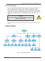
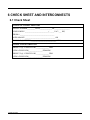
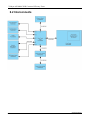
USER MANUAL
Model 702H
Converter Efficiency Tester
© TELEDYNE ADVANCED POLLUTION INSTRUMENTATION (TAPI)
9480 CARROLL PARK DRIVE
SAN DIEGO, CALIFORNIA 92121-5201
USA
Toll-free Phone:
Phone:
Fax:
Email:
Website:
Copyright 2014-2015
Teledyne Advanced Pollution Instrumentation
800-324-5190
858-657-9800
858-657-9816
[email protected]
http://www.teledyne-api.com/
08238A DCN7070
31 March 2015
Notice of Copyright
© 2014-2015 Teledyne Advanced Pollution Instrumentation. All rights reserved.
Trademarks
All trademarks, registered trademarks, brand names or product names appearing in this document are
the property of their respective owners and are used herein for identification purposes only.
08238A DCN7070
i
Teledyne API Model 702H Converter Efficiency Tester
This page intentionally left blank.
ii
08238A DCN7070
SAFETY MESSAGES
Important safety messages are provided throughout this manual for the purpose of avoiding
personal injury or instrument damage. Please read these messages carefully. Each safety
message is associated with a safety alert symbol, and are placed throughout this manual and
inside the instrument. The symbols with messages are defined as follows:
WARNING: Electrical Shock Hazard
HAZARD: Strong oxidizer
GENERAL WARNING/CAUTION: Read the accompanying
message for specific information.
CAUTION: Hot Surface Warning
Do Not Touch: Touching some parts of the instrument without
protection or proper tools could result in damage to the part(s)
and/or the instrument.
Technician Symbol: All operations marked with this symbol are
to be performed by qualified maintenance personnel only.
Electrical Ground: This symbol inside the instrument marks the
central safety grounding point for the instrument.
CAUTION
This instrument should only be used for the purpose and in the
manner described in this manual. If you use this instrument in a
manner other than that for which it was intended, unpredictable
behavior could ensue with possible hazardous consequences.
NOTE
Obtain technical assistance in the use and maintenance of this instrument or any other
Teledyne API product by contacting Teledyne API’s Technical Support Department:
Telephone: 800-324-5190
Email: [email protected]
or by accessing various service options on our website at www.teledyne-api.com/
08238A DCN7070
iii
Teledyne API Model 702H Converter Efficiency Tester
CONSIGNES DE SÉCURITÉ
Des consignes de sécurité importantes sont fournies tout au long du présent manuel dans le but
d’éviter des blessures corporelles ou d’endommager les instruments. Veuillez lire attentivement
ces consignes. Chaque consigne de sécurité est représentée par un pictogramme d’alerte de
sécurité; ces pictogrammes se retrouvent dans ce manuel et à l’intérieur des instruments. Les
symboles correspondent aux consignes suivantes :
AVERTISSEMENT : Risque de choc électrique
DANGER : Oxydant puissant
AVERTISSEMENT GÉNÉRAL / MISE EN GARDE : Lire la
consigne complémentaire pour des renseignements spécifiques
MISE EN GARDE : Surface chaude
Ne pas toucher : Toucher à certaines parties de l’instrument sans
protection ou sans les outils appropriés pourrait entraîner des
dommages aux pièces ou à l’instrument.
Pictogramme « technicien » : Toutes les opérations portant ce
symbole doivent être effectuées uniquement par du personnel de
maintenance qualifié.
Mise à la terre : Ce symbole à l’intérieur de l’instrument détermine
le point central de la mise à la terre sécuritaire de l’instrument.
MISE EN GARDE
Cet instrument doit être utilisé aux fins décrites et de la manière
décrite dans ce manuel. Si vous utilisez cet instrument d’une autre
manière que celle pour laquelle il a été prévu, l’instrument
pourrait se comporter de façon imprévisible et entraîner des
conséquences dangereuses.
iv
08238A DCN7070
Teledyne API Model 702H Converter Efficiency Tester
WARRANTY
WARRANTY POLICY (02024G)
Teledyne Advanced Pollution Instrumentation (TAPI), a business unit of Teledyne
Instruments, Inc., provides that:
Prior to shipment, TAPI equipment is thoroughly inspected and tested. Should equipment
failure occur, TAPI assures its customers that prompt service and support will be available.
COVERAGE
After the warranty period and throughout the equipment lifetime, TAPI stands ready to
provide on-site or in-plant service at reasonable rates similar to those of other manufacturers
in the industry. All maintenance and the first level of field troubleshooting are to be
performed by the customer.
NON-TAPI MANUFACTURED EQUIPMENT
Equipment provided but not manufactured by TAPI is warranted and will be repaired to the
extent and according to the current terms and conditions of the respective equipment
manufacturer’s warranty.
PRODUCT RETURN
All units or components returned to Teledyne API should be properly packed for
handling and returned freight prepaid to the nearest designated Service Center. After the
repair, the equipment will be returned, freight prepaid.
The complete Terms and Conditions of Sale can be reviewed at http://www.teledyneapi.com/terms_and_conditions.asp
CAUTION – Avoid Warranty Invalidation
Failure to comply with proper anti-Electro-Static Discharge (ESD) handling
and packing instructions and Return Merchandise Authorization (RMA)
procedures when returning parts for repair or calibration may void your
warranty. For anti-ESD handling and packing instructions please refer to the
manual, Fundamentals of ESD, PN 04786, in its “Packing Components for
Return to Teledyne API’s Customer Service” section. The manual can be
downloaded from our website at http://www.teledyne-api.com under Help
Center > Product Manuals in the Special Manuals section; RMA procedures
are under Help Center > Return Authorization.
08238A DCN7070
v
Teledyne API Model 702H Converter Efficiency Tester
ABOUT THIS MANUAL
The Model 702H manual is comprised of multiple documents, assembled in PDF format, as listed below.
Part No.
08238
Rev
A
Name/Description
Model 702H User Manual (this manual)
NOTE
We recommend that this manual be read in its entirety before making any attempt to
operate the instrument.
vi
08238A DCN7070
Teledyne API Model 702H Converter Efficiency Tester
REVISION HISTORY
This section provides information regarding the initial release and subsequent changes to this manual.
Model 702H User Manual
Date
Rev
DCN
31 Mar 2015
A
7070
08238A DCN7070
Change Summary
Initial Release
vii
Teledyne API Model 702H Converter Efficiency Tester
This page intentionally left blank.
viii
08238A DCN7070
TABLE OF CONTENTS
SAFETY MESSAGES .................................................................................................................. III
CONSIGNES DE SÉCURITÉ ......................................................................................................... IV
W ARRANTY ...............................................................................................................................V
ABOUT THIS MANUAL ................................................................................................................ VI
REVISION HISTORY................................................................................................................... VII
TABLE OF CONTENTS ................................................................................................................ IX
LIST OF FIGURES .......................................................................................................................X
LIST OF TABLES .........................................................................................................................X
1 INTRODUCTION ........................................................................................... 1-1
2 SPECIFICATIONS ........................................................................................ 2-1
3 GETTING STARTED..................................................................................... 3-1
3.1 UNPACKING ..................................................................................................................... 3-1
3.2 INSTALLATION .................................................................................................................. 3-1
3.3 INSTRUMENT LAYOUT ....................................................................................................... 3-2
3.3.1 Front Panel ............................................................................................................. 3-2
3.3.2 Rear Panel ............................................................................................................. 3-3
3.3.3 Internal Chassis Layout .......................................................................................... 3-4
3.4 CONNECTIONS AND SETUP ............................................................................................... 3-5
3.4.1 Electrical Connections ............................................................................................ 3-5
3.4.2 Pneumatic Connections ......................................................................................... 3-9
3.5 PNEUMATIC FLOW ......................................................................................................... 3-12
3.5.1 Calibration Gas..................................................................................................... 3-13
3.5.2 Ozone/GPT/GPTZ ................................................................................................ 3-13
4 OPERATION ................................................................................................. 4-1
4.1 USING THE CONTROLS AND DISPLAYS ............................................................................... 4-1
4.1.1 Viewing and Editing ................................................................................................ 4-1
4.1.2 Ozone Preset ......................................................................................................... 4-2
4.1.3 Display.................................................................................................................... 4-2
4.1.4 Status Indicators..................................................................................................... 4-2
4.1.5 Active Gas .............................................................................................................. 4-2
4.1.6 Cal Gas Pressure ................................................................................................... 4-3
4.2 MENU SYSTEM ................................................................................................................ 4-3
4.3 VERIFYING FLOWS ........................................................................................................... 4-4
4.3.1 Cal Gas Flow Verification: ...................................................................................... 4-4
4.3.2 Ozone Flow Verification:......................................................................................... 4-4
4.3.3 Ozone Pressure Verification: .................................................................................. 4-5
4.4 SETTING UP GPT ............................................................................................................ 4-5
4.4.1 To Adjust a Preset Value........................................................................................ 4-5
4.5 BASIC EQUATIONS ........................................................................................................... 4-6
08238A DCN7070
ix
Teledyne API Model 702H Converter Efficiency Tester
5 TROUBLESHOOTING AND MAINTENANCE .............................................. 5-1
5.1 TROUBLESHOOTING ......................................................................................................... 5-1
5.2 MAINTENANCE ................................................................................................................. 5-2
6 CHECK SHEET AND INTERCONNECTS..................................................... 6-1
6.1 CHECK SHEET ................................................................................................................. 6-1
6.2 INTERCONNECTS.............................................................................................................. 6-2
LIST OF FIGURES
FIGURE 3-1:
FIGURE 3-2:
FIGURE 3-3:
FIGURE 3-4:
FIGURE 3-7:
MODEL 702H FRONT PANEL ................................................................................................ 3-2
MODEL 702H REAR PANEL .................................................................................................. 3-3
MODEL 702H INTERNAL CHASSIS LAYOUT .......................................................................... 3-5
STATUS OUTPUT CONFIGURATION EXAMPLES ...................................................................... 3-8
PNEUMATIC CONNECTIONS WITH REQUIREMENTS FOR MINIMUM BACK-DIFFUSION/BACKPRESSURE ........................................................................................................................................ 3-10
FIGURE 3-8: MODEL 702H PNEUMATIC FLOW DIAGRAM ....................................................................... 3-13
FIGURE 4-1: MODEL 702H MENU STRUCTURE ......................................................................................... 4-3
LIST OF TABLES
TABLE 2-1: MODEL 702H SPECIFICATIONS .............................................................................................. 2-1
TABLE 3-1: FRONT PANEL DESCRIPTION ................................................................................................... 3-2
TABLE 3-2: REAR PANEL DESCRIPTION .................................................................................................... 3-4
TABLE 5-1: MODEL 702H TROUBLESHOOTING......................................................................................... 5-1
x
08238A DCN7070
1 INTRODUCTION
The Teledyne API Model 702H Converter Efficiency Tester is a low-cost, simple, light-weight
instrument for checking the converter efficiency of NOx analyzers. The basic unit uses two
bottles of different NO concentrations (0-10 PPM and 0-100 PPM) to generate NO2 to
perform converter efficiency checks. A high concentration ozone generator supports GPT
calibration.
The Model 702H features:
•
two cal gas inputs
•
one dry air input connection,
•
two ozone and GPT concentration presets,
•
one cal gas out connection
When the two NO cylinders are connected with the appropriate concentrations, the Model
702H will produce two concentrations, such as (20% URL) and “span” (80% URL) as well as
“zero”.
NOTE
The Model 702H has been checked out at the factory and meets all of
our test criteria. However, during shipment, regulator settings may
have shifted. Check the flows using NIST-Traceable flow standards
before using the Model 702H. See Section 4.3 for flow verification.
08238A DCN7070
1-1
Teledyne API Model 702H Converter Efficiency Tester
This page intentionally left blank.
1-2
08238A DCN7070
2 SPECIFICATIONS
Table 2-1: Model 702H Specifications
2 – 5 lpm
5 – 50 psig
400 ppm (@ 1 slpm); 5000 ppm @ 80 cc (maximum)
Bench (standard)
Rack (optional)
5 to 40°C
5.22 H x 19 W x 15-3” D
(133 x 483 x 362 mm)
20 lbs. (9.1 Kg)
Rating
Typical Power Consumption
100 - 120 V~ 63 Hz, 2.0 A
15 W
220 - 240 V~ 47 Hz, 2.0 A
14 W
Installation Category (Over Voltage Category) II Pollution
Degree 2
Intended for Indoor Use Only at Altitudes ≤ 2000 m
08238A DCN7070
2-1
Teledyne API Model 702H Converter Efficiency Tester
This page intentionally left blank.
2-2
08238A DCN7070
3 GETTING STARTED
3.1 Unpacking
Verify that there is no shipping damage.
If there are signs of damage, immediately contact the shipper, then Teledyne API.
Remove the cover and check for damage inside, particularly the glass GPT reaction chamber.
Check the line voltage decal on the rear panel. Verify that it matches your local power. (The
Model 702H is not frequency-sensitive.)
3.2 Installation
The rack-mounting is designed for a standard 19” RETMA rack. When installing the 702H,
check the following points:
•
At least 3” (75mm) at each side for proper ventilation.
•
Adequate support for the weight: 20 lbs (9.1 Kg).
•
Access at the rear for making pneumatic and electrical connections.
•
Access at the front for control and adjustments.
"CE" NOTE
When the Model 702H is operating, the cover must be in place and
all cover screws must be tightened. Otherwise the Model 702H may
violate "CE" standards for electromagnetic radiation.
08238A DCN7070
3-1
Teledyne API Model 702H Converter Efficiency Tester
3.3 Instrument Layout
3.3.1 Front Panel
Figure 3-1 illustrates the front panel of the Model 702H CE Checker.
Figure 3-1: Model 702H Front Panel
Table 3-1: Front Panel Description
Front Panel Component
Cal Gas Pressure
Regulator Control
Cal Gas Pressure Gauge
Display
Status Indicator LEDs
Menu, Navigation, and
Selection Control
Ozone Preset
Indicator LEDs
3-2
Description
Increases (when turned clockwise) or decreases (when turned
counterclockwise) the calibration gas pressure. See Cal Gas Pressure
Gauge.
DO NOT EXCEED 50 PSI
Needle indicates pressure of the calibration gas.
USE THE CAL GAS PRESSURE REGULATOR CONTROL TO KEEP
THE PRESSURE AT OR BELOW 50 PSI
Panel showing menu, status, or parameter value.
Each LED indicates current status of the instrument.
O3GEN ON
Solid lit when ozone is being generated (Typically
during GPT, but if lit when not in GPT mode, place in
STDY mode or power down the 702H and call TAPI
Tech Support)
REMOTE CAL
Solid lit during remote operation
PRESSURE ERROR Blinks when dry air pressure is outside limits
COMM ERROR
Blinks when communications fail
Used to enter and scroll through the menu system (), and to select and set
menu items.
During GPT mode, lit LED indicates which of two ozone presets is being
shown in the Display. (Neither LED is lit when instrument not in GPT mode).
08238A DCN7070
Teledyne API Model 702H Converter Efficiency Tester
Front Panel Component
Ozone Preset
Selector
Active Gas
Indicator LEDs
Standby Activation
Control
Power
Rocker Switch
Description
Functional only when in GPT mode, this selector can be either pressed and
released to toggle between presets, or pressed-and-held to edit presets
(Section 4.1.2).
Presets can also be managed through the menu system, (see Section 4.2).
Only one LED or neither will be lit:
Lit indicates which cylinder is in use. Not lit indicates not in use.
Not lit indicates not in use.
When pressed and immediately released, suspends operation as it places
the instrument in Standby mode. (Use the menu system, Section 4.2, to start
an operation).
Powers the instrument on and off.
3.3.2 Rear Panel
Figure 3-2: Model 702H Rear Panel
08238A DCN7070
3-3
Teledyne API Model 702H Converter Efficiency Tester
Table 3-2: Rear Panel Description
Rear Panel Component
AC power receptacle
Function
Connector for three-prong cord to apply AC power to the analyzer.
CAUTION! The cord’s power specifications (specs) MUST comply
with the power specs on the instrument’s rear panel label
Communications
Connectors
Currently under development, Ethernet or Serial communications will be
available for remote control and for status outputs.
CYL 1 IN
Input port for an NO bottle of known concentration
CYL 2 IN
Input port for an NO bottle of different, known concentration
DRY AIR IN
Input port for zero air from dry air canister
CAL GAS OUT
Output port for calibration gas to the Sample port of the analyzer being
calibrated
EXHAUST
Exhaust port to be connected to a proper, unpressurized vent manifold to
prevent exposure to ozone
3.3.3 Internal Chassis Layout
3-4
08238A DCN7070
Teledyne API Model 702H Converter Efficiency Tester
Figure 3-3: Model 702H Internal Chassis Layout
3.4 Connections and Setup
3.4.1 Electrical Connections
NOTE
To maintain compliance with EMC standards, it is required that the cable
length be no greater than 3 meters for all I/O connections, which include
Analog In, Analog Out, Status Out, Control In, Ethernet/LAN, USB,
RS-232, and RS-485.
WARNING
ELECTRICAL SHOCK HAZARD
High Voltages are present inside the analyzer’s case.
Power connection must have functioning ground connection.
Do not defeat the ground wire on power plug.
Turn off analyzer power before disconnecting or connecting
electrical subassemblies.
Do not operate with cover off.
CAUTION
GENERAL SAFETY HAZARD
To avoid damage to your instrument, ensure that the AC power
voltage matches the voltage indicated on the unit’s model/specs
label located on the rear panel before plugging it into line power.
3.4.1.1 Connecting Power
Adhering to all safety and cautionary messages, attach the power cord between the analyzer’s
AC power connector and a power outlet capable of carrying at least the rated current at your
AC voltage range; also ensure that it is equipped with a functioning earth ground.
08238A DCN7070
3-5
Teledyne API Model 702H Converter Efficiency Tester
3.4.1.2 Connecting Control and Communications
NOTE
In this version of the unit, Ethernet and serial communications are not implemented.
Status Outputs
The schematic for Status Outputs connections are located in the appendix of this manual.
There are four modes, two cylinders, two preset values, and three errors that can be monitored
through STATUS OUT.
Table 3-3. Status Outputs Contact Functions
CONTACT PAIR
FUNCTION
#1
DILUENT VALVE
#2
CYL 1 VALVE
#3
CYL 2 VALVE
#4
OZONE PRESET 1
#5
OZONE PRESET 2
#6
TEMPERATURE OK
#7
SYSTEM OK
These are uncommitted emitter/collector pairs and will sink 5 mA.
See Figure 3-4 for examples.
3-6
08238A DCN7070
Teledyne API Model 702H Converter Efficiency Tester
Table 3-4. Status Outputs Mode Truth Table
Pin #1
Pin #2
Pin #3
Pin #4
GPTZ
0
0
0
0
0
0
0
0
1
1
1
1
1
1
1
1
X
X
GPT
0
0
0
0
1
1
1
1
0
0
0
0
1
1
1
1
X
X
CYL1
0
0
1
1
0
0
1
1
0
0
1
1
0
0
1
1
X
X
CLY2
0
1
0
1
0
1
0
1
0
1
0
1
0
1
0
1
X
X
X
X
X
X
X
X
X
X
08238A DCN7070
Status Outputs
Pin #5
Pin #6
Pin #7
O3 GEN
Pressure
Preset
ON
Error
X
0
X
X
0
X
X
0
X
X
X
X
X
X
X
X
0
X
X
0
X
X
X
X
X
X
X
X
1
X
X
1
X
X
X
X
X
X
X
X
X
X
X
X
X
X
X
X
1
X
X
X
1
X
X
X
X
X
1
X
Pin #8
Comm
Error
X
X
X
X
X
X
X
X
X
X
X
X
X
X
X
X
X
X
X
1
Function
Standby
Cal Gas Cyl2
Cal Gas Cyl1
N/A
N/A
GPT Cyl2
GPT Cyl1
N/A
N/A
GPTZ Cyl2
GPTZ Cyl1
N/A
N/A
N/A
N/A
N/A
Preset 2
O3 Gen ON
Pressure
Error
Comm Error
3-7
Teledyne API Model 702H Converter Efficiency Tester
Figure 3-4:
3-8
Status Output Configuration Examples
08238A DCN7070
Teledyne API Model 702H Converter Efficiency Tester
Control Inputs
The schematic for Control Inputs connections are shown in the appendix of this manual.
There are four modes, two cylinders, and two presets that can be accessed through the
CONTROL IN connector.
CONTACT PAIR
FUNCTION
#1
DILUENT VALVE
#2
CYL 1 VALVE
#3
CYL 2 VALVE
#4
OZONE PRESET 1
#5
OZONE PRESET 2
These require a contact closure. Current is 30 mA.
Table 3-5. Control Inputs Mode Truth Table
Pin #5
Preset
x
x
x
x
x
x
x
x
x
x
x
x
x
x
x
x
0
Pin #4
GPTZ
1
1
1
1
1
1
1
1
0
0
0
0
0
0
0
0
X
Control Inputs (Active Low)
Pin #3 Pin #2 Pin #1
GPT
CYL2
CLY1
Function
1
1
1
Standby
1
1
0
Cal Gas Cyl1
1
0
1
Cal Gas Cyl2
1
0
0
Invalid
0
1
1
Invalid
0
1
0
GPT Cyl1
0
0
1
GPT Cyl2
0
0
0
Invalid
1
1
1
Invalid
1
1
0
GPTZ Cyl1
1
0
1
GPTZ Cyl2
1
0
0
Invalid
0
1
1
Invalid
0
1
0
Invalid
0
0
1
Invalid
0
0
0
Invalid
X
X
X
Preset #2
3.4.2Pneumatic Connections
Use clean 1/8” OD Stainless Steel tubing. Refer to Figure 3-5 when following connection
instructions in this section.
08238A DCN7070
3-9
Teledyne API Model 702H Converter Efficiency Tester
Figure 3-5: Pneumatic Connections with Requirements for Minimum Back-diffusion/Back-pressure
3.4.2.1 CYL 1 IN and CYL 2 IN
3-10
08238A DCN7070
Teledyne API Model 702H Converter Efficiency Tester
CAUTION
Make sure that the area is well ventilated.
If this is the first time that the gas cylinder (e.g., new cylinder) and a regulator are being
connected to the 702H:
1. Attach the cylinder regulator to the cylinder and tighten.
2. Attach the 1/8” stainless steel tubing to the regulator and tighten.
DO NOT ATTACH THE TUBING TO THE 702H.
CAUTION
Use clean 1/8" stainless steel tubing.
Do not use plastic tubing. It may burst. With nitric oxide
cylinders, atmospheric oxygen can permeate plastic
tubing and oxidize NO to NO2.
3. Close the regulator shut-off valve.
4. Open the cylinder valve.
5. Check the regulator for leaks using bubble solution.
6. Tighten if necessary.
CAUTION
If the regulator still leaks, turn off the cylinder valve immediately;
find the cause of the leak. (Could be missing washer or the like).
7. To prevent ambient air from flowing through the cylinder, thoroughly flush the cylinder
regulator several times, as follows:
a) Close the regulator shut-off valve.
b) Open the cylinder valve.
c) Turn the cylinder regulator up to 35-50 psig.
CAUTION
Do not exceed 50 PSIG at the cylinder regulator.
08238A DCN7070
3-11
Teledyne API Model 702H Converter Efficiency Tester
d) Close the cylinder valve.
e) Open the regulator shut-off valve to vent the regulator contents.
f) Repeat this once or twice more and then leave the regulator shut-off valve closed.
g) Connect the stainless steel tubing to the Model 702H rear panel CYL 1 IN union and
tighten.
CAUTION
With nitric oxide cylinders, do not allow air to enter the regulator
after purging. Oxygen will form NO2 with the NO.
The gas cylinder or other source must produce 2-5 LPM at 5 - 50 psig.
3.4.2.2 DRY AIR IN
The 702H is shipped with the dry air canister connected to the DRY AIR IN port; check that
the connections are intact.
3.4.2.3 CAL GAS OUT
Use CLEAN ¼” OD Stainless Steel tubing and a T-fitting to connect the CAL GAS OUT port
to the sample manifold of the analyzer being checked. Figure 3-5 illustrates the USEPAsuggested criteria for designing the sampling manifold.
CAUTION
The sample manifold must be properly vented. The Model 702H does
not have a built in vent. The vent should be a part of the manifold
and should be as close as possible to the analyzer sample inlet (See
tee-fitting in Figure 3-5). There must be only one vent in the manifold.
When connecting the Model 702H CAL GAS OUT port to the analyzer(s) to be calibrated, it
is very important that the analyzer sample inlet pressure be the same as its normal sampling
pressure.
3.4.2.4 EXHAUST
Although the 702H has an ozone scrubber, ensure that no ozone is being released into the
shelter by running tubing from the EXHAUST port to outside.
3.5 Pneumatic Flow
Refer to Figure 3-6 while reading the pneumatic flow descriptions.
3-12
08238A DCN7070
Teledyne API Model 702H Converter Efficiency Tester
Figure 3-6: Model 702H Pneumatic Flow Diagram
3.5.1 Calibration Gas
Calibration gas from each of two certified cylinders enters the rear panel at the ports marked
CYL 1 and CYL 2. Flow is controlled (ON/OFF) by manifold-mounted normally closed
solenoid valves, one valve for CYL 1 and one valve for CYL 2. The two CYL valves are
connected so that you may use either gas or neither (set via the Menu System), but not both at
once. Control the gas flow by adjusting the gas pressure regulator with the front panel knob
below the CAL GAS PRESSURE gauge and observing the gauge on the front panel.
3.5.2 Ozone/GPT/GPTZ
A low flow passes through the ozone generator (during GPTZ ozone concentration will be
0%), then mixes with the CAL GAS at the entrance to the reaction chamber.
The ozone reacts stoichiometrically with the NO (NO concentration must be at least 10%
greater than O3 concentration) in the reaction chamber to form NO2 with some NO remaining.
NOTE
Ensure that NO production is 10% more than O3.
The reacted product leaves through the rear panel CAL GAS OUT port.
08238A DCN7070
3-13
08238A DCN7070
4 OPERATION
This section begins with a description of how to use the front panel controls and displays.
4.1 Using the Controls and Displays
4.1.1 Viewing and Editing
The Menu, Navigation, and Editing control is used to access the menu system and to view and
edit parameters. (Figure 4-1 shows the menu structure).
•
MENU enters the menu system, backs out of a menu level, and escapes from a menu item. In
Preset edit mode the MENU button toggles across decimal places.
•
navigation and increment button scrolls up the menu system and, when in Preset edit mode,
increases the % value of the Ozone Generator drive.
•
navigation and decrement button scrolls down the menu system and decreases the value of a
setting when in Preset edit mode.
•
ENT accesses a submenu or initiates a function, or when in Preset edit mode accepts the
displayed value.
Summary:
•
Press the MENU button to access the menu system.
•
Press the navigation buttons
•
Press the ENT button to activate the menu item.
•
Press the MENU button to select the decimal place in edit mode, and press the increment
to scroll through the menu system.
or
decrement
buttons to change the value as desired (raise or lower the % of the Ozone
Generator drive) for PRESET 1 or PRESET 2, whichever is presently selected as indicated by the
LED in the OZONE PRESET window.
•
08238A DCN7070
Press the ENT button to accept the new value.
4-1
Teledyne API Model 702H Converter Efficiency Tester
4.1.2 Ozone Preset
Preset is used to set the upper range limit (URL) of each cylinder of Nitric Oxide. The Preset
button is only active while the instrument is in GPT mode, and can be either pressed-andreleased to toggle between the two preset values, PRESET 1 and PRESET 2, or pressed and
held to go into edit mode to change the Preset values.
NOTE
The following capabilities are currently in development:
• The Preset functions can also be controlled remotely via MODBUS or Ethernet, or
via contact closure through the CONTROL IN terminal strip on the rear panel.
• The status of these functions may be read remotely through MODBUS or
Ethernet, or through the STATUS OUT terminal strip on the rear panel.
4.1.2.1PRESET 1
Set the URL of Cylinder 1. PRESET 1 is typically used to generate 20% URL of the bottle that
was selected in the GPT menu.
4.1.2.2PRESET 2
Set the URL of Cylinder 2. PRESET 2 is typically used to generate 80% URL of the bottle that
was selected in the GPT menu.
4.1.3 Display
The digital display serves as “power on” indicator, and on startup displays “TELEDYNE API
702H”, and then goes into Standby mode (STBY). During operation, the display shows the
Menu system and settings.
4.1.4 Status Indicators
The LED that’s lit indicates either the current status of the Model 702H.
Refer to the Troubleshooting section to see causes and remedies for errors.
4.1.5 Active Gas
The Active Gas panel indicates which cylinder (CYL 1 or CYL 2) is active by the
corresponding LED that is lit, or if both cylinders are inactive (neither LED is lit). The front
panel menu turns on either CYL 1 or CYL 2 solenoid valve and turns off either or both.
(Either one or the other can be active, or both can be inactive, but both cannot be
simultaneously active).
4-2
08238A DCN7070
Teledyne API Model 702H Converter Efficiency Tester
4.1.6 Cal Gas Pressure
The CAL GAS PRESSURE knob controls the cal gas pressure regulator; turn clockwise to
increase pressure and counter-clockwise to decrease pressure. The regulator secondary
pressure is displayed on the pressure gauge above the knob. The regulator pressure gauge is
common to CYL 1 and CYL 2 (indicated by their respective LEDs in the Active Gas window
in front panel). The pressure gauge will read zero when neither CYL 1 nor CYL 2 is selected
(neither LED is lit), and the instrument is in Standby mode (indicated by STBY in the
display).
CAUTION
Do not exceed 50 PSIG or the MODEL 702H pressure gauge and
regulator may be damaged.
Remember to keep the pressure gauge in the upper half of its range for best resolution and
control.
4.2 Menu System
Figure 4-1: Model 702H Menu Structure
08238A DCN7070
4-3
Teledyne API Model 702H Converter Efficiency Tester
Menu Item
Description
GEN>CAL
generates a calibration of cylinder 1 or 2
GEN>GPTZ
generates a gas phase titration with ozone drive at 0% for cylinder 1 or 2
GEN>GPT
generates a gas phase titration for cylinder 1 or 2
PRESET>SET1
displays ozone % value stored in Preset 1 in Edit mode (most significant
digit will start blinking)
PRESET>SET2
displays ozone % value stored in Preset 2 in Edit mode (most significant
digit will start blinking)
VIEW>PRES
displays the current dry air pressure
VARS
displays the firmware version and serial number of the Model 702H (Comm
Addr is under development for future use).
4.3 Verifying Flows
Before running GPT, verify and record the Cal Gas and Ozone flows.
4.3.1 Cal Gas Flow Verification:
1. Connect a regulated cylinder of dry air to one of the cylinder inputs (CYL 1 or CYL2) on
the 702H (NO may be substituted for dry air depending on flow meter compatibility).
2. Connect the CAL GAS OUT and EXHAUST ports of the 702H to vent/atmosphere.
3. Generate GPTZ using the cylinder of dry air for several minutes to completely evacuate
the 702H of any gas concentrations.
4. Connect a (NIST Traceable) flow meter to the CAL GAS OUT port on the rear panel.
5. Generate GPTZ using the cylinder of dry air.
6. Adjust the CAL GAS PRESSURE knob on the front panel until the desired flow rate is
achieved. (Note: Clockwise increases pressure and flow. Also, generating Cal Gas will
reduce the total flow by approximately 80ccm).
7. Record the pressure on the front panel gauge.
8. Put the instrument in Standby.
4.3.2 Ozone Flow Verification:
1. Remove the cylinder of dry air from the input port, and cap both ports.
2. With the flow meter still installed, generate GPTZ using either of the capped inlet ports.
3. Press Menu>Exit to return to the top level menu.
4. Press View>Pressure>Enter to see the pressure value.
The pressure on the front panel display should be close to 12 PSI, and the flow out of the
Cal Gas Port shown on the flow meter should be close to 80 ccm. Record these values.
5. Return the instrument to standby mode and remove the caps and flow meter from the rear
panel.
4-4
08238A DCN7070
Teledyne API Model 702H Converter Efficiency Tester
4.3.3 Ozone Pressure Verification:
The ozone pressure may be checked anytime the 702H is generating GPT or GPTZ. From the
main menu, select View>Pressure>Enter. The display shows the current ozone regulator
pressure.
4.4 Setting Up GPT
By setting the correct flows and concentrations of nitric oxide and ozone, the nitric oxide
(NO) is stoichiometrically oxidized by ozone (O3) to nitrogen dioxide (NO2) using the EPAapproved Gas Phase Titration technique.
The USEPA prescribes specific rules for Gas Phase Titration of NO to NO2. See Basic
Equations, in Section 4.5.
Select the ozone-generator value (%) from the front panel by means of the Menu or by
PRESET button (if GPT is already running). As implied, the PRESET button selects one of
two preselected ozone lamp currents.
The usual preset ozone concentrations are:
•
0.20 of URL
•
0.80 of URL.
4.4.1 To Adjust a Preset Value
1. Press PRESET button (for Preset 1 or Preset 2).
2. Press the increment or decrement button until the desired concentration is shown in the
display.
3. Press ENTR to store the new value.
4. The allowable range of ozone concentrations is 400 ppm•LPM.
08238A DCN7070
4-5
Teledyne API Model 702H Converter Efficiency Tester
4.5 Basic Equations
The addition of ozone during the GPT and GPTZ modes changes the output gas according to the
following equations:
[NOx] out
=
[NO] cyl x (QNO / (QNO + QO3))
[NO2] out
=
[O3] x (QO3 / QNO + QO3)
[NO] out
=
[NOx] - [NO2]
[NOx] out
=
NOx concentration at CAL GAS OUT [ppm]
[NO] cyl
=
NO concentration in the cylinder [ppm]
[NO2] out
=
NO2 concentration at the CAL GAS OUT [ppm]
[NO] out
=
NO concentration at the CAL GAS OUT [ppm]
[O3]
=
Ozone concentration into the reaction chamber [ppm]
QNO
=
NO flow from the cylinder (LPM)
QO3
=
Ozone flow into the reaction chamber (LPM)*
QAIR
=
Dilution air flow into the reaction chamber (LPM)
where:
These equations are simplified during GPTZ because the ozone concentration is zero.
[NO] out
=
[NOx] out = [NO] cyl x (QNO / (QNO + QO3))
[NO2] out
=
0
* QO3 value should be pulled from the Final Test & Validation Data Sheet shipped with the
702H.
Converter Efficiency:
These NOX, NO and NO2 figures are predicated on a 100% efficient converter in the NOX
analyzer.
Refer to the Teledyne API NOX analyzer’s manual for determining converter efficiency.
4-6
08238A DCN7070
5 TROUBLESHOOTING AND MAINTENANCE
5.1 Troubleshooting
Table 5-1: Model 702H Troubleshooting
Problem
Probable Cause
Unplugged power cord.
Incorrect line voltage.
Display does not come on.
Tripped power switch/circuit
breaker.
15 VDC power supply failed.
Display cable disconnected.
Pressure regulator does
not respond.
Pressure source not connected.
Instrument is in Standby Mode.
Failed cylinder valve.
Pressure at intake too low.
Corrective Action
Plug in power cord at both
ends.
Refer to Table 2-1 for the
correct line voltage.
Untrip power switch/circuit
breaker.
Replace power supply.
Reconnect or replace display
cable.
Enter one of the generate
modes.
Turn on the selector valve.
Replace the cylinder valve.
Ensure that the NO bottle is
delivering sufficient
pressure.
Call TAPI Technical Support
Regulated pressure is too
low.
Possible leak.
No Ozone flow.
No ozone output.
Ozone generator lost power.
3-way O3 valve failed.
No communication to ozone
generator.
08238A DCN7070
Do NOT attempt to
leak check on site. The
reaction chamber must
NEVER be pressurized!
Ensure proper supply of
pressurized dry air/replace
internal pump.
Replace ozone generator
power cable.
Replace the O3 valve.
Replace I2C cable.
5-1
Teledyne API Model 702H Converter Efficiency Tester
5.2 Maintenance
For maintenance, contact Teledyne API Technical Support.
NOTE
Maintenance must be performed by qualified maintenance personnel
only.
CAUTION
Do not loosen any tubing connection while pressure
is applied to the Model 702H.
WARNING
Even though the front panel power switch is off, there is line
voltage present at the power entry terminals.
For added safety, remove the power cord from the rear panel
receptacle.
Teledyne API, Technical Support,
9480 Carroll Park Drive
San Diego, California 92121-5201USA
Toll-free Phone:
800-324-5190
Phone:
858-657-9800
Fax:
858-657-9816
Email:
Website:
5-2
[email protected]
http://www.teledyne-api.com/
08238A DCN7070
6 CHECK SHEET AND INTERCONNECTS
6.1 Check Sheet
CHECK OUT SHEET Model 702H
SERIAL NUMBER_________DATE______________BY_________________
LINE POWER? ___________________________( _____VAC/ ___ HZ)
PROM # _______________________________________
APPEARANCE __________________________________ OK
CAL GAS (@ 15 PSIG) ____________________________ CCM
OZONE CONCENTRATIONS
PRESET 1 (@ 15 PSIG FLOW) ______________ PPM.
(PPM x FLOW LPM)________________PPM•LPM
PRESET 2 (@ 15 PSIG FLOW) ______________ PPM.
(PPM x FLOW LPM)________________PPM•LPM
08238A DCN7070
6-1
Teledyne API Model 702H Converter Efficiency Tester
6.2 Interconnects
6-2
08238A DCN7070
APPENDIX – Status Outputs and Control Inputs Connections
08238A DCN7070
D-1
This page intentionally left blank.
D-2
08238A DCN7070
08238A DCN7070
D-3
702H Status Outputs
D-4
08238A DCN7070
702H Control Inputs