1
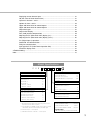
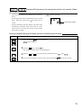
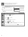
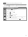
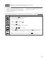
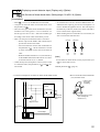
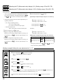
Displaying current detector input ............................................................................... 51
Hb (Set value of heater break alarm) ......................................................................... 51
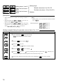
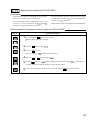
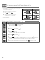
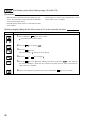
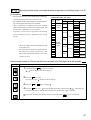
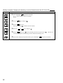
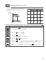
Hysteresis of alarm 1 and 2 ....................................................................................... 53
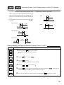
Options of alarm 1 and 2 ........................................................................................... 54
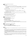
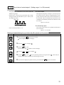
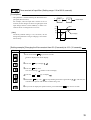
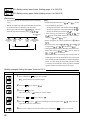
Upper and lower limits for control output 1 ................................................................ 56
Upper and lower limits for control output 2 ................................................................ 56
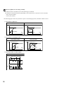
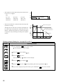
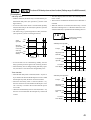
Output limit types ....................................................................................................... 57
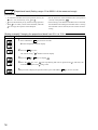
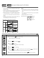
Output value display .................................................................................................. 58
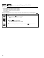
RCJ (Cold junction compensation) ............................................................................ 59
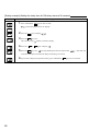
Adjusting the PV (Measured value) display (0%) ....................................................... 60
Adjusting the PV (Measured value) display (100%) ................................................... 60
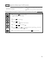
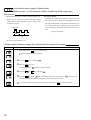
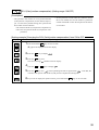
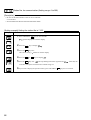
DI1 (Digital input 1) operation .................................................................................... 61
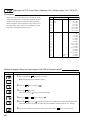
Station No. for communication ................................................................................... 64
Parity for communication ........................................................................................... 65
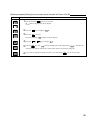
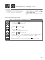
Input type for PYP (Color Touch-Operation Unit) ....................................................... 66
Parameter display mask ............................................................................................ 67
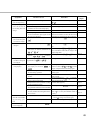
3 Troubleshooting ...................................................................................................................... 68
Index ......................................................................................................................................... 70
Model Specifications
P X R
4
FRONT PANEL SIZE
1/16 DIN screw terminal type
CODE
4
INPUT SIGNAL
Thermocouple °C
Thermocouple °F
RTD (Pt100) °C
RTD (Pt100) °F
4–20mA DC, 1-5V DC
0–20mA DC, 0-5V DC
CODE
T
R
N
S
B
A
CONTROL OUTPUT 1†
Relay (SPDT) (reverse action)
Relay (SPDT) (direct action)
SSR driver (reverse action)
SSR driver (direct action)
4–20mA DC (reverse action)*
4–20mA DC (direct action)*
CODE
A
B
C
D
E
F
* Not available with heater break alarm
** Not available with heater break alarm w/ process alarm
(1 point) or process alarm (2 points)
*** Not available with RS485 + digital input (1 point). Current
transformer required. Please specify part # (at right).
† 0-10V DC output — future option
†† SSR and 4-20mA DC, 0-10V DC — future option
1
V
ADDITIONAL OPTIONS
None
With RS485 (Modbus)
With digital input (1 point)
With RS485 (Modbus) + digital input
(1 point)
CODE
–
R
DI
DI-R
ALARM OPTIONS
Heater break alarm w/
process alarm (1 point)***
None
Process alarm (2 points)
CODE
3
CONTROL OUTPUT 2 ††
None
Relay (SPST) (reverse action)**
Relay (SPST) (direct action)**
CODE
Y
A
B
ACCESSORIES
Current Transformer 1-30A
Current Transformer 20-50A
Signal Converter RS485 to RS232
4
5
Part #
CTL-6-S
CTL-12
RSFC24
Program Loader
PXR4 loader assembly, includes free software
3