1
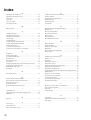
Table of Contents
1 Part Names and Functions .................................................................................................... 4
2 Operations ............................................................................................................................. 5
2-1 Parameter list ............................................................................................................ 5
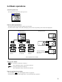
2-2 Basic operations ....................................................................................................... 9
2-3 Parameter functions and method of settings ............................................................ 10
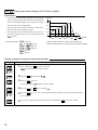
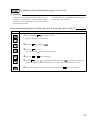
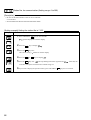
Standby setting .......................................................................................................... 11
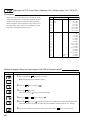
Ramp-soak control ..................................................................................................... 12
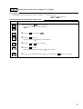
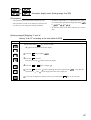
Canceling the alarm latch .......................................................................................... 13
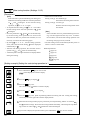
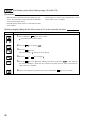
Auto-tuning function ................................................................................................... 14
Displaying ON-delay alarm or the remaining time of timers ...................................... 15
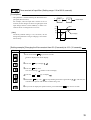
Setting alarm 1 and 2 ................................................................................................. 16
Upper limit of alarm 1 and 2....................................................................................... 16
Lower limit of alarm 1 and 2....................................................................................... 16
Key lock ..................................................................................................................... 17
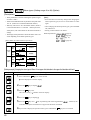
Proportional band ...................................................................................................... 18
Integral time ............................................................................................................... 19
Derivative time ........................................................................................................... 20
Hysteresis range for ON/OFF control ........................................................................ 21
Cooling-side proportional band coefficient ................................................................ 22
Cooling-side proportional band shift (Dead band/Overlap band) .............................. 23
Output offset value ..................................................................................................... 24
Anti-reset windup ....................................................................................................... 24
Control algorithm ....................................................................................................... 25
PV (Measured value) stable range ............................................................................ 29
HYS (Hysteresis) mode at ON/OFF control ............................................................... 30
Cycle time of control output 1 .................................................................................... 31
Cycle time of control output 2 (Cooling-side) ............................................................. 32
Input signal code ........................................................................................................ 33
Setting the measuring range (Input range) ................................................................ 34
Selection °C / °F ........................................................................................................ 34
Decimal point position ................................................................................................ 36
PV (Measured value) offset ....................................................................................... 37
SV (Setting value) offset ............................................................................................ 38
Time constant of input filter ........................................................................................ 39
Alarm types ................................................................................................................ 40
Selecting ramp-soak execute type ............................................................................. 43
Ramp-soak status display .......................................................................................... 44
1st to 8th target SV .................................................................................................... 44
1st to 8th ramp segment time .................................................................................... 44
1st to 8th soak segment time ..................................................................................... 44
Ramp-soak modes ..................................................................................................... 44
Specifying control action and output direction at input burn-out ................................ 47
SV (Setting value) lower limiter .................................................................................. 48
SV (Setting value) upper limiter ................................................................................. 48
The time of ON-delay alarm or timer function ............................................................ 49
2