1
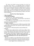
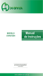
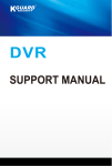
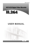
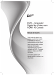
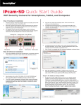
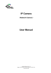
AHD Series HD iDVR Fast User Manual Directory: Part One: Basic Operation....................................................... ............................................ ..........................................2 1. Basic Installation................................................ .................. .................................................... ............................2 1.1 HDD Installation............................................. .................. ................................... .............................................2 1.2 Mouse Connection........................................................ .................. ............................. .....................................2 2. Startup......................................................................................................................... ...........................................2 3. Turn off......................................................................................................................... ..........................................2 4. Login..................................................................................................................... ... . .............................................2 5. Preview...................................................................................................................... ............... ..............................3 6. Recording Configuration ............................................................................................ .........................................3 7. Snapshot Storage(partial model support) .....................................................................................................4 8. Playback................................................................................. ..................................................... ...........................5 9. Network.................................................................................................................. ...............................................6 10.Alarm..................................................................................................................... .... .. ........... ............................7 10.1 Motion .................................................................................................................. .. ........... …......................7 10.2 Video Analysis............................................................................................ ........................... .. ............ ........7 11. PTZ Control ................................................................................................................ .....................................11 12. Access device in public network (Cloud operation) ...................................................................................11 12.1 Guide.............................................................................................................. .... ...........................................11 12.2 Login by user .......................................................................................................... .......................................11 12.3 Login by device.................................................................................................................. ...........................15 Part two: Remote Monitor..................................................................................................... .............. ..........................16 1. Remote Monitor............................................................................................................ ..........................................17 1.1 CMS.................................................................................................................................................... ...............17 1.2 WEB...................................................................................................................... ................................ .............17 2. Basic Remote Monitor Operation ..................................................................................... ................................18 2.1 Screen Split.................................................................................................................. .......................................18 2.2 Playback................................................................................................................. . ... ....................... ................18 2.3 Log...................................................................................................................... . ....................... ..... .................18 2.4 Local Config.......................................................................................................... ....................... ........ .... ........18 2.5 Channel Control.................................................................................................... ....................... .............. .......18 2.6 Remote Config.......................................................................................................... . ...................... ........ .........18 Part three: Special Function ................................................................................................. ....................... .... .........18 1. Encode Setting.................................................................................................... ............ ....................... .................20 1.1 Encode of separated channel setting ......................................................................................................20 1.2 Extra Stream..........................................................................................................................................................20 2. Multi-channel Playback Synchronous ......................................................................................................20 3. Multi-channel realtime transfer via network ......................................................................................................21 4. Mobile Monitor..................................................................... .............................................. ....... ................... ..........23 5. File Storage.............................................................................................................. .................................................23 6.AHD series special function................................................................................................ ................... ..................23 6.1 SPOT output(only partial model support)..............................................................................................................23 6.2 SDI input(only partial model support).................................................................................... ........................... ...23 6.3 Channel type select................................................................................................................... .............................23 6.4 Standard HDMI output ........................................................................................................................................25 Appendix 1.Remote Controller Operation....................................................................................... .................................25 Appendix 2.Mouse Operation................................................................................................................... ........................25 Warranty Card Error! Bookmark not defined. .......................................................................... ...............................25 12000 Ford Road, Suite 110, Dallas, TX 75234 Tel: 972-247-1203 Fax: 972-247-1291 www.idview.com Summary: Thank you for purchasing our re c o r d i n g te c h n o l o g y . This se r i e s of DVR integrates High Definition video, Intelligent motion detection and a Tr i - b r i d de s i g n , to give you, our esteemed customers the best of breed protection. The technical path of multiple networks, intelligent analysis, enterprise level CMS make the DVR feature rich, yet, ease of use and expandable. Main Features: DVR/HVR/NVR 3 in 1 Cloud Technology IVS (Intelligent video analysis system) High definition and Tri-brid Intelligent and Automatic Cloud technology - 1 step internet connection informative and Mobile Part One: Basic Operation 1. Basic installation 1.1 HDD installation Please install the Hard disk before the first use of this product. Please connect power cable and data cable correctly, our product can support 1, 2, 4 or 8 HDD, the number of HDD that can be support depends on which model was purchased.(Remark: the device can run normally without HDD, but cannot record and playback without it ) 1.2 Mouse connection There is one or two USB port on the back panel(one of the back ports is the same as on the front panel and one USB at front panel, both can be used for mouse, flash disk, WIFI or 3G module, etc. 2. Startup Connect with power, turn on the switch located on the back panel, when the indicator is on, then the DVR is turned on. After starting up, you will hear a beep; the default output mode is multi-window mode. Note: Restart the power after the unit is powered down abnormally, the DVR will automatically recover the state before it was powered off. 3. Turn off There are two methods to turn off the DVR; soft switch and hard switch. Soft switch: Entering [Main menu] and choosing [Logout] in the [turn off the system] option is called soft switch. Pressing the power supply switch is called hard switch. Note: The setting information must be saved before replacing the battery otherwise information will be lost. 4. Login When the DVR boots up, user must login and the system provides the corresponding functions with the user preview. There are two user settings; admin (Default Password: 123456), and guest (No password). “Admin” is a super user preview; “Guest” is the preferred user for preview and playback. You can modify the password for Admin and Guest, but cannot modify the authorities of them . Pic 1 : Login Password protection: If the password is continuously entered wrong three times, the alarm will sound. If the password is continuously entered wrong five times, the account will be locked. (Through reboot or after half an ho ur, the account will be unlocked automatically). 5. Preview 12000 Ford Road, Suite 110, Dallas, TX 75234 Tel: 972-247-1203 Fax: 972-247-1291 www.idview.com 2 / 25 Login normally and choose the multi-menu preview status. The system date, time and channel title are shown in each viewing window. The surveillance video and the alarm status are shown in each window. Chart 1 icon on preview window 6. Recording Configuration Set the recording parameters in the surveillance channel. You can enter [Main Menu]> [Record Channel]> [Record Config] to set. The system’s default setting is 24 hours continuous recording. Note: There is at least one read-write hard disk if the DVR records normally.(refer to chapter 4.5.1 HARD DISK Manage) Pic 2 Recording Config 【Channel】Choose the corresponding channel number to set the channel. Choose the “all” option to set the entire channels. 【Redundancy】Choose the recording file and backup in two hard disks. The one is read-write disk, another is redundant disk. (refer to 4.5.1 in reference CD) 【Length】Set the time length of each video file. 60minutes is default length. 【Pre-record】Record 1-30 seconds before the action. (File length is decided by the stream) 【Record Mode】Set video state: Schedule, manual and stop. Schedule: Record according to the set video type (regular, detect and alarm) and time section. Manual: Click the “all” button and make the corresponding channel recording no matter it is in any state. Stop: Click the “stop” button and make the recording channel stop recording no matter it is in any state. 【Period】Set the time section of common recording, The recording will start only in the set range. 【Recording Type】Set recording type: regular, detect or alarm. Regular:Perform the regular recording in the set time section. The video file type is “R”. Detect:Trigger the “motion detect”, “video blind” or “video loss” signal. When above alarm is set as opening recording, the “detection recording” state is on. The video file type is “M”. Alarm:Trigger the external alarm signal in the set time section. When above alarm is set as opening recording, the “detection recording” state is on. The video file type is “A”. 7. Snapshot storage (Partial model support) Based on settings to save the monitor image 12000 Ford Road, Suite 110, Dallas, TX 75234 Tel: 972-247-1203 Fax: 972-247-1291 www.idview.com 3 / 25 Parameter setting: 【Main menu】>【Record Channel】>【Snapshot】to do related setting, see pic 3, the function is closed in default. Note: If normal snapshot storage, please set Snap at 【Main Menu】->【Advanced】->【HDD Manage】->【Snapshot】 (please refer to chapter 4.5.1 HDD Manage) Pic 3 Snapshot Please refer to “6 record settings”. 8. Playback There are two methods for you to play video files in the hard disk. 1. In the desktop shortcut menu. 2. Main Menu>Playback. Enter the playback interface; you can playback video of multiple channels at the same time. Note: The hard disk that saves the video files must be set as read-write or read-only state. (Refers to 4.5.1 HARD DISK management) Pic 4: Playback 1. back up options 2.file info 4. File backup 5.operation hint 3. file searching 6.play control key 【File option】Choose the file to playback/backup. 12000 Ford Road, Suite 110, Dallas, TX 75234 Tel: 972-247-1203 Fax: 972-247-1291 www.idview.com 4 / 25 【File information】Start time, end time and size. Note: The storage must be large enough before the file backup. 【File searching】Search the file according to the searching parameter. 【File Backup】Backup files from HDD 【operation hint】Display the function of the cursor place. 【playback control】Refer to the following sheet for more information. Chart 2: Playback control key Note:Frame by frame playback is only performed in the "pause" playback state. Special functions: Special function: Accurate playback Input time (h/m/s) in the time column and then click playback. Local zoom: When the system is in single-window full-screen playback mode, you can drag your mouse on the screen to select a section and then left click to local zoom. You can right click to exit. 9. Network Doing network setup through [Main Menu]>[Network] 【IP address】Set the IP address. Default: 192.168.1.10. 【Subnet Mask】Set the subnet mask code. Default: 255.255.255.0. 【Gateway】Set the default gateway. Default: 192.168.1.1. Pic 5: Network setting Make the equipment’s IP address and the router in the same network segment. For example, the router IP address is 192.168.1.1, and the subnet mask is 255.255.255.0. According to the default setup, generally the default gateway is the router IP address, so enter IP address 192.168.1.10 in the IE browser to achieve visiting LAN equipment such as operating image surveillance in the public network remote access equipment for monitoring. Detail setups refer to “Network setup reference”. 12000 Ford Road, Suite 110, Dallas, TX 75234 Tel: 972-247-1203 Fax: 972-247-1291 www.idview.com 5 / 25 10. Alarm 10.1 Motion Detect Pic 6 Motion Detect Motion Detection Setup: Set DVR equipment making it alarm, linkage record and make the PTZ turn to preset position when there is a moving object in designated areas during Monday to Friday. Step1. Choose【Main Menu】>【Alarm】>【Motion Detect】, then enter the setup interface; Step2. Choose one channel and adjust sensitivity level, then set the time period of alarm surveillance. Set the monitor area (click the “set” button, choose the areas you want, and the “default” means choose all areas, then right click to choose "up window". Step3. When at alarm state, the DVR can take linkage measures. Alarm output, recording, tour, PTZ activation, snapshot, show message, sending email (need to set email parameters at net service)and buzzer (local buzzer). Step4. Set other channels alarm parameter following step 2 and step 3. Note: Video blind, video loss and alarm input’s setup method are similar with motion detection. 10.2 Video Analysis Pic 7 Video analysis 【Video analysis function】: can set in two rules: picket line and picket area Picket line rules: can be set to forbid bi-directional, from up to down (from left to right), from down to up(from right to left), 2 forbidden directions, when the moving objects meet the picket line rules, alarm will occurred. (Note, when it is set over pitched,it will show the direction from left to right / from right to left, otherwise will show that of from up to down / 12000 Ford Road, Suite 110, Dallas, TX 75234 Tel: 972-247-1203 Fax: 972-247-1291 www.idview.com 6 / 25 from down to up Rules: can be set to forbid bi-directional, enter, leave, 3 directions, when the moving objects meet the picket area rules, alarm will be activated Step 1: [Main Menu]> [Alarm]> [Intelligent Video analysis], enter video analysis setting interface, enable this function. Step 2: click rule to enter the rule setting interface, see pic 8: Pic 8 Rule setting Step 3: enable show track function, adjust level of sensibility and minimum image distance. Set picket mode, choose picket line or picket area, click setting to enter the “Config” interface, right click the mouse and choose add, use mouse to set two or more points then connect to form a line or a irregular area, after that will come out an option box of forbidden direction, choose one of them and right click mouse, then click yes return to pre-interface, click yes to finally finish alarm rules setting. Step 4: setting steps of alarm control period and the taken linkage measures is the same as step 2 and step 3 in alarm setting 10.1 Step 5: when video analyze alarm happens, there will be red box line in the preview image. The intelligent analyze function mainly including below 4 facets: 1. Perimeter detection(PEA) (1). touch line detection: bi-directional touch line, single-direction touch line (2). Area detection: enter alarm, leave alarm 12000 Ford Road, Suite 110, Dallas, TX 75234 Tel: 972-247-1203 Fax: 972-247-1291 www.idview.com 7 / 25 2. Items Care(OSC) Detect the change of goods status will trigger the alarm. The change can be goods left in the scene, or the goods are moved or lost. Main function: items left or stolen or moved. (1). Detect that something was dropped from the motor bike. (2). The car stopped in the forbidden parking area on the street. 12000 Ford Road, Suite 110, Dallas, TX 75234 Tel: 972-247-1203 Fax: 972-247-1291 www.idview.com 8 / 25 3. Flowmeter count (CPC) The head count of people passing in and out of a room, which is fit for flow statistic in simple indoor narrow passages. 4. Abnormal video signal diagnosis (AVD) Auto-detect that there is mess of skid bars, ripple, or a burst of flying spot, thorn or thread type of interference in the video image that lead to image fuzz, twisted, snow, flicker, scrolling, etc. 12000 Ford Road, Suite 110, Dallas, TX 75234 Tel: 972-247-1203 Fax: 972-247-1291 www.idview.com 9 / 25 11. PTZ Control To do simple PTZ control via below steps: Step 1: 【Main Menu】>【System】>【PTZ】, to set parameter of channel, protocol, etc. Step 2: under preview status to enter single window of PTZ control; Step 3: single click right button, choose PTZ control to control the normal function, or choose high-speed, click left button can operate PTZ directly, the moving of mouse is to control the direction of PTZ, use the rolling can to zoom in or zoom out of the camera. 12. Access device in public network (Cloud operation) 12.1 Guide If this is your first time using this, please start here (or follow the introduction in chapter 12.3 to login), if not, please skip . (1)Login cloud service website: http://xmeye.net 12000 Ford Road, Suite 110, Dallas, TX 75234 Tel: 972-247-1203 Fax: 972-247-1291 www.idview.com 10 / 25 (2)Follow the guide to install it step by step (3) Click ”next”, search for IP address: 12000 Ford Road, Suite 110, Dallas, TX 75234 Tel: 972-247-1203 Fax: 972-247-1291 www.idview.com 11 / 25 (4)Click “Next”, see pic as below: (5)Click “Next”, see pic as below: (6) Click “Next”, to enter the interface of user registration, see below pic: 12000 Ford Road, Suite 110, Dallas, TX 75234 Tel: 972-247-1203 Fax: 972-247-1291 www.idview.com 12 / 25 (7) Click “Next”, show the device serial number (8)Click “Next”, enter the interface to finish registration, see below pic: 12000 Ford Road, Suite 110, Dallas, TX 75234 Tel: 972-247-1203 Fax: 972-247-1291 www.idview.com 13 / 25 (9) Click “finish”, the following prompt will show: 12.2 Login by User. (Base on user to login can manage multi device) (1)Enter www.xmeye.net, choose”by user”, input user name and password to login. (2)After login, you can click “add device” to add more devices. 12000 Ford Road, Suite 110, Dallas, TX 75234 Tel: 972-247-1203 Fax: 972-247-1291 www.idview.com 14 / 25 (3)Enter “my devices” interface, double click device name, can see the monitor image. 12.3 Login by device (1)Enter main page of www.xmeye.net, choose “by device”, enter the serial no of device (can find out serial no from firmware version Main Menu->Info->Version) (2)Cloud server will shift to the monitor interface directly. (Note: visit by device can manage one device only) 12000 Ford Road, Suite 110, Dallas, TX 75234 Tel: 972-247-1203 Fax: 972-247-1291 www.idview.com 15 / 25 Part two: Remote Control 1. Remote Control After successfully connecting to the network, users can remote monitor in two ways: multi-device client software or a common browser. Multi-device client software CMS is professional software used for remote monitoring of multiple devices, with the merit of safety, convenience, stability and centralized management, etc, and also there is no need to install activeX, suggest the user do it. Browser is a kernel browser in PC itself, such as IE, etc. 1.1 Multi-device manage platform software - CMS CMS can centralize manage DVR in different spot on one PC. Step 1: get CMS software from CD that enclosed with DVR, follow the tips to install it. Step 2: After installing this software on the local PC, log into the interface as in picture 7, Enter the add device interface through【System】>【Device Manager】>【Add zone/device】, enter the device adding interface, follow the tips to input DVR information, exit after save it. Step 3: repeat above operation steps on the interface of device manage, can add multi device for centralize management. 12000 Ford Road, Suite 110, Dallas, TX 75234 Tel: 972-247-1203 Fax: 972-247-1291 www.idview.com 16 / 25 1.2 Web Monitor When connected to the network, use the browser of PC to login DVR for remote control. Step 1: install ActiveX, file name is “IE Plug_V1.1.0.78.exe”, which can be got from the CD attached, follow the tips to install it. Step 2: connect device, open browser, input the IP address of device, for example, the IP is 10.2.2.88, then input http://10.2.2.88 at the address column, will enter below page: WEB login interface Step 3: Log in, input user name and password. (If you choose to link with all the video after login, you will need to choose network stream, LAN use main stream to transfer, WAN use the extra stream to transfer, we suggest choosing extra streaming if your network is poor). The default administration is admin, no password. User should revise password of admin after loging in. Below pic 9 is the interface after successful login. Pic.9 WEB interface 12000 Ford Road, Suite 110, Dallas, TX 75234 Tel: 972-247-1203 Fax: 972-247-1291 www.idview.com 17 / 25 2.Basic remote control operation To perform remote control at the interface as seen in pic 9 2.1 Screen Split Choosethe mode of preview 2.2 Playback Enter playback area, can support multi-channel playback at the same time. 2.3 Log Show with log information 2.4 Local config To set device alarm, enable linkage function on the remote network client side. 2.5 Channel control Open the video, choose the video on the left video window and then choose channel on the right, double click it to open the first video, choose another one channel, double click to open the second video, use the same way to open other channels. If the channel did not change, system will closed previous video and open the new one you choose. Note: User can choose most appropriate image mode, when open remote video control Close video: at the video window, choose the video that you want to turn off, right click it and choose shut the window, also can choose shut all the windows to close all the video. 2.6 Remote config device At preview window, single click right button, choose device config, to config the parameter of device, which will be synchronized to local side, including: record, alarm, system, advanced, Info, etc. Part Three: Special Function This series trend towards humanize design, visualize operation key, partial enlargement in any region of preview interface, regular boot and shutdown, FTP upload, support WIFI function, etc, greatly meet user’s needs. Here e specially introduced encode settings, multi-channel playback, mobile monitor settings. 1. Encode To set encode parameter, in order to achieve high quality of playback and remote monitor effect... Pic 10 Encode 1.1 Encode of separated channel setting Step 1: Local operation,【Main Menu】>【 System】>【 Encode】 ( Remote setting is right click on the window and then choose Device Config at 【System】>【Encode】 ) ; Step 2: Choose channel one, set resolution with D1, frame rate with 20, byte rate value 1024; Step 3: Choose channel two, set resolution by CIF, frame rate by 25, byte rate value 512. Right click or local choose advanced, and click copy Step 4: Choose channel three, single right click or local choose advanced, choose paste. Same as channel four. Remark: 1, the reference range: D1 ( 512~2560kbps ), HD1(384~2048kbps) CIF(64~1024kbps), QCIF (64~512kbps) ,1080P (1024~8196kbps, partial model support this function) 2、Audio/Video icom both inverse, the record file should be audio and video composite flow 1.2 Extra stream config 12000 Ford Road, Suite 110, Dallas, TX 75234 Tel: 972-247-1203 Fax: 972-247-1291 www.idview.com 18 / 25 Extra stream is used for client side monitoring and mobile monitoring Step 1: Enable extra streaming Step 2: Configure frame rate, code stream value, the setting way is the same as separated channel parameters. 2. Multi-channel playback at the same time 4ch device can achieve 4ch playback at the same time, 8ch device can achieve 8ch playback at the same time, and channel no. can be combined freely. Pic 11 Playback Step 1:【Main Menu】>【Record】>【Record】,to set record parameter of each channel; Step 2: Enter playback interface, click Search key; Step 3: at search condition interface, choose file type, choose channel (channel can combine freely), choose time period, click yes; Step 4: at playback page, choose the video file, press play or double click the file to play back 3. Multi-channel real-time transfer via network Use extra stream technology, to real-time remote monitor multi-channel under the narrow bandwidth (or poor network conditions) Pic 12 CMS 12000 Ford Road, Suite 110, Dallas, TX 75234 Tel: 972-247-1203 Fax: 972-247-1291 www.idview.com 19 / 25 Step 1: same as “1.2 extra stream config”, enable extra stream. Step 2: open CMS, login software Step 3: after adding related device, choose window, select related channel at device list, right click, choose to connect all video (you can choose main stream or extra stream, based on network environment) 4. Mobile Monitor It introduces extra stream techniques when mobile monitoring, support channels switch (eg. Windows mobile) Step1. DVR config, go to [Main Menu]->[System]->[Encode], enable Extra Stream. Step2. Install mobile monitor software to cell phone, get the software from CD enclosed, (the software for android mobile is vMEyeSuper.apk ) Step3. After successfully installing the software, finding and running "eg. vMEyeSuper mobile-moveeye" software through [start]->[procedure] in the mobile, see picture 13 Pic 13 Mobile client side interface Step4: click device list on above, input the IP address, user name, password, and port no. of the device that need to be monitored. • Device Name: user can set it as he like. • User name: login name of device • Password: password of device • Server: IP address of device • Port: 34567 (Remark: the port no. for vMEyeSuper is default with 34567). After added device, click yes, will see pic 14, choose the channel you want to monitor, the preview image will be displayed. 12000 Ford Road, Suite 110, Dallas, TX 75234 Tel: 972-247-1203 Fax: 972-247-1291 www.idview.com 20 / 25 Pic: 14 mobile monitor interfaces Remark: when the DVR is in local area network, the mobile should connect to wireless router to access the device, each kind of mobile related to different client software ( due to different version, you should follow the version in the CD) Symbian S60 the 3rd operation system mobile monitoring client software: MEYE_SB_S60_3rd.sisx Symbian S60 the 5th operation system mobile monitoring client software: MEYE_SB_S60_5th.sisx Android mobile monitoring client software: vMEyeSuper.apk Blackberry mobile monitoring client software: MEYE_RIM.cod Remark: Iphone mobile monitoring software: use mobile to search "vMeyeSuper" in the appstore and install it online. 5. File storage Remark: different model with different supporting detail, please contact with customer service。 DVR introduces several unique storage and backup techniques to achieve multiple modes storage and backup. Real-time storage Redundant storage: DVR introduces RAID1 storage technique to achieve two hard disks storing simultaneously and mutual backup. USB HDD and movable hard disk: DVR introduces the storage technique, supporting video files which are real-time written in storage devices. DVD-RW: DVR introduces the newest real-time storage technique, supporting video file which are burnt real-time to CD. Real-time remote storage: DVR supports video files real-time storing to computer devices (Disk C/D/E/F) at the remote client. File download Using U disk and movable hard disk download at local device, DVR supports the chosen file are high-speed backup to the storage devices. DVD-RW: DVR supports the chosen video file are burnt and stored as CD. Network high-speed download: DVR supports high-speed down loading the chosen file at remote client. 6. Special feature of AHD Series Compare with 5000 series, AHD series add functions of SPOT output, SDI input and multi-mode of channel for selection. This series has different kinds of mode, Users can follow their favor to select DVR mode, HVR mode or NVR mode, also we add intelligent analyze function, since these four functions can be achieved in one device at the same time, so it is called Four in One, moreover, AHD series is with HDMI output as a standard configuration. 6.1 SPOT output function (only partial model can support) AHD series products have 2 BNC output port, one of them support SPOT output, user can shift SPOT output split image mode through right click menu. Note: if connect this BNC, no matter how you operate on VGA output, TV side always show the preview screen, can not show he GUI interface. 12000 Ford Road, Suite 110, Dallas, TX 75234 Tel: 972-247-1203 Fax: 972-247-1291 www.idview.com 21 / 25 6.2 SDI port input function (only partial model can support) This port can connect with video with resolution of 1080P 6.3 Channel mode selected function: AHD series product has channel manage function, 3 types of mode: DVR mode, HVR mode, NVR mode, client can follow their requirement to change by themselves. Pic15 Channel type 6.4 Standard HDMI output The product is standard configured with HDMI output, no need add additional HDMI module. 12000 Ford Road, Suite 110, Dallas, TX 75234 Tel: 972-247-1203 Fax: 972-247-1291 www.idview.com 22 / 25 Appendix 1: Remote controller operation No. Name Function 1 Multi-channels button Multi-channels preview 2 Number button Password input/number input/ channel switch 3 【Esc】 Back to up window 4 Direction button Direction and OK button 5 Playback operate Playback Basic operation 6 Record control Enter into record menu 7 Remote controller Input the number of DVR to control it 8 FN Assistant function 12000 Ford Road, Suite 110, Dallas, TX 75234 Tel: 972-247-1203 Fax: 972-247-1291 www.idview.com 23 / 25 Appendix 2: Mouse operation *Take right hand as an example Operation Function Double left click Double click one item in the file list to playback the video Double click the playback video to zoom in or out the screen Double click the channel to make it full screen display in preview double click again to resume the multi-channel display Left click Choose according option in the menu Right click Pop desktop shortcut menu in preview state Current shortcut menu in the menu Wheel button Add or subtract number value in the number setting Switch the items in the combo box Page up or down in the list Move mouse Drag mouse Choose the widget or move the item in the widget Set the motion detect area Set the cover area 12000 Ford Road, Suite 110, Dallas, TX 75234 Tel: 972-247-1203 Fax: 972-247-1291 www.idview.com 24 / 25 PRODUCT WARRANTY CARD Product Name Model No. Purchase date Distributor Purchase site Customer Name Tel Career Post code Working company Address Warranty valid: 1 year, this card is used for the product that you bought from our company. 1. During the warranty period, if the goods have faults under normal using, you can follow these instructions, bring your warranty card and invoice, and we will repair it free of charge. 2. Below are cases during the warranty period that need to be paid for. A: Physical damaged B: Warranty expired C: Did not follow the user manual to operate, maintain,, and thus resulted in fault and damage. D: Cannot use device after using the practical, non-standard, self-arranged or unpublished software E: Fault caused by dropping, over pressing, high-heat, rusty, foreign object entered, worse power utilization environment. F: Fault or damage caused by natural disasters, wars or other forces of nature. G: Fault caused by self-dismantled, repaired, installed via unauthorized organization and people. H: No factory name, factory address, producing date, serial no, warranty card, or fuzz serial no. and label damaged, and cannot be resolved. 3. Please return the product together with warranty card and invoice to the assigned service center, shipping freight changed by user. 4. Please take care of this card; we cannot issue another if lost. 12000 Ford Road, Suite 110, Dallas, TX 75234 Tel: 972-247-1203 Fax: 972-247-1291 www.idview.com 25 / 25