1
User Manual
SmartNet-V
High quality Composite Audio/Video matrix that distributes
signals via CAT5. Controlled via infrared control and computer.
Notice:
The information contained in this document is subject to change without notice. SmartAVI
makes no warranty of any kind with regard to this material, including but not limited to,
implied warranties of merchantability and fitness for any particular purpose.
SmartAVI will not be liable for errors contained herein or for incidental or consequential
damages in connection with the furnishing, performance or use of this material.
No part of this document may be photocopied, reproduced or translated into another language
without prior written consent from SmartAVI.
Copyright 2005 SmartAVI
Page 2
MNSNV102005Ver1.0
Table of Contents
Chapter 1: Introduction ............................................................................................................. 5
Overview..................................................................................................................................... 5
Applications ............................................................................................................................... 5
Chapter 2: Installation ................................................................................................................ 6
What’s in the Box ..................................................................................................................... 6
Connecting the SmartNet-V Matrix (Quick Start) .......................................................... 7
Connecting the SmartNet-V Matrix (Detailed Instructions) ........................................ 8
Video and Audio Inputs .................................................................................................. 8
Connecting the Communication Cable ..................................................................... 9
Connecting the System with CAT5.............................................................................. 10
Connecting Remote SLI-RX100 ..................................................................................... 11
System Power ON ............................................................................................................. 12
Chapter 3: Software Installation and Operation ................................................................ 13
The Matrix Panel ....................................................................................................................... 15
The Button Panel ...................................................................................................................... 15
Macros ......................................................................................................................................... 16
Chapter 4: Additional Hardware and Operation ............................................................... 17
Installing IR EYE......................................................................................................................... 17
Switching Port with Remote Control ................................................................................. 18
Installing IR Blaster and IR Emitter ...................................................................................... 18
Configuring more than one SmartNet-V Router ........................................................... 20
Chapter 5: Technical Information ........................................................................................... 22
Chapter 6: Appendices ............................................................................................................... 23
Communication Protocol ...................................................................................................... 24
Warranty Information ............................................................................................................. 30
Connection Help Sheet .......................................................................................................... 31
MNSNV102005Ver1.0
Page 3
Page 4
MNSNV102005Ver1.0
Chapter 1: Introduction
Overview
Sometimes AV signals need to be transmitted over long distances, sometimes greater than commonly specified product limitations of 15 feet. In this case several choices are available, but most are
expensive and bulky, which is some cases is simply not practical, due to space limitations in the
conduits
The SmartNet-V is a high-quality switching matrix for composite video signals. This basic signal
format is widely used by many viideo products..Standard RCA connectors are used for the input as
well as the output video signal. All that is required is a standard RCA video cable to connect to the
signal source.
The units contain a very high bandwidth routing matrix for the Red, Green and Blue video channels
and separate switching layers for Horizontal and Vertical Syncs. The color signals are balanced
internally and combined with the syncs. This combined signal is then driven out through standard
RJ45s on the front panel. Standard SmartAVI VGA receiver units are used at the end of each CAT 5
cable to recover the signals. High quality receiver circuits incorporating cable loss compensation
provide excellent results up to resolutions of 1600 x 1200 @85Hz.Compatible with all types of UTP
and STP cable, the receivers can have optional internal skew compensation fitted, which solves the
problem of delay errors found in the higher specification structured cabling.
Applications
•
•
•
•
•
•
•
•
•
•
Wall Displays
Audio Visual Presentation
Digital media
Shopping centers
Airports
Security
Dealer Rooms
Point of sale
Control rooms
Hotels
MNSNV102005Ver1.0
Page 5
Chapter 2: Installation
What’s in the box:
S m a r t N e t - V P a c k a g e C on t e n t s
QTY
1
1
1
1
Ite m
Sma rtNe t-V Rou te r
Powe r Cord
RS232 to RS422 a d a pte r
RS422 to RJ45 a d a pte r
Pa rt No.
SNV-*X*
CC-PW R06-US
SM-R232R422
SM-RJ45RS422
*Depending on the model you have this may be a combination of 8, 12, or 16.
QTY
1
1
1
1
1
Page 6
O pt i on a l A c c e ssor i e s
Ite m
Pa rt No.
Au d io Ca ble (3.5mm to RCA Left and Right) CC-MRAMM-06
Re mote Control Unit
SM-RMT
IR Bla ste r
SM-16B
IR Emitte r
SM-LED
IR Eye
SM-EY E
MNSNV102005Ver1.0
Chapter 2: Installation
Connecting the SmartNet-V (Quick Start)
Warning: As a precaution, we recommend that you disconnect all power cords and make sure that
all devices are turned off.
1.
2.
3.
4.
5.
6.
7.
8.
9.
Plug in all external audio/video sources to the back of the SmartNet-V.
Connect CAT5 (UTP) cables to the front of the unit and route the cables to the desired location
Connect the receiver unit (SLI-RX100) to the end of the CAT5 cable.
Connect Output monitor and speakers to the receiver Units.
Connect RS232/RS422 adapter to the male serial port on your computer. Then connect the
RS422/RJ45 adapter to that first adapter
Use CAT5 cable to connect the adapters (from computer) to the IN terminal (CAT5) on the front
panel of the SmartNet-V unit.
Plug in all power adapters to the receivers as well as the SmartNet-V unit.
Install SmartControl software.
Power on the SmartNet-V Router.
Note: 2 adapters will be connected together. This is normal. RS232 to RS422 to RJ45.
MNSNV102005Ver1.0
Page 7
Chapter 2: Installation
Connecting the SmartNet-V (Detailed Instructions)
Video and Audio Inputs
The video input for the SmartNet-V is a standard RCA composite connection.
Connect all of the Input video sources to the back of the SmartNet-V unit.
Hint: You may want to label the input video connections so as not to lose track of where
the signal is coming from. Later on when the software is installed you will be able to give
each connection a name and the software will remember it for you. This way you can
switch the video connections without having to look at the physical connections on the
back of the unit. (You can also use the included page at the end of this manual in order
to keep track of the connections as you make them.)
The audio inputs for the SmartNet-V are standard RCA stereo connectors.
Connect all of the audio inputs to the back of the SmartNet-V unit. Most audio sources
usethis standard connection but there is other equipment such as computers where a
special adapter cable will be needed. Such as a 3.5mm miniplug to stereo RCA cable.
Make sure that the audio and video are coming from the same source and are plugged in
within the same set of RCA connectors. For example. The audio from one computer should
have its video plugged in right next to it.
Page 8
MNSNV102005Ver1.0
Chapter 2: Installation
Connecting the Communication Cable: RS422
Each unit can be controlled by a RS422 port connected via a RJ45 on the front of the chassis. Two
connectors are provided for expansion, allowing a simple Cat 5 patch cable to link to additional units.
An adjustable rotary switch allows each unit to be assigned a unique ID, read when the unit is first
powered up. The SmartControl software will be used to control the units.
Note: In addition to the centralized control from a computer, each output can be selected individually.
The receiver unit either has an internal IR decoder or and optional external IR decoder. Using a handset
or other third party system each output can be selected by simply pressing the appropriate number
corresponding to the input number.
There are 2 adapters:
• RS232 to RS422 adapter (Connects to the serial port on your computer)
• RS422 to RJ45 adapter (Connects to the other adapter as well as SmartNet-X Unit)
1. Connect the RS232 to RS422 adapter into the control computer by connecting the female
RS232 connector into the male RS232 connector of the PC. Turn the side screws so that it
does not accidentally become disconnected
2. Connect the RS422 to RJ45 adapter to the other adapter by connecting the female end into
the male connector of the other adapter.
3. Run a single UTP CAT5 cable from this connector to the front of the SmartNet-V unit.
4. Connect CAT5 connector to the COMMS connector labeled IN.
MNSNV102005Ver1.0
Page 9
Chapter 2: Installation
Preparing the Cat5 Cable
The SmartNet-V transmitter with its receiver utilizes category 5 (CAT 5), unshielded twisted pair
(UTP) cable to transport signal between transmitter and receiver.
CAT 5 cable is more desirable than coaxial cable due to its low cost and eases of installation. This
cable is used for LAN applications and is found in abundance, already installed, in many buildings.
The category 5 is a standard which establishes minimum requirements for telecommunications
cabling within a commercial building.
The standard covers various aspects of wiring including telecommunications outlets.
Following is the wiring standard for terminating CAT 5 cable using RJ-45 connector:
Pair 1 Pins 1 & 2
Pair 2 Pins 3 & 6
Pair 3 Pins 4 & 5
Pair 4 Pins 7 & 8
Connectors:
Capacitance:
Conductor Gauge:
Impedance:
RJ-45
14 pf/ft (46.2 pf/m)
24 AWG
100 +/- 15 ohms
4 - Pair
Connecting the system with CAT5
On the front of your SmartNet-V unit, you’ll notice that there are 16 connections for CAT5 cables.
Depending on the model you have, you may be able to only use some of those connections. If you
have the 16X16 unit all of those outputs will be fully functional.
Run a CAT5 cable from the front of the SmartNet-V unit all the way to where the output monitor
will be located. Again at this time it might be useful to label those connections until they are
manually entered into the software. You can use one of the installation help sheets that we have
included. This will allow you to write down which connections are connected to what output on
the SmartNet-V unit.
It doesn’t matter which output the CAT5 is connected to because it can easily be changed with the
software. Just be sure to label it or write down which output is going where. You can use the sheet
that is provided at the en of this manual.
Page 10
MNSNV102005Ver1.0
Chapter 2: Installation
Connecting Remote SLI-RX100
1. Connect CAT5 cable (coming from the SmartNet-V Unit) to the back of the receiver.
2. Connect the display monitor to the RCA out connector on the front of the receiver using a
standard male to male RCA cable.
3. Connect external speakers to the AUDIO OUT connection on the front of the unit.
(Standard 3.5mm stereo miniplug)
SLI-RX100 connection diagram.
MNSNV102005Ver1.0
Page 11
Chapter 2: Installation
System Power ON
You are now ready to turn on the system. Make sure that all connections are plugged in and all
video monitors that you wish to use are connected.
1. Plug in the power adapter to the back of the SmartNet-V unit. Connect this power cord
to the wall.
2. Turn computer on and make sure that the boot up process has completed.
3. Observe to see if LEDs are lit. The receiver have one LED while the SmartNet-V
unit has two. One of those LEDs is for the power and the other is to indicate that the
unit is functioning properly.
Page 12
MNSNV102005Ver1.0
Chapter 3: Software Installation & Operation
Find the Installation CD that came with your SmartNet-V unit. This CD has the SmartControl
software that you will need in order to control the unit using a computer.
Insert the CD into your CD-ROM. On the CD you should see:
SmartControl Installer.exe
SmartControl Help File
SmartNet-V Manual in PDF format
Double click SmartControl.exe in order to initiate software installation. Click Install. After installation
has completed, click CLOSE.
In order to use the software, click on the START button>Programs>SmartControl. There you should
see a help file, the SmartControl launcher as well as a shortcut to uninstall SmartControl. Click on
SmartControl in order to launch the software.
When the software starts you will see a screen like this.
Router Count: Select how many routers you have installed. If you have one router, continue with
the following instructions. If you have multiple routers, you will want to read the section
“Configuring more than one SmartNet-V Router”
Advanced Configuration: If you have more than one Router installed you will want to check this
box.
Router Type: Select SmartNet-V.
MNSNV102005Ver1.0
Page 13
Chapter 3: Software Installation & Operation
A/V Split: Check this box if you need to route audio and video independently, regardless from
which source they originated from. Leave unchecked if you want audio and video signals from the
same input to remain together.
For example, if you wanted to route different video feeds to different locations but wanted all of
them to have the same audio, you should check the box.
Inputs/Outputs: Enter the number of Inputs/Outputs your SmartNet-V router has. For now we will
assume that there are 16 inputs and 16 outputs.
Com Port: Select the appropriate com port that your computer is using to access the router.
Router Timeout: By default this is 0 meaning the computer acknowledges commands almost
instantly. Sometimes a computer takes longer to respond. This setting should be left at 0. If you
need to change it, it should be no higher than 0.2.
After you have entered in the necessary information click OK.
This will now take you to the Main Routing Window where you can route the different video/audio
connections.
On this screen you will notice the input buttons running down the left side while the output
buttons run across the top. They are each labeled 1 through 16.
Note: The three small colored buttons at the lower right labeled ALL, VIDEO, and AUDIO are not
available if AV Split was not checked when you configured your router.
Page 14
MNSNV102005Ver1.0
Chapter 3: Software Installation & Operation
The Main Routing Window enables you to control the router(s) connections by means of the
matrix panel, the button panel, or with pre-recorded routes called macros.
Matrix Panel: This is probably the simplest way to route the connections. Simply click on the cross
point itself. The input on the left will then be routed to the output above.
Note: Inputs can be routed to several different outputs, but each output can only have a single
input at any one time. So you can have several connections horizontally but not vertically.
The Button Panel: These are the numbered buttons across the top and left sides. Click an output
button on the top, and then click an input button on the left.
Options for using the Button Panel
Output Options:
To select multiple outputs next to each other, click on one output, then hold the
shift key down and click the last output. When the input is clicked, it is routed to
all selected outputs
To select multiple outputs individually, hold the control key down and click on
any number of outputs. When the input is clicked, it is routed to all selected
outputs.
Input Options:
To route an input to all the outputs at once, hold the control key down and click
on an input.
To leave the outputs selected after the route is made, hold the shift key down
and click on an input.
MNSNV102005Ver1.0
Page 15
Chapter 3: Software Installation & Operation
Macros: This section of the window is used to save and play back macros. Macros store a set
sequence of routes.
To record a macro:
1. Click on the Record button (last button shown above). A blinking
“recording” message below this button will be displayed to indicate that all
routes are being recorded.
2. Select the desired cross points. (See Matrix Routing for details on making
these routes.) There is no limit on the number of routes you may record.
3. If you click a macro button while in the record mode, the macro will be
executed, and these routes will be added to the recording. This makes it
possible to combine the routes of two or more macros into one bigger
macro.
4. When finished, click the “Save Macro” button. You will be instructed to then
click on one of the macro buttons. Doing this will save the recorded routes
to that button.
To cancel saving the macro, click the “Cancel Save” button.
5. To play back a macro, simply click on one of the 50 macro buttons. Use the
scrollbar to bring any of these into view.
6. The macros are automatically saved in the current configuration file. They
are also saved when you select the File/Save Configuration... menu.
To save macros in a separate file for a special purpose, select the File/Save Macros.... menu.
Page 16
MNSNV102005Ver1.0
Chapter 4: Additional Hardware & Operation
Installing IR EYE
This option is available on the SLI-RX100-E receiver unit. Using the optional IR Eye provides a
transparent link back to the switch. By using a standard IR handset the user can switch the video
connection that is being displayed. He may switch it to any of the 16 available channels.
When the IR EYE is used in conjunction with the IR Blaster, the user can also control any of the
Remote video input units.
If the user switches to a channel that has no video input, he will simply see a blank screen.
To connect the IR Eye to the receiver unit (SLI-RX100):
1. Connect the small miniplug connection of the IR Eye into the SLI-RX100 receiver unit. Make
sure that it is plugged in securely.
Programming your remote control
1.
2.
3.
4.
5.
6.
Press and hold the SAT button whilst at the same time holding down the OK button.
After approximately 2 Seconds the SAT button will remain illuminated.
Release both buttons.
Enter the three-dig it code 027. (The SAT button will blink with each button press.)
Press the SA2e button once more.
Your handset is programmed. The SAT button should blink three times. If it does not, a
mistake has been made somewhere in the steps above.
*Batteries not included
MNSNV102005Ver1.0
Page 17
Chapter 4: Additional Hardware & Operation
Switching Port with remote control
You have the option of controlling the matrix via Remote Control. This remote uses the Philips RC5
IR transmission protocol and these signals can be used to manage the SmartNet-V. The SM-EYE
must be connected to the SLI-RX100-E in order to interface the remote control with the matrix. This
IR Eye comes preinstalled into the SLI-RX100 but not the SLI-RX100-E. When using the remote
control, you are only able to control which input is routed to the receiver that it is interfacing with.
There are two ways of controlling which input is routed to the output of where the SLI-RX100 is
located.
1. Using the “UP” and “DOWN” channels on the remote will allow you to cycle up one channel
or cycle down one channel, respectively. For example, if the OUTPUT 1 is viewing INPUT 2, a
press on the “UP” button will switch the OUTPUT 1 to INPUT
2. Pressing two digits on the remote will set the units output to the selected input that was
entered in from the remote. For example, When OUTPUT 2 is viewing INPUT 4, by pressing
“0”+ “6” will set the OUTPUT 2 to view INPUT 6.
Installing IR Blaster and IR Emitter
Full IR device control is enabled when the Blaster panel is connected to the SmartNet-V. This panel
allows each device to be controlled from every remote destination. The panel is supplied with 16,
2m long IR transmitters to 3.5mm jack plugs.
1. Connect the IR Blaster to the main SmartNet-V router.
2. Connect IR Emitters into the corresponding input plug on the IR Blaster. These IR
transmitters are stuck onto the device you want to control making sure that they are near to
the IR receiver point of the device. The switched IR feature allows multiple devices of the
same type to be installed without overlap.
3. Make sure that the IR Eye is connected (for SLI-RX100-E only) on the receiving end. You
should now be able to control the input units (DVD player, Satellite, etc) with their
respective remote units.
Infrared control can also be maintained when expanding the system. Additional units can be linked
together, cascading the IR commands through each chassis to the Blaster.
Page 18
MNSNV102005Ver1.0
Chapter 4: Additional Hardware & Operation
IR Blaster unit connected to SmartNet-V unit
MNSNV102005Ver1.0
Page 19
Chapter 4: Additional Hardware & Operation
Configuring more than one SmartNet-V Router
Many times one SmartNet-V router is enough to suit ones needs. But at times it becomes necessary
to have more connections. This is when it would be necessary to have multiple routers.
There are different ways to connect the routers. We will assume there are three routers.
If you want to be able to control multiple routers, do the following:
The SmartNet-V Router has a small HEX dip switch to control the address. It is located on the far
right of the front panel. Leave the knob at 0 for the primary router and set the additional routers on
consecutive numbers starting on 1. (For example if you have 3 routers, the primary router will use
0, second router will use 1, and the third router will use 2.
After the dials are set you can connect the CAT5 cables. The primary unit will have the IN port
already connected to the communication cable. Connect an additional CAT5 cable to the OUT port.
Run this cable to the IN port on the second unit.
Now connect another CAT5 cable to the OUT port on the second unit and connect it to the IN port
on the third unit.
A d d r e ss
0
1
2
3
4
5
6
7
8
9
10
10
11
11
12
12
13
13
14
14
15
15
Page 20
H e x S wi t c h
S e tti n g
0
1
2
3
4
5
6
7
8
9
A
B
C
D
E
F
MNSNV102005Ver1.0
Chapter 4: Additional Hardware & Operation
Now all routers can be controlled by the computer. Remember that this configuration is used solely
to control the units. Each unit remains separate and distinct. You cannot connect an input to a
SmartNet-V unit and route it to the output of another unit. Inputs and outputs must remain within
the same unit.
In the software, the settings for the SmartNet-V will be 48 inputs and 48 outputs when using three
routers. SmartNet-V routers will be assigned certain numbers. The primary router (using address 0)
will have inputs/outputs 1 through 16; the second router (using address 1) will have inputs/
outputs 17 through 32, and so forth.
If you want to be able to route any of 16 inputs to any of the 48 outputs, do the following:
1. Complete the 3 steps found in the previous section (Configuring more than one
SmartNet-V Router). This will allow you to control all of the routers.
2. Connect the Active Splitter cable to the three routers. This cable has three connections.
Each of those connections should align vertically and hook up to the same input on all
routers.
3. Connect the inputs into the main router. These inputs will actually hook onto the active
splitter cable.
You now have 16 inputs that are available to 48 different outputs.
MNSNV102005Ver1.0
Page 21
Chapter 5: Technical Information
M a t r i x S pe c i f i c a t i on s
Ite m
D e sc r i pt i on
Video
Ba nd wid th
15MHz
Input Signa l Le ve l
1 Volt pk-pk into 75R
Output Impe d a nce
100 Ohms
Input Inpe d a nce
100k Ohms
Conne ctor
Composite Sta d a rd RCA, F e ma le
F orma t
NTSC/PAL/SECAM Composite Vid e o
Au d i o
Signa l
20KHz unba la nce d 100 Ohms Impe d a nce
S i g n a l Le ve l
0 dB
Output Impe d a nce
100 Ohms
Input Impe d a nce
10K Ohms
Conne ctor
RCA Ja ck Ste re o
Looping Conne ctor
Subminia ture d B25 socke t
P owe r
Volta ge
90-230V
Conne ctor IEC
IEC
F use Ra ting
1A A/S
F re que ncy
50/60 Hz
C on t r ol
IR
Ind ivid ua l Control/Ope n Colle ctor to 12V d B37 socke t
RS422
Dua l RJ45 Socke ts
P h y si c a l
Dime nsions (HxW xD)
133mmx19inx450mm
W e ight (kg)
10kg
R e c e i v e r S pe c i f i c a t i on s
Video
Ba nd wid th
100MHz
S i g n a l Le ve l
1Volt
Impe d a nce
75 Ohms
Conne ctor
Composite Sta nd a rd RCA, F e ma le
Au d i o
Ba nd wid th
15Khz
S i g n a l Le ve l
Od B unba la nce d
Output Impe d a nce
100 Ohms
Conne ctor
3.5 mm mini ja ck, F e ma le
IR
IR
30-100 kHz mod ula te d IR via 3.5mm ja ck
P owe r
5 x 2.1mm 12VDC 500mA
P h y si c a l
Dime nsions (HxW xD)
85 x 84 x 35 mm (2.5"x 2.5" x 1.0" )
W e ight (kg)
0.3 kg (.1lb)
Page 22
MNSNV102005Ver1.0
Chapter 6: Appendices
1.0 D
ocum
ent Conventions
Do
cume
Any numbers preceded by ‘0x’ are hexadecimal.
examples are in hexadecimal.
(base 16) All data byte string listed in
(base 16)
2.0 Comms Ports Settings.
The Host Controller Serial Port should be configured as detailed in the table below
Ba u d Ra te
Sta rt Bits
Da ta Bits
Pa rity
Stop Bits
9600
1
8
None
1
3.0 RS232/422 converter.
The Frame control interface uses RS422. A full duplex 5 wire balanced communications
standard that allows communications to be multi-dropped to more than one Frame.
Since PC’s only come with RS232 ports a small converter is required to convert the RS232
signals to RS422.
If you purchased any of the SmartControl software options you will have received a suitable
converter and cable.
In the event that you wish to purchase your own converter and/or make your own comms cable
please see Appendix A at the rear of this document for more information.
4.0 Conne
cti
ng up
Connecti
cting
4.1. Plug the RS232 end of the RS232 to RS422 converter directly onto the selected comms port
on the rear of your computer.
4.2. Plug the comms cable (D9 end) onto the end of the RS422 end of the RS232/RS422
converter.
4.3. Plug the RJ45 end of the comms cable into the IN port on the front of the SmartNet-X or
SmartNet-V.
MNSNV102005Ver1.0
Page 23
Chapter 6: Communication Protocol
5.0 SmartNet-V Frame Switches
The communications port on the SmartNet-V allows for multiple chassis to be connected
together.
This is achieved by creating a loop between chassis using the comms IN and OUT ports on the front of the chassis.
i.e.
A d d r e ss
0
1
2
3
4
5
6
7
8
9
10
10
11
11
12
12
13
13
14
1
4
15
15
H e x S wi t c h
S e tti n g
0
1
2
3
4
5
6
7
8
9
A
B
C
D
E
F
In order to ensure good communications it is essential that the Hex address switch on the front of the SmartNet-V is
set correctly. The hex switch can be adjusted using a small flat head screwdriver.
An incorrect setting or having more than one chassis set to the same address will result in comms errors.
6.0 PPa
acket Structure
The general form of packets sent to the SmartNet-V switches are detailed below;
<Head
er Byt
e0
><
Head
er B
yte 1><
Fram
e Add
ress><R
eserve
d><C
MD
><
DATA BY
TE
S><BCC>
ader
Byte
0><
><Head
Header
By
><F
rame
Address><R
ress><Re
served
><CMD
MD><
><D
BYTE
TES><BCC>
Where ;
<Header Byte 0
>
0>
<Header Byte 1
>
1>
<Ad
dress
>
<Add
ress>
<Reserv
e d>
<Reserve
<CMD
>
MD>
<DATA BYT
ES>
YTE
<BCC>
Always 0xBE
Always 0xEF
Frame address. Set by Hex switch on front of unit.
Reserved for future use (Always 0x00)
Command byte – Determines the number of bytes in DATA BYTES
Number of bytes for associated CMD
XOR of all bytes in the string up to but not including BCC
On receipt of a valid data packet the SmartNet-V will either respond with an ACK (0x06) or a valid packet containing
the requested data.
7.0 Imp
ands @ 18/11
Impllemented Comm
Comma
18/11//2003
No
te
Note
te:: Commas shown in example byte strings below are not transmitted from the serial port they have only been added only
to aid legibility.
Page 24
MNSNV102005Ver1.0
Chapter 6: Communication Protocol
7.1 Set Crosspoint Command : CMD = 0x00
Sets specified switch output or Destination to the specified input or Source.
Se
nd
BE
><0x
EF><Addr
ess><0x00><0x00><So
urc
e><Desti
nation><B
CC
>
Send
nd:: <0x
<0xBE
BE><0x
><0xE
F><Addre
ss><0x00><0x00><Sou
rce
><Destin
ation><BCC
CC>
Where;
<So
urce
>
<Sou
rce>
=
Single Byte, Switch Input channel -1
<Destination
>
<Destination>
=
Single Byte, Switch output channel number -1
Response: If successful the unit will respond with an ACK (0x06)
Examples
1. Sending the following byte string sets Source 1 to Destination 1 on chassis 0
0xBE,0xEF,0x00,0x00,0x00,0x00,0x00,0x51,
2. Sending the following byte string sets Source 2 to Destination 1 on chassis 0
0xBE,0xEF,0x00,0x00,0x00,0x01,0x00,0x50,
3. Sending the following byte string sets Source 2 to Destination 2 on chassis 0
0xBE,0xEF,0x00,0x00,0x00,0x01,0x01,0x51,
4. Sending the following byte string sets Source 16 to Destination 16 on Frame 15
0xBE,0xEF,0x0F,0x00,0x00,0x0F,0x0F,0x5E,
7.2 Send Messag
eC
omma
nd : CMD = 0x01
Message
Comma
ommand
Writes message to specified On Screen Display.
Se
nd
Send
nd::
ation><OSDLi
n e><Message>
<0x
BE
><0x
EF
><Address><0x00><0x01><Destin
><OSDLin
<0xBE
BE><0x
><0xEF
EF><Address><0x00><0x01><Destin
><Address><0x00><0x01><Destina
<BCC>
Where;
>
=
<Destination>
Switch output channel number –1
<Destination
<OSDLi
n e>
=
SDLin
Screen Line number
<Messag
e>
=
essage>
This section MUST be 28 bytes long
(Please see the following text for more details on this )
Due to the limitations of both the On Screen Display and the amount of available non-volatile memory in the SmartNet
it is necessary for the Host system to perform some pre-processing of the message to be displayed.
The characters in the message to be displayed need to be translated using the rules detailed in Appendix B.
Response: If successful the unit will respond with an ACK (0x06)
Examples
1. Sending the following byte string sends the text “Message” to Line 2, destination 1 of Switch 0
BE,EF,00,00,01,00,02,18,2E,3C,3C,2A,30,2E,0B,0B,0B,0B,0B,0B,0B,0B,0B,0B,0B,0B,0B,0B,0B,0B,0B,0B,0B,0B,0B,5B,
2. Sending the following byte string sends the message “Abandon Ship!” to line 6, destination 6 of switch 5
BE,EF,04,00,01,05,06,0C,2B,2A,37,2D,38,37,0B,1E,31,32,39,0B,0B,0B,0B,0B,0B,0B,0B,0B,0B,0B,0B,0B,0B,0B,0B,60,
Set Vid
eo Only Crosspoint
ide
Cmd = 3
Databytes = destination, source
i.e. to switch video on output 3 to input 4
CMD = 3
Databytes = 3,4
MNSNV102005Ver1.0
Page 25
Chapter 6: Communication Protocol
Set Audio Onl
y Crosspoint
Only
Cmd = 4
Databytes = destination, source
i.e. to switch audio on output 3 to input 4
CMD = 3
Databytes = 3,4
Mute Video on specified output
Cmd = 5
Databytes = Destination, State (0=off, 1 = on)
i.e. to turn video off on output 3
CMD=5
Databytes = 3,0
i.e. to turn video on on output 3
Mute Audio on spec
speciified output
Cmd = 6
Databytes = Destination, State (0=off, 1 = on)
i.e. to turn audio off on output 3
CMD=6
Databytes = 3,0
i.e. to turn video on on output 3
CMD=6
Databytes = 3,1
Split Crosspoints - Video and Audio Di
Diffferently
Cmd = 7
No
eci
ut will exist
Nott sp
spe
ciffied yet b
bu
Get Current St
atu
Statu
atuss
CMD 8 = current Status all
Databytes = Destination. (1-16 = specific output, 0xff = all)
i.e. to read the status of output 3 send;
CMD = 8
Databyte = 3
i.e. to read the status of all outputs
CMD=8
Databytes = 0xff
Unit will return Valid PSU as above where databytes is;
a single byte indicating currently selected source if specific destination was requested
or a string of 16 bytes indicating currently selected source for each destination starting with destination 1.
Page 26
MNSNV102005Ver1.0
Chapter 6: Communication Protocol
The command to make the end of CAT5 line receiver (SLI-RX100) switch between its local and remote sources is as
follows;
<0x
BE
><0x
EF><Frame Addr
ess><Reserved><
CMD><DATA BYT
ES><
BCC>
<0xBE
BE><0x
><0xE
Addre
ss><Reserved><C
YTE
S><B
Where;
<0x
BE> always 0xBE
<0xBE>
<0x
EF> always 0xEF
<0xE
<F
ra
me Address> Frame address. Set by Hex switch on unit or position in Rack frame.
<Fra
rame
<R
ESERVE
D> always 0x
00
ERVED
<RE
0x0
<CMD> 50 (0x32)
<DATA
BYT
ES> is Two bytes <D
EST
O N><SOURC
E> 0L = Receiver LOCAL Video/Audio, 1 = Receiver
YTE
<DATAB
<DE
STIINATI
NATIO
N><SOURCE
REMOTE Video/Audio
<BCC>
So if switching the Receiver on output 3 of Frame 2 to its local source send
<0x
BE
><0x
EF><0x02><0x00><0x32><0x02><x00><0x63>
<0xBE
BE><0x
><0xE
Get System Information
Cmd = 0xff
Databytes = NULL (none)
Unit will return a valid PSU as detailed above where Databytes are as follows
<product type>, <switch configuration> , <version>
Where Product Type =
1 Byte;
0 = SmartNet V
1 = SmartNet X
3 = SLX-TX550
4 = SLX-RX300
Where Switch configuration =
2 Bytes;
<inputs><outputs>
Where Version =
3 bytes
<Version><issue><release>
Appen
dix A: RS232/422 Converter an
d Co
mm
ble
Append
and
Comm
mmss Ca
Cab
RS232/RS422 Co
nverter
Con
ems in Brighton, East
A suitable RS232/RS422 product can be purchased from KK Syst
ste
Sussex. It is called a K2.
The company contact details can be found at www.kksystems.co.uk
MNSNV102005Ver1.0
Page 27
Chapter 6: Communication Protocol
C omms Cabl
e
able
D B 9 c a bl e e n d e d
pl u g
1
2
3
4
5
6
7
8
9
F u n c t i on
RX - ( A)
T X+ (B)
0V
0V
0V
0V
RX+ ( B)
T X - ( A)
-
U TP W i r e C ol ou r s ( R J 4 5 )
Or a n g e
W h i te & B r o w n
Blue
G reen
W h i te & Or a n g e
Brown
-
You will also require a cable that sits between the RS422 port of the K2 converter and the Frame. It should be
wired as shown below. (Tip: Cut the end off a CAT5 Patch lead and attach a DB9 Plug)
App
endix B: On Sc
reen Dis
Appe
Screen
Disp
Messsage Proces
Processsing Rules.
play Me
Available on SmartNet-V only
Due to the limitations of both the On Screen Display and the amount of available non-volatile memory in the
SmartNet it is necessary for the Host system to perform some pre-processing of the message to be displayed.
The message string needs to be parsed character by character and the values translated according to the
table below.
Ch a r a c te r s
" 0 " Th r ou g h " 9 "
" A " Th r ou g h " Z "
" a " Th r ou g h " z "
"."
" " ( spa c e )
":"
"/"
" " " ( A post r oph e )
" -"
"?"
" *"
" ="
" >"
" <"
" ("
" )"
Tr a n sl a t i on R u l e
C h r $ ( A sc ( sC h a r ) - 4 8 )
C h r $ ( A sc ( sC h a r ) - 5 3 )
C h r $ ( A sc ( sC h a r ) - 5 5 )
Ch r $(&H 27)
C h r $ ( & H 0 b)
Ch r $(&H 26)
Ch r $(&H 28)
Ch r $(&H 29)
Ch r $(&H 0A)
Ch r $(&H 70)
Ch r $(&H 5F )
Ch r $(&H 78)
Ch r $(&H 7A)
Ch r $(&H 7B )
Ch r $(&H 61)
Ch r $(&H 62)
C om m e n t
S u bt r a c t 4 8 f r om A S C I I v a l u e of c h a r a c t e r
S u bt r a c t 5 3 f r om A S C I I v a l u e of c h a r a c t e r
S u bt r a c t 5 5 f r om A S C I I v a l u e of c h a r a c t e r
S u bst i t u t e t h e c h a r a c t e r " . " f or A S C I I v a l u e 0 x 2 7
S u bst i t u t e t h e c h a r a c t e r " " f or A S C I I v a l u e 0 x 0 b
S u bst i t u t e t h e c h a r a c t e r " : " f or A S C I I v a l u e 0 x 2 6
S u bst i t u t e t h e c h a r a c t e r " / " f or A S C I I v a l u e 0 x 2 8
S u bst i t u t e t h e c h a r a c t e r " " " f or A S C I I v a l u e 0 x 2 9
S u bst i t u t e t h e c h a r a c t e r " - " f or A S C I I v a l u e 0 x 0 a
S u bst i t u t e t h e c h a r a c t e r " ? " f or A S C I I v a l u e 0 x 7 0
S u bst i t u t e t h e c h a r a c t e r " * " f or A S C I I v a l u e 0 x 5 f
S u bst i t u t e t h e c h a r a c t e r " = " f or A S C I I v a l u e 0 x 7 8
S u bst i t u t e t h e c h a r a c t e r " > " f or A S C I I v a l u e 0 x 7 8
S u bst i t u t e t h e c h a r a c t e r " < " f or A S C I I v a l u e 0 x 7 b
S u bst i t u t e t h e c h a r a c t e r " ( " f or A S C I I v a l u e 0 x 6 1
S u bst i t u t e t h e c h a r a c t e r " ) " f or A S C I I v a l u e 0 x 6 2
Please see the following page for a working example of these rules in the form of a Visual BASIC function.
Page 28
MNSNV102005Ver1.0
Chapter 6: Communication Protocol
Appendix B: Contin
ued
….. (Sample T
sl
ati
on routine in Vi
Continu
ed…
Trran
ansl
slati
atio
Vissual BASIC)
Function LookUpOSDString(sTextMessage As String) As String
‘
‘ Look up chars and translate to message for OSD
‘
Dim iLoop As Integer
Dim sNewMess As String
Dim sChar As String
sNewMess = Space$(MAX_SCREEN_CHAR)
For iLoop = 1 To Len(sTextMessage)
sChar = Mid$(sTextMessage, iLoop, 1)
Select Case sChar
Case “0” To “9”
Mid$(sNewMess, iLoop, 1) = Chr$(Asc(sChar) - 48)
Case “A” To “Z”
Mid$(sNewMess, iLoop, 1) = Chr$(Asc(sChar) - 53)
Case “a” To “z”
Mid$(sNewMess, iLoop, 1) = Chr$(Asc(sChar) - 55)
Case “.”
Mid$(sNewMess, iLoop, 1) = Chr$(&H27)
Case “ “
Mid$(sNewMess, iLoop, 1) = Chr$(&HB)
Case “:”
Mid$(sNewMess, iLoop, 1) = Chr$(&H26)
Case “/”
Mid$(sNewMess, iLoop, 1) = Chr$(&H28)
Case “‘“
Mid$(sNewMess, iLoop, 1) = Chr$(&H29)
Case “-”
Mid$(sNewMess, iLoop, 1) = Chr$(&HA)
Case “?”
Mid$(sNewMess, iLoop, 1) = Chr$(&H70)
Case “*”
Mid$(sNewMess, iLoop, 1) = Chr$(&H5F)
Case “=”
Mid$(sNewMess, iLoop, 1) = Chr$(&H78)
Case “>”
Mid$(sNewMess, iLoop, 1) = Chr$(&H7A)
Case “<“
Mid$(sNewMess, iLoop, 1) = Chr$(&H7B)
Case “(“
Mid$(sNewMess, iLoop, 1) = Chr$(&H61)
Case “)”
Mid$(sNewMess, iLoop, 1) = Chr$(&H62)
Case Else
Mid$(sNewMess, iLoop, 1) = Chr$(&HB)
End Select
Next iLoop
LookUpOSDString = sNewMess
End Function
MNSNV102005Ver1.0
Page 29
Chapter 6: Appendices
Limited Warranty Statement
A.
1.
2.
3.
4.
5.
6.
Extent of limited warranty
SmartAVI Technologies, Inc. warrants to the end-user customers that the SmartAVI product
specified above will be free from defects in materials and workmanship for the duration of 1
year, which duration begins on the date of purchase by the customer. Customer is responsible
for maintaining proof of date of purchase.
SmartAVI limited warranty covers only those defects which arise as a result of normal use of
the product, and do not apply to any:
a. Improper or inadequate maintenance or modifications
b. Operations outside product specifications
c. Mechanical abuse and exposure to severe conditions
If SmartAVI receives, during applicable warranty period, a notice of defect, SmartAVI will at its
discretion replace or repair defective product . If SmartAVI is unable to replace or repair defective
product covered by the SmartAVI warranty within reasonable period of time, SmartAVI shall
refund the cost of the product.
SmartAVI shall have no obligation to repair, replace or refund unit until customer returns
defective product to SmartAVI.
Any replacement product could be new or like new, provided that it has functionality at least
equal to that of the product being replaced.
SmartAVI limited warranty is valid in any country where the covered product is distributed by
SmartAVI.
B. Limitations of warranty
TO THE EXTENT ALLOWED BY LOCAL LAW , NEITHER SMARTAVI NOR ITS THIRD PARTY SUPPLIERS
MAKE ANY OTHER WARRANTY OR CONDITION OF ANY KIND WHETHER EXPRESSED OR IMPLIED ,
WITH RESPECT TO THE SMARTAVI PRODUCT , AND SPECIFICALLY DISCLAIM IMPLIED WARRANTIES
OR CONDITIONS OF MERCHANTABILITY, SATISFACTORY QUALITY , AND FITNESS FOR A PARTICULAR
PURPOSE
C. Limitations of liability
To the extent allowed by local law the remedies provided in this warranty statement are the customers
sole and exclusive remedies
TO THE EXTENT ALLOWED BY LOCAL LAW , EXCEPT FOR THE OBLIGATIONS SPECIFICALLY SET
FORTH IN THIS WARRANTY STATEMENT , IN NO EVENT WILL SMARTAVI OR ITS THIRD PARTY
SUPPLIERS BE LIABLE FOR DIRECT, INDIRECT, SPECIAL, INCIDENTAL, OR CONSEQUENTIAL DAMAGES
WHETHER BASED ON CONTRACT , TORT OR ANY OTHER LEGAL THEORY AND WHETHER ADVISED
OF THE POSSIBILITY OF SUCH DAMAGES.
D. Local law
To the extent that this warranty statement is inconsistent with local law, this warranty statement shall
be considered modified to be consistent with such law.
Page 30
MNSNV102005Ver1.0
Chapter 6: Appendices
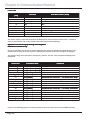
Input
De scription
Output
1
1
2
2
3
3
4
4
5
5
6
6
7
7
8
8
9
9
10
10
11
11
12
12
13
13
14
14
15
15
16
16
17
17
18
18
19
19
20
20
21
21
22
22
23
23
24
24
25
25
26
26
27
27
28
28
29
29
30
30
31
31
32
32
De scription
MNSNV102005Ver1.0
Page 31
SmartAVI, Inc.
3111 Winona Ave, Suite 101
Burbank, CA 91504
Tel (818) 565-0011 Fax (818) 565-0020
Email: [email protected]