1
3 awired
DIGITAL VIDEO RECORDERS
com
Premium Model: 3A-100
USER MANUAL
3aWired
9409 Lurline Ave,
Chatsworth, CA 91311
www.3awired.com
Phone 818.206.4882
Toll Free 877.848.9009
Fax 818.206.3495
Email [email protected]
3 awired
com
Notice
The information in this manual was current when published. The manufacturer reserves the right to revise and improve its products.
All specifications are therefore subject to change without notice.
Trademarks
3A-100 SERIES ® is a registered trademark of Formosa Industrial Computing Inc.
Microsoft, Windows, Internet Explorer ® are registered trademarks of Microsoft Corporation. Netscape, Navigator, Communicator ®
are registered trademarks of Netscape Corporation. Other brand and product names referred to in this manual are trademarks or
registered trademarks of their respective holders.
Trademarked names are used throughout this manual. Rather than place a symbol at each occurrence, trademarked names are
designated with initial capitalization. Inclusion or exclusion is not a judgment on the validity or legal status of the term.
Warning
To reduce risk of electric shock, do not remove cover. No user service-able parts inside. Refer servicing to qualified service
personnel.
Do not expose this appliance to rain or moisture.
Do not install this product in hazardous areas where highly combustible or explosive products are stored or used.
Severe impact or vibration may cause malfunction.
Do not move this product when 3A-100 SERIES is working.
Position it in an open space with flat surface, and also maintain at least 15 cm between the left and right sides of the body and
the wall.
The lightning flash/arrowhead symbol, within and equilateral triangle, alerts the user to the presence of a shock hazard within the
product’s enclosure.
CE Warning
This is a Class A product, in a domestic environment this product may cause
radio interference in which case the user may be required to take adequate
measures.
FCC Warning
This device complies with Part 15 of the FCC Rules. Operation is subject to
the following two conditions (1) this device may not cause harmful
interference, and (2) this device must accept any interference received,
including interference that may cause undesired operation.
Important information
Before proceeding, please read and observe all instructions and warnings contained in this manual. Retain this manual with the
original bill of sale for future reference and, if necessary, warranty service.
When unpacking your 3A-100 SERIES unit, check for missing or damaged items. If any item is missing, or if damage is evident,
DO NOT INSTALL OR OPERATE THIS PRODUCT. Contact your dealer or us for assistance.
i
3 awired
com
Table of Content
Chapter 1: Introduction
1.1 Main Features ------------------------------------------------------------------------------------------------------------------ 2
1.2 System Requirements --------------------------------------------------------------------------------------------------------- 3
Chapter 2: Getting Started
2.1 General Description ---------------------------------------------------------------------------------------------------------- 4
2.2 Physical Description---------------------------------------------------------------------------------------------------------- 4
2.2.1 3A-100 Panel -------------------------------------------------------------------------------------------------------- 5
2.3 Make the Physical Connection --------------------------------------------------------------------------------------------- 6
2.4 Running Mode of 3A-100 SERIES------------------------------------------------------------------------------------ 7
2.4.1 Use 3A-100 SERIES through Intranet ----------------------------------------------------------------------------- 8
2.4.2 Use 3A-100 SERIES through Internet ----------------------------------------------------------------------------- 8
2.4.3 Use 3A-100 SERIES via IrDA wireless controller--------------------------------------------------------------- 8
2.5 Power on 3A-100 SERIES---------------------------------------------------------------------------------------------- 9
2.6 Use Dynamic IP address for 3A-100 SERIES ----------------------------------------------------------------------- 9
2.6.1 Register 3A-100 SERIES
to registry server ------------------------------------------------------------------------ 9
2.6.2 Find the true IP address of APDR3400 SERIES ----------------------------------------------------------------------- 10
2.6.3 Browse and view the video ----------------------------------------------------------------------------------------------- 11
2.7 Use 3A-100 SERIES w
ith xDSL or Cable Modem ----------------------------------------------------------------- 11
2.7.1 Running PPPoE Protocol ------------------------------------------------------------------------------------------------- 11
2.7.2 Not Running PPPoE Protocol -------------------------------------------------------------------------------------------- 16
Chapter 3: Use 3A-100 SERIES under Network Mode
3.1 First Time Step-by-step Setup ----------------------------------------------------------------------------------------------- 18
3.2 Browse and view Live Video ------------------------------------------------------------------------------------------------ 19
3.3 System Configuration For First-time User --------------------------------------------------------------------------------- 23
3.4 Audio Functions --------------------------------------------------------------------------------------------------------------- 25
3.4.1 Audio Setting -------------------------------------------------------------------------------------------------------------------- 25
3.4.2 Use APDR-550 in Network Mode or ISP Mode -------------------------------------------------------------------- -------- 26
3.4.3 Operation ------------------------------------------------------------------------------------------------------------------------- 27
3.5 Using Dial-Up Network Connecting to 3A-100 SERIES ------------------------------------------------------------ 29
3.5.1 Step-by-step instructions to utilize Multi-Home function ----------------------------------------------------------------- 29
Chapter 4: Use 3A-100 SERIES Via IrDA Wireless Control or
Local Keyboard
4.1 IR Remote Controller --------------------------------------------------------------------------------------------------------- 31
4.2 How to operate 3A-100 SERI
ES via IR wireless Controller-------------------------------------------------------- 32
4.2.1 Using the Menus ------------------------------------------------------------------------------------------------------------ 33
4.3
4.4
4.5
4.6
Basic Operation using Keyboard -------------------------------------------------------------------------------------------34
Using the Menu----------------------------------------------------------------------------------------------------------------36
Main Menu---------------------------------------------------------------------------------------------------------------------37
System Setup-------------------------------------------------------------------------------------------------------------------37
4.6.1
Password Protect------------------------------------------------------------------------------------------------38
4.6.2
Video Parameters Setting--------------------------------------------------------------------------------------38
4.6.3
GPIO Setting-----------------------------------------------------------------------------------------------------42
4.6.4
PTZ Setup--------------------------------------------------------------------------------------------------------42
4.6.5
TCP/IP Setting---------------------------------------------------------------------------------------------------43
4.6.6
4.6.7
4.6.8
4.6.9
4.6.10
4.6.11
Account Setting--------------------------------------------------------------------------------------------------44
Audio Setting-----------------------------------------------------------------------------------------------------45
COM Ports Setting-----------------------------------------------------------------------------------------------46
System Information----------------------------------------------------------------------------------------------46
Date and Time Setting-------------------------------------------------------------------------------------------47
Registry Server Setting------------------------------------------------------------------------------------------47
ii
3 awired
4.7
com
4.6.12 Algorithm Setting------------------------------------------------------------------------------------------------48
4.6.13 Default Setting----------------------------------------------------------------------------------------------------48
Record Setup--------------------------------------------------------------------------------------------------------------------48
4.7.1
Record Schedule--------------------------------------------------------------------------------------------------49
4.7.2
Motion Detection-------------------------------------------------------------------------------------------------51
4.7.3
Pre-Alarm Function Setting-------------------------------------------------------------------------------------52
4.7.4
Playback-----------------------------------------------------------------------------------------------------------52
Appendix A: WCOMW Usage ------------------------------------------ I
Appendix B: Guide to revise firmware of 3A-100 SERIES -III
Appendix C: Troubleshooting ------------------------------------------ VII
iii
3 awired
com
Chapter 1: Introduction
3A-100 series Network DVR System is a
high performance digital video recorder built-in a mini web server with real-time
video capturing capability. The video is grabbed and compressed for faster transmission to your PC through 10/100Mbps Ethernet.
The video also can display through VGA output in local. Besides, 3A-100 series support digital recording function. It can
record/playback/browse video simultaneously and save video data by cycle recording to removable hard disk.
3A-100 SERIES supports full motion live video footage with its
corresponding audio through the Internet, Intranet connection.
Up to 16 cameras allow to be connected; 3A-100 SERIES deliver
real-time full-motion audio/video transmission to anywhere
anytime. All that is needed is an Internet browser and our proprietary plug-ins software. Attached video cameras can be remotely
controlled to swivel and zoom in and out, and the unit can be triggered to initiate certain events. 3A-100 SERIES is a
completely plug and play device getting up and running as soon as possible without the need for ongoing maintenance or custom
hardware/software configurations. Just via IR remote control, it’s such easy for users to setup 3A-100 SERIES without any
other PC operations. A sample c onfiguration is shown below.
Figure1.1.1 Simple 3A-100 SERIES Network Configuration
Note: APDR-3404/3408/3408/3412/3416 are the series of 3A-100 Network DVR System. We will use
correspond to all of 3A-100 series remote su
rveillance products in the following chapters.
3A-100 SERIES
The installation is easy: All you have to do is to plug the power and assign 3A-100 SERIES an IP address for Internet
connection. Then, you can view the video through your browser, Internet Explorer or Navigator, at any time, anywhere. It is perfect
for factory/office monitoring, ATM surveilla nce, children care, security system, tourism, sales presentation and more...APDR3400
SERIES is the new era of the network video transmission. It makes you see whatever you want easily!
1
3 awired
com
1.1 Main Features
Video & audio recording
Up to 16 camera inputs (color or B/W)
Up to 30 fps on each camera for local monitoring
Record / display / playback simultaneously
Built-in QUAD / Multiplexer functions for local monitoring
Local playback of recorded video on VGA or TV monitor
Remote playback from PC browser
Query recorded data by date, time & events
Control well known brand PTZ Cameras
High video quality and low data rate
Up to 200:1 video compression
Multiple video compression engines: H.263, JPEG, M-JPEG
Network
Dynamic IP support for Internet access
Direct Dial-up available
Backup
Removable Hard Drives
Optional CD Writer
Easy to use
Plug and play, non-Windows embedded real-time OS
Easy configuration via keyboard, IR Control, Home Page or RS-232 port
Standard web browser as the client application
Alarm function
Motion detection / Event trigger / Schedule / Pre-alarm recording
E-Mail & FTP alarm notification
Optional GPI/O for alarm control
Customization
Supports HTML file upload for home page customization
Supports FTP Server upload for customization
2
3 awired
com
1.2 System Requirements
Composite CCD camera, V8 or camcorder (NTSC or PAL standard)
The equipment for connecting to network:
1. Network mode: RJ-45 Ethernet network port connected to Internet and a public IP address
2. Others: RS-232 Port and a serial cable for connecting to host PC.
3. A VGA monitor for display.
PC for the configuration / browsing
1. Pentium II 350 CPU or above, desktop PC or notebook
2. 64 MB RAM or above
3. PCI VGA Card
4. Microsoft Windows 95/98/2000/ME/XP or above
5. Internet Browser (such as Netscape Navigator 4.0 or Microsoft Internet Explorer 4.0 or above)
- End of this chapter -
3
3 awired
com
Chapter 2: Getting Started
2.1 General Description
3A-100 SERIES is a plug and play network DVR system. The minimum PC system requirements for browsing and
configuration are described in section 1.2.
As 3A-100 SERIES transmit and record video/ audio data th
3A-100 SERIES via IR remote control.
rough Internet, Intranet, PSTN/ISDN, users also can operate
For Network Mode
For network mode, 3A-100 SERIES connects to a local area network or a network device by an Ethernet cable via the RJ45 port. Via Internet browser operation, users can view/ playback the recorded data. For network mode, there is a new
function called “Multi-homed”. This feature enable users to dial up to 3A-100 SERIES with modem and thus users can
use browser to access 3A-100 SERIES directly.
To get 3A-100 SERIES up and running, you have to set the IP
of 3A-100 SERIES under network ope
ration, please refer to chapter 3 for the configuration and usage.
For local IR remote control and keyboard operation
For local monitoring, Operating 3A-100 SERIES via IR re
mote control, connect 3A-100 SERIES “VGA Out” of the
VGA monitor and thus users can configure 3A-100 SERIES via IR
remote control, and then view local video and remote
video from the other 3A-100 SERIES all over the world at the same time.
We strongly suggest users to configure the system via IR remote control. Please refer to chapter 4 for setup procedures.
The following sections will introduce the features of 3A-100 SERIES. This informa
tion will help users to install 3A-100
SERIES for the first time. Users just follow the step-by step procedures to install your 3A-100 SERIES.
2.2
2.3
2.4
2.5
2.6
2.7
Physical Description
Make the Physical Connection
Running Mode of 3A-100 SERIES
Power on 3A-100 SERIES
Use Dynamic IP address for 3A-100 SERIES
Use 3A-100 SERIES with DSL or Cable Modem
2.2 Physical Description
Read the following information to be familiar with 3A-100
SERIES, making particular note of where the connectors and
indicators are located. This information provides a useful reference during the installation of the product into your networking
environment.
4
3 awired
com
2.2.1 3A-100 SERIES Panel
A.
A.
B. C. D.
B.C. D.
E. F. G.
E. G.
I. H.
H. I.
F.
A. Power cord connector and Power switch
The power cord and power switch are on the left side of the rear panel. Press ”I” to turn on the unit, press ”O” to shut down
the unit
B. Keyboard connector
Besides via IR remote control operation, users also can operate 3A-100 SERIES via local keyboard, the keyboard connector
is in the left side of 3A-100 SERIES rear panel.
C. USB connector
For 3A-100 SERIES, users need to connect the external IR
receiver to the USB port on the rear panel, and both USB
ports have the ability to be connected.
D. RS-232 serial port (COM1 and COM2)
Two 9-pin D-sub connectors provide RS-232 serial connection. COM1 Port is for configuration or for modem/ISDN Ta and
COM2 Port is for PTZ camera control.
E. Printer connector
Before power on 3A-100 SERIES, users need to attach the KeyPro to the 25-pin printer connector. You can find it in
3A-100 SERIES package.
F. Network connector
RJ-45 connector is for 100base T Fast Ethernet networks
G. MIC and speaker connector
MIC connector provides the function to input audio signal with a microphone. Speaker connector is in the right side of MIC
connector and provides audio output.
H. Video input
3A-100 SERIES allows a single video s
ource to be connected via the video input connector, and accommodates up to 16
video sources.
I. VGA Out connector
VGA Out connector provides composite video output to VGA Monitor.
5
3 awired
com
2.3 Make the Physical Connection
Before making 3A-100 SERIES to work, you shall make the physical connection as the following figure.
Follow instructions
included in this section to install 3A-100 SERIES into your ne
tworking environment. Each phase of the documented installation
procedure is summarized below:
6
3 awired
com
7
3 awired
com
Figure 2.4.1
LAN
3A-100 SERIES (Private IP)
2.4.2 Use 3A-100 SERIES through
Internet
1. If your environment is LAN ready and it is connected to Internet directly (Figure 2.4.2a). Assign a static public Internet IP to
3A-100 SERIES. Then read Chapter 3 for a step-by-step se
tup procedure for the usage of 3A-100 SERIES and read
Appendix B for changing running mode and configuration.
Figure 2.4.2a
LAN
Internet
2.4.3 Use 3A-100 SERIES via IR Remote Control
Not only connecting via Network, users can also use 3A-100 SERIES via IR remote control, please refer to Chapter 6 for
the usage. (Figure 2.4.5)
8
3 awired
com
Figure 2.4.3
Video
Cable
VGA Monitor
2.5 Power On 3A-100 SERIES
Before power on 3A-100 SERIES, you should check the followings:
2.5.1
Apply correct AC voltage to the internal power supply. The AC power input range is 100-240 volts, 50-60 Hz.
2.5.2
Connect the appropriate video inputs to the unit. Depends on the composite video standard used at your local area,
3A-100 SERIES automatically detects NTSC/PAL video when
power up. If you did not apply video signals when power
up, it will set to default value that is NTSC standard.
2.5.3
3A-100 SERIES is set to Network Mode after power up by
3A-100 SERIES, read Appendix B and follow a step-by-step setup
Modem/RS-232 running mode.
default. If you want to change the running mode of your
procedure for the installation to change to ISP mode or
Now, 3A-100 SERIES has completed the st
artup procedure and is ready. Before you can access it, you have to configure
3A-100 SERIES according to the running mode of 3A-100 SERIES. The defau
lt Mode of 3A-100 SERIES is under
Network Mode. Refer to Appendix B. to change running mode and configure 3A-100 SERIES under Network Mode,
ISP Mode, or Modem/RS-232 Mode accordingly. But for VP-310 users, we strongly suggest you to configure the running
mode via IrDA wireless controller.
2.6 Use Dynamic IP address for 3A-100 SERIES
If the IP address assigned to 3A-100 SERIES is static, us
ers can visit 3A-100 SERIES by this IP directly. If it’s
dynamic, 3A-100 SERIES provides users a way to register the system to a registry server. Then users just visit this
registry server and find the IP of 3A-100 SERIES.
2.6.1 Register 3A-100 SERIES to registry server
1.
On the left side of “advance setting” page, click “System Configuration” and you will have a page to configure system
parameters.
2.
Scroll down the page and find “Set IP Registry Host IP Address & Path ” setting and fill in the items, including
“Registry Host IPAddress ”, “Registry Host Ports”, “Registry Host Path” and choose if users can view the IP address
directly in registry server as figure 2.6.1.
3. After setting these registry server parameters, click “Done” to save the setting value.
9
3 awired
com
Figure 2.6.1
2.6.2 Find the true IP address of 3A-100 SERIES
1.
Please enter the registry host homepage first;
http://registry.nfic.com.tw/registry.htm . (Figure 2.6.2)
the
default
IP
address
of
registry
host
Figure 2.6.2
2.
Users can choose search by MAC ID (Ethernet Address) or search by name to find their own 3A-100 SERIES IP
location. Besides, users can browse all records in this registry server to find the IP address of their own 3A-100
SERIES. (Figure 2.6.3)
Figure 2.6.3
10
is
3 awired
com
Note: 1. For dynamic IP, users must check the IP address for the registry host
to find out the assigned dynamic IP.
2. DNS IP address must be correctly configured for 3A-100 SERIES to
register itself to a registry server.
2.6.3 Browse and view the video
Users can view the live video by click the IP address now, a nd the operations of ISP mode are the same as Network mode.
2.7 Use 3A-100 SERIES with DSL or Cable Modem
Users can connect 3A-100 SERIES to a DSL or Cable Modem via an Ethernet cable to the RJ-45 port of 3A-100
SERIES, as they will do to their PC. Since 3A-100 SERIES
does not support PPPoE, users have to check out if their
DSL/Cable Modem running PPPoE. Each phase of the documented installation procedure is summarized below:
2.7.1 Running PPPoE Protocol
2.7.2 Not Running PPPoE Protocol
2.7.1 Running PPPoE Protocol
For DSL or Cable Modem running PPPoE, since 3A-100 SERIES does not support PPPoE,
an external device is required.
The most common device is a Cable/DSL router with built-in NAT function that supports PPPoE. The configuration is as the
following figure.
3A-100
PC
If users connect 3A-100 SERIES via DSL
the device.
DSL/Cable
DSL/Cable
Modem
Router
PC
/Cable modem over PPPoE protocol, please follow the following steps to install
1. For static IP case:
When connecting 3A-100 SERIES via DSL
/Cable modem over PPPoE protocol, if a static IP address is assigned for
3A-100 SERIES, users have to set DHCP server, IP forwarding
(or Virtual Server) function, but don’t set registry server.
After setting these parameters, users can view the video from 3A-100 SERIES via this static IP address directly.
Note: About DHCP, IP forwarding, Virtua l Server parameters setting, please
refer to the following explanation.
11
3 awired
com
2. For dynamic IP case:
If 3A-100 SERIES is assigned a dynamic
IP via DSL/ Cable modem over PPPoE protocol, please make sure the devices
are all installed and the following settings are completed. In the following section, we will use Lemel LM-CAS1040 IP
sharing hub as an example to explain how to install an IP sharing hub and use 3A-100 SERIES via DSL/ Cable Modem.
A. DHCP Server Setting
B. IP Forwarding Setting
C. Registry Server Setting
A. DHCP Server Setting
IP sharing hub has two portions. Configure WAN portion in PPPoE to connect with DSL Modem. Connect Cable/xDSL to
the WAN port of the router and connect 3A-100 SERIES to its LAN port.
Note: A 10/100 Mbps LAN port is require d for connecting 3A-100 SERIES.
Since most of the DHCP of Cable/xDSL router will not always assign the same IP to the same device, a static private IP
must be reserved for 3A-100 SERIES.
Re-configure the range of private IP address of DHCP function to avoid conflict with 3A-100 Series’ default IP or you
can make a reserved private IP to 3A-100 SERIES.
For example:
1. Default IP address of 3A-100 SERIES is 192.168.10.10. In order to set it to our proposed IP address of 192.168.1.7,
please use WCOMW software tool to do it. Please refer to Appendix B for detail information.
2. After modify 3A-100 SERIES IP succe
ssfully, please connect a PC on LAN port 2 of the IP sharing router and set its
IP address to 192.168.1.20, subnet mask 255.255.255.0. Then bring up browser and access 192.168.1.7 to enter 3A-100
SERIES main page.
3.Click “Advance setting” at the bottom of 3A-100 SERIES homepage, then click “
the following window.
system configuration” to bring up
4. Traverse down the screen to set “Registry Host IP” as “ registry.nfic.com.tw” and “register HTTP port” keeps blank.
“Registry Host Path” remain as “cgi”. Please refer to Fig 2. Then click “OK” to save the values. This will make 3A-100
SERIES reboot. Wait for 40 seconds.
B. IP Forwarding Setting
12
3 awired
com
Set the IP Forwarding function to forward the IP that requests standard HTTP port 80 to the reserved IP address.
This will make router forward HTTP requests to 3A-1 00 SERIES. Configure the sta
ndard FTP port 21 mapping to
3A-100 SERIES also if there is a need to remote access the FTP function of
3A-100 SERIES. Assign 3A-100
SERIES a static private IP and change TCP/IP port of 3A-100 SERIES to some value other than 80.
For example:
After 3A-100 SERIES reboot successfully, access
http://192.168.1.7/usyscfg.htm from your PC browser as the
following figure and change HTTP port to “8001”. The “Enable Register Server” field should be “Disabled”. Then click
“OK” again to save the value. This will reboot 3A-100 SERIES again.
Note: Customer can set up his or her own registry server by visiting the “usyscfg.htm” page to enable this function within an
3A-100 SERIES. Under this situation, the registry server IP
address is customer’s own public IP of that 3A-100 SERIES.
C. Registry Server Setting
1. Power on ADSL and IP sharing router, wait for one-minute connection time. Check LED lights on these two devices to
see if they are both OK. Please refer to manufacturer’s user manual for proper LED indications.
2.
Connect a client PC from external world (NOT under the same LAN segments of IP sharing router) to Internet. Client
PC will have to visit http://registry.nfic.com.tw/registry.htm to find 3A-100 SERIES regist
ry and then access real IP
from there.
3.
Click “Browse All records” to find 3A-100 SERIES IP address. You can also search for the MAC ID you want.
4.
Find the MAC ID of the registered 3A-100 SERIES on
the list and map to the real IP to access 3A-100 SERIES
home page. You can see the port number “8001” that was set on previous section, was attached behind the real IP.
5.
Real time videos of 3A-100 SERIES should be able to show up on the screen if everything is OK.
Note: About registry server usage, please refer to section 2.6 to know how to find the real IP address of 3A-100 SERIES via
browsing registry server.
Installing IP sharing Hub (Lemel Model LM-CAS1040)
After users finish setting 3A-100 SERIES, users can start to install IP sharing hub. In the following case, we use Lemel
Model LM-CAS1040 IP sharing hub as the example, users just follow step-by-step procedures to install Lemel LM-CAS1040.
For other IP sharing hub users, please check their own user’s manual to finish the procedures.
Cabling:
1.
Connect the WAN (Internet) port of LM-CAS1040 to ADSL router LAN port.
13
3 awired
2.
com
Connect a PC with LAN card installed to one of the LAN ports of LM-CAS1040.
Configuration:
For PC side
1. Make sure your PC is equipped with LAN card and TCP/IP functions successfully.
2. Set TCP/IP property as “Getting IP Automatically”.
For LM-CAS1040 side
1. Bring up browser on PC side and access LM-CAS1040 configuration page at “192.168.1.254”.
For Global Port
1. Select “Global Port” on left side of the screen to get the following window.
2.
Select “PPPoE (DSL dynamic mode)”.
3.
Key in username and password of your ISP account.
Note: Some ISP may drop the dial up ADSL link daily if the link was there all the time. Check the “Auto-reconnect “ box on the
following figure for re-dial after the link is disconnected.
Check here for
automatic
reconnection
after ADSL link
dropped.
For Local Port
14
3 awired
com
1.
Make changes to “Start IP Address” to avoid conflict with 3A-100 SERIES IP. For example, when start IP address
set at 192.168.1.1, this means when network devices connect to LAN portion of LM-CAS1040 requesting for DHCP to
get their IP automatically, they will be assigned IP a ddress starting from 192.168.1.1 with a maximum to 192.168.1.128.
2.
If 3A-100 SERIES IP is set among any of these values, it
recommend start IP address is from 192.168.1.10.
will be chances to conflict with some other device. The
Recommend change
here to 10,then click
“ SAVE”
Virtual Server
1.
1.“Advanced Setup”
“ Virtual Server “ to bring up the following window.
Select HTTP (TCP80)
Click here
Key in 7
Key in 8001
Click here to add into server list
2.
Click “ By Port” .
3.
Select HTTP (TCP80) from the “ Application (port)” list.
4.
Key in “ 8001” into port number field.
5.
Key in 192.168.1.7 to Local Server IP address field.
6.
Click “ ADD” to add a local server of IP 192.168.1.7 with TCP port 8001 into the list.
Network Status:
15
3 awired
com
1.
Select “Network Status” -> “WAN IP status” to bring up Fig 7. This screen gives you indications of the outgoing ADSL
network status. When connection is built successfully, you can see the “PPPoE connection time”, ”IP Address”,
“Subnet Mask”, “Gateway”,” Primary” and “Secondary” DNS Server etc….
2.
If the ADSL connection is fail, you will NOT get the above data on 2.2.6.1 and there will be “NOT CONNECTED” in
the “PPPoE connection time” field. Then you will have to check cabling between ADSL modem and IP sharing router,
ADSL ISP account and password etc…
Session List:
1.
2.
3.
Select “Network Status”
“ Session List” to see network activities as the following figure.
If there are connections from outside world or inside local LAN, their IP addresses and port numbers will be
shown on the list.
This finishes IP sharing router configuration!
2.7.2 Not Running PPPoE Protocol
For DSL or Cable Modem not running PPPoE, users are free to connect 3A-100 SERIES with
without any other device.
xDSL/Cable Modem directly
1. For static IP case:
If a static public IP is assigned to the xDSL/Cable Modem account, just assign this IP to 3A-100 SERIES as the following
figure.
DSL/Cable
Modem
3A-100
16
3 awired
com
2. For dynamic IP case:
If the IP is dynamic, i.e. it is different for each time you dial up, set the IP to be 255.255.255.253. This will make 3A-100
SERIES request an IP from DHCP server every time it is turned on.
And since this IP is dynamic, users have to setup the registry server parameters for register the current IP to registry server.
Users then can find their 3A-100 SERIES on the registry server. Please reference chapter 3 for instructions.
- End of this chapter -
17
3 awired
com
Chapter 3: Use 3A-100 SERIES Under Network Mode
3.1
First Time Step-by-step Setup
For first time startup, 3A-100 SERIES is set to default valu
3A-100 SERIES are as following.
Running Mode
Network Mode
User’s Name
WEBMONITOR
User’s Password
OYO
Administrator’s Name
WEBMONITOR
Administrator’s Password
OYO
Custom Modem Init String (COM1) Nil
115200
COM1 Baud Rate (bps):
9600
COM2 Baud Rate (bps):
Enable
COM2 Hardware Flow Control
H.263
Video Encoding Algorithm
320x240
Set Video Resolution
Nil
Camera Control Device
120
Camera Control Timeout (Sec.)
Brightness
50
Contrast
50
Saturation
50
50
Hue
Quality
80
Compression Boost
None
Mirror Horizontally
Unchecked
Mirror Vertically
Unchecked
Auto Gain Control
Unchecked
Automatic
Unchecked
Mirror Horizontally
Unchecked
Mirror Vertically
Unchecked
MAX connections for this camera 0
MAX bandwidth for this camera 0
(Bytes/sec)
MAX bandwidth of each connection 0
for this camera (Bytes/sec)
Audio Source
1
Microphone Gain
50
Speaker Volume
50
Microphone Control Timeout
0
Speaker Control Timeout
60
IP address
192.168.10.10
DNS IP address
0.0.0.0
Gateway IP address
0.0.0.0
Sub net mask
255.255.255.0
Motion Detection
Enable
Motion Detection Sensitivity
50
Running Mode
Network Mode
18
e when it is delivered from factory. The default settings of
3 awired
com
User’s Name
Password
Registry Server
Register HTTP Port
Registry Host Path
Visibility in Registry Server
Alarm Status (GPI 1/2/3/4)
Time Stamp
Time Stamp Format
Send Mail
FTP Upload
webmonitor
oyo
http://www.registry.nfic.com.tw/
registry.htm
Nil
cgi
Listed on Registry Server
NO
Low center
MM/DD/YY
Disable
Disable
To get your VP-400 series network DVR system up and runningon an Ethernet network, please follow these instructions:
1. Connect the video camera(s), the microphone, and the speaker to 3A-100 SERIES
a. Connect the video output of your camera(s) to 3A-100 SERIES port(s) using standard 75-ohm coaxial video cable,
terminated with a BNC-connector.
b. Connect the microphone to MIC port and connect the speaker to Speaker port of 3A-100 SERIES.
Note: 3A-100 SERIES can auto-sense the presence and the standard of
video sources (NTSC or PAL). But be sure that all video sources are the
same standard.
c. Make sure the network cable (RJ45) connect to the socket marked “LAN” on the back panel of 3A-100 SERIES and the
other end to a 10/100Mbps port of a hub of this local area network. (Figure 3.1.1)
Figure 3.1.1
Ethernet (IP address: 192.168.10.xxx)
Ethernet (IP address: 192.168.10.10)
2. Connect the AC power cord to 3A-100 SERIES
a. Power on cameras first then power on 3A-100 SERIES
and 3A-100 SERIES will start to boot. It takes around 30
seconds. When you hear a long beep sound, it means 3A-100 SERIES is ready.
b. Now, 3A-100 SERIES has completed the startup procedure and is ready. Please see the following section to browse and
view the live video.
3.2
Browse and View Live Video
The default IP address of 3A-100 SERIES is 192.
168.10.10. If you need to use 3A-100 SERIES under
Network mode, your 3A-100 SERIES and PC must be in t
he same LAN. There are two ways to solve this
problem. The first one is to change the IP address of 3A-100 SERIES and the second one is to change the IP
address of the host PC. To use the second method, fo llow Step 1 to Step 4 preparing to connect to 3A-100
SERIES. When the IP address of 3A-100 SERIES is dynam
ic, user should set these parameters for 3A-100
SERIES to register itself to a registry server, thus users can choose search by MAC ID or name to find their own
19
3 awired
com
3A-100 SERIES IP location. Besides, user
s can browse all records in this registry server to find the IP address
of their own 3A-100 SERIES.
1. To browse 3A-100 SERIES under the default Network Mode, go to “
Figure 3.2.1
2. Choose “TCP/IP” and go to “Properties”
Figure 3.2.2
3. Change IP address of the host PC to: 192.168.10.20
4. Change Subnet Mask of the host PC to:
Figure 3.2.3
255.255.255.0
20
Network” on “Control Panel” of the host PC.
3 awired
com
Note: Remember the original IP address and Subnet Mask. When the configuration of 3A-100 SERIES is finished, you
need to reset the host PC to these original values.
And reboot the host PC.
5. Run a web browser and connect to http://192.168.10.10 (If you have changed the IP address of 3A-100
SERIES, it shall be the new IP address). When it is connected, you will see a login dialog-box. Enter the default
Administrator’s name “webmonitor” and Administrator’s password “oyo”. Click “OK” button. Then you will see
the home page of 3A-100 SERIES.
Figure 3.2.4
6. In case you didn’t install Plug-ins program that comes with a diskette in APDR3400 SERIES package. You will see the
screen as follows.
Figure 3.2.5
7. Click on anyone of four video window areas. You will see a dialog popup.
Figure 3.2.6
21
3 awired
com
8. Click ‘Download LVETUP.EXE’ to downl oad plug-in program from 3A-100 SERI
ES then you will see the following
screen.
9. Start downloading plug-in and install it. After finishing the jobs, you shall see the following screen.
Figure 3.2.7
10. Instead of installing plug-in program in your PC. You can click “View Video Without Plugins” on the left side of
home page, and key in user ID and password again then you will view the live video by using Java applet. Live view Java
applet utilize JPEG image snapshot from 3A-100 SERIES.
Figure 3.2.8
Figure 3.2.9
22
3 awired
com
11. Click ‘Camera 1’ link to switch to the signal camera view screen
Figure 3.2.10
12. On the right side of the page, you can see some links. You can click them and operate your 3A-100 SERIES.
13.
3.3
Please see the following sections for advance configuration.
System Configuration For First-time User
1. Run a web browser and connect to http://192.168.10.10. (If you have changed the IP address of 3A-100 SERIES, it
shall be the new IP address). When it is connected, you will see a login homepage. Enter the default Administrator’s name
“webmonitor” and Administrator’s password “oyo”. Click the “OK” button.
2. Then you will see the home page of 3A-100 SERIES. (You can
3A-100
SERIES.)
Figure
3.3.1
Figure 3.3.2
23
also see live video when cameras are connected to
3 awired
com
3. Scroll down the above page. On the bottom of this page, Click “Advance Setting” then you will see a brand new web
page. On the left side of this web page, choose “System Configuration” to do the configuration.
Figure 3.3.3
System Configuration
4. Input IP Address, Gateway IP Address, Subnet Mask, and DNS IP Address in “TCP/IP Setting” segment. About dynamic
IP address setting, please refer to chapter 2.6.
24
3 awired
com
Note: DNS IP address must be assigned if a domain name other than an IP address is used as a server’s address in the
following fields: “Registry Host Address” in System Configuration Page, “E-Mail Server” in E-Mail setting, and
“FTP Server” in FTP Upload setting.
Figure 3.3.4
5. You may change account name and the password. In “ Account Setting” segment, input User Name, User Password,
Administrator’s Name and Administrator’s Password.
Note1: 3A-100 SERIES provides two layers protection. You can
limit users with User Name and Password to login
3A-100 SERIES. To set the configuration of 3A-100
SERIES, you must have Administrator’s Name and
Administrator’s Password.
Note2: Keep the password carefully and remember it. Once you forget the password, you can reset 3A-100 SERIES.
The user name and password will be reset to the default values. It also means you have to set the configuration
again.
Remember to change the IP address of your PC to make sure that 3A-100 SERIES and your PC are on the
same network.
3.4 Audio Functions
1.Start visit 3A-100 SERIES from Home Page
2. Click ‘Camera 1’ link to view the first camera.( Figure 3.4.1 )
25
3 awired
com
Figure 3.4.1
Click “Camera 1+Audio” link to the page of both the first video and audio.
The Audio operation interface is as follows:
Bandwidth used
Volume Level
Microphone ON/OFF
Save audio data to file
Note: The audio function of 3A-100 SERIES supports two-way audio
transmission but only one-way audio data from 3A-100 SERIES to
PC can be recorded.
3.4.1 Audio Setting
On the left side of Advance setting page, click “Audio Setting” and you will have prompted out Figure 3.4.1.
26
3 awired
com
Figure 3.4.1
Chose a certain audio source to set the parameters, you can set following parameters:
1. Audio Source:
Select an audio input and output source to set parameters
2.
Microphone Gain
Set the value of GAIN for Microphone of Audio input in 3A-100 SERIES.
3.
Speaker Volume
Set the value of GAIN for Speaker of Audio output in 3A-100 SERIES.
4.
Microphone Control Timeout
At a given time, there is only a user can control the operation of Microphone connected to 3A-100 SERIES. Once
users get the control right, they can select the source (1,2,3,4) to control but only one source can be controlled at any
time. This timeout value is the maximum period in seconds that user can own the right without any bother. In this
period, nobody can rob the control right except the administrator. Once timeout, anybody can ask to gain the control
right of Microphone excluding the original owner.
5. Speaker Control Timeout
At a given time, there is only one user can control the operation of Speaker connected. The rule of timeout and grant
of control right is the same as the one of Microphone Control described above.
3.4.2
3A-100 SERIES audio recording function in Network Mode
VP-400 series supports single channel audio recording function, and users just follow the institutions to setup.
1. Before setting up 3A-100 SERIES audio recording function,
please make sure that the microphone and speaker have been
connected to “MIC” and “Speaker” ports.
2. On the left side of advance setting home page, click “Record Schedule” and you can enable or disable “Record Schedule” of
3A-100 SERIES.
3. Choose the certain schedule that users want to range, and check “Stream Video Setup”. Users can enable or disable audio
recording function.
4. If users enable the fungAfter pressing “Done” button to save the recording schedule, then 3A-100 SERIES will record the
certain video and audio data following the schedule.
Note: 1.3A-100 SERIES only supports single-channel audio recording.
2. About the usage of audio recording, please refer to Chapter 3 on CD disk with 3A-100 SERIES standard package.
27
3 awired
com
3.5.1 PTZ Operation
If you have equipped a camera control device with 3A-100 SERIES, you can use th
camera.
e camera control interface to control a
1.Start visit 3A-100 SERIES from Home Page
2. Select the proper camera control device in the “system configuration” page (refer to section 3.3 in the user
manual). Then click certain camera link to view the screen, and click “Camera Control” link in the right side of the
page.
3. You can use UP/DOWN/LEFT/RIGHT to make the camera move a little bit toward the direction you clicked. Also
you can use ZOOM and FOCUS buttons to zoom or focus in and out. Due to the network transmission delay, the
video may not response as soon as you click the button. (Figure 3.5.3)
Figure 3.5.3
4. If the device has built in preset function, you can use the buttons described above to move the camera to where
you want and use Preset button to make the camera control device to remember the position. After presetting,
you can use Recall buttons to make the camera move to a preset position.
5. Click on the buttons on the Pan/Tilt, Zoom blocks will force the camera to operate following the corresponding commands.
But please be patient to allow enough time for the video to transmit back from the remote side. Don't click the buttons too
fast or it may be difficult to get the right view you want remember "click and wait" is the most efficient operation.
6. The 6 preset buttons allow you to tell the camera to remember 6 positions that you prefer. When the camera is located at
some positions and you click the preset button, this position will be kept inside the camera's memory. After a while, if you
move the camera to another position and you want it to move back to the previous preset position, just click the
corresponding recall button and it will move back to that position automatically. This function is handy when it is difficult to
adjust the camera to the right position. You can preset it locally and then recall it remotely. But one thing bad is that after
power off the camera, previous preset values will be lost. In this case you have to do the presetting from the beginning.
28
3 awired
com
3.6 Using Dial-Up Network Connecting to 3A-100 SERIES
Now, 3A-100 SERIES supports a new function called
“Multi-homed” is supported. This feature enable users to
dial up to 3A-100 SERIES with modem and thus user
s can use browser to access 3A-100 SERIES. This
feature is added to Network Mode of 3A-100 SERIES.
That is, users can connect to 3A-100 SERIES
through Ethernet or modem at the same time. It's useful specially when users have no network or Internet and still
want to remotely access 3A-100 SERIES.
For 3A-100 SERIES, users can both browse the image thr
time as the
ough Internet and via multi-home function at the same
following figure.
3.6.1 Step by step instructions to utilize Multi-Home function
A. Prepare 3A-100 SERIES ready for Dial-In
1. Check the FW 3.045/5.045 (or later) version for 3A-100 SERIES.
2. Make sure 3A-100 SERIES is running under Network Mode.
3. Connect 3A-100 SERIES with a modem on its COM1 port.
4. In general, there's no need of setup modem driver for the modem that is used to accept incoming call. But if you
experience trouble in call setup of modem, try to setup driver for the modem as the following steps indicate.
5. To setup modem driver to 3A-100 SERIES,
SERIES.
connect a RS-232 cable between your PC and 3A-100
6. Install the modem driver coming from the manufacturer of the modem onto your PC ( no need to attach modem to
your PC).
7. Run WCOMW (ver. 1.7 or later) on your PC, turn on 3A-100 SERIES.
8.When configuration menu is pop-up, press "5. Setup Modem". Choose "Modem" in "Tool" of WCOMW's menu and
select the driver you just installed and press OK. This will generate some text of the modem driver settings to
WCOMW.
29
3 awired
com
Figure 3.6.2
9. Press Enter, this will make the settings of modem driver configured to 3A-100 SERIES. Choose "Exit" to make
3A-100 SERIES continue to boot.
Figure 3.6.3
10. Remove RS-232 cable, and attach modem to COM1 port of 3A-100 SERIES. Now you have done the
modem driver setup to 3A-100 SERIES.
11. When 3A-100 SERIES is ready, it's ready fo
r connections coming from both Ethernet and modem.
B. Dial-up to 3A-100 SERIES
1. Click on the "Dial-Up Networking" folder at the top level of "My Computer", double-click "Make New Connections"
to build a new dial-up setting.
2. Open the property of the new connection and choose the type of protocol to be "PPP: Internet, Windows NT
Server, Windows 98".
3. Clear all the options of "Advanced options" and "Allowed network protocols" except "TCP/IP". That is, make sure
only "TCP/IP" option is checked in this page.
30
3 awired
com
4. Click "TCP/IP Settings" button. Specify the IP address to be "10.0.0.2".
You can use other IP as long as it is in the same group with “10.0.0.1”.
The “10.0.0.1” is fixed inside 3A-100 SERIES.
5. Check "Server assigned server address" in DNS setting. And make sure "Use IP header compression" and "Use
default gateway on remote network" are both UNCHECKED.
6. Click OK to finish the procedure.
7. Please set up the telephone number of 3A-100
SERIES, user name, and user password in “Dial-up
Network”. Then click “OK” to save the settings. The default user name and password are “webmonitor” and
“oyo.”
8. Now you can use this connection to dial-up to 3A-100 SERIES.
9.When you have dialed up to 3A-100 SERIES, use browser to
view the address "10.0.0.1" which is the IP address of
3A-100 SERIES on this dial-up connecti
on. Since this is only a point-to-point connection, users are limited to access
3A-100 SERIES site only.
- End of this chapter -
31
3 awired
com
Chapter 4: Using 3A-100 Series Via IR Remote Control or Local
Keyboard
4.1 IR Remote Control
Besides using 3A-100 SERIES under Network Mode, users can also operate 3A-100 SERIES via IR remote control or
local keyboard and the video will be displayed on the VGA monitor screen. Before operating 3A-100 SERIES via IR remote
control, please make sure that 3A-100 SERIES has connected to the VGA monitor via VGA Out connector.
To get 3A-100 SERIES up and running via IR
remote control, an IR remote control is require, users will find it in the
package of 3A-100 SERIES. The interface
of remote control is as following.
A
B
O
N
C
D
M
L
K
E
F
J
I
G
H
A. TV button
This button is no used for 3A-100 Series Network DVR System.
B. Menu button
Supplying main menu display function. When users press this button, it will display the main menu on the screen.
C. Cancel button
Supplying cancel and close function. When users press this button, it will close the menu in the setting menu and returns you to
the previous level.
D. Up/Down/Left/Right button
When pressing the remote control in the direction, users can control the directions of cameras or adjust the parameters of the
setting menu.
E. Speed/Play/Pause/Stop/Seek Backward/Seek Forward/Step Backward/Step Forward button
These buttons are only for 3A-100 SERIES playback function. They are no used for 3A-100 SERIES operation.
F. Number button
When pressing the number buttons, users can select the camera when multiple cameras are used.
32
3 awired
com
G. Contrast Setting buttons
When pressing “+” or “-” button of contrast setting, users can increase or decrease contrast values of the images from different
cameras on the monitor.
H. Bright Setting buttons
When pressing “+” or “-” button of bright setting, users can brighten or darken images from different cameras on the monitor.
I. Fn button
This button is not used.
J. Display button
This button is only used for 3A-100 SERIES to switch the display status.
K. Prev / Next Page button
In the setting menu, users can press Prev / Next page button to skip to the previous or the next page in the setting menu.
L. OK button
This button is used to store the setting values in the setting menu.
M. Keypad button
When pressing the button, it will pop up a keypad for users to input in the setting menu.
N. Mode Switch button
“Remote”, “Playback” and “Local” buttons supply users to switch the status of displaying. “Remote” button is no used for
3A-100 Series.
“Playback” is used for 3A-100 SERIES
to playback the recorded files. When pressing “Local”
button, users can view the live image immediately.
O. Display Status Switch
These three buttons supply the function to switch the mode of images displaying. Users can press “Single” or “Quad” buttons to
change the way to display on the screen. “In Turns ” button is no used for 3A-100 Series operation.
4.2 How to operate 3A-100 SERIES via IR remote control
Functions of 3A-100 SERIES under Network Mode, users can
also operate 3A-100 SERIES via IR remote control and
the video will be displayed on the VGA monitor screen. Before operating 3A-100 SERIES via IR
remote control, they have
to connect their 3A-100 SERIES as the following instructions:
1. Connect the video camera(s) to 3A-100 SERIES Network DVR System
Connect the video output of your camera(s) to 3A-100 SERIES Camera server port(s) using standard 75ohm coaxial video
cable, terminated with a BNC connector.
2. Connect the AC power cord to 3A-100 SERIES Network DVR System
After hearing one short beep sound, 3A-100 SERIES will star
t to boot. It takes around 30 seconds. When you hear a long
beep sound, it means 3A-100 SERIES is ready.
3 Connect the VGA monitor to 3A-100 SERIES Network DVR System
Before operating 3A-100 SERIES via IR remote control, pl
ease make sure that 3A-100 SERIES has connected to the
VGA monitor via “VGA Out” connector.
Note: When the IP address of 3A-100 SERIES is dynamic, user should se
these parameters for 3A-100 SERIES to register itself to a registr
server, please refer to Chapter 2.6 to register the IP address of 3A-100
SERIES.
t
y
4. Now, users can view the live video image on the VGA monitor screen and they can operate 3A-100 SERIES via IR
33
3 awired
com
remote control directly. (Figure 4.2.1)
Figure 4.2.1
Users can press number buttons to choose the video from different cameras displaying on the screen. And start to view the
image locally.
4.2.1 Using the Menus
There are some keys for users to operate the menus via IR remote control.
Use the Menus
When 3A-100 SERIES is working, users can press “
Menu” button to enter “System Setup” menu, users can press
Up/Down button to select the setting parameter, then press “Right” or “OK” button to enter the setting menu.
Enter the Menus
After pressing “Menu” and the system setup menu pop up, users can press Up/Down button to select the function, then please
press “Right” or “OK”
button to enter the next level setting menu or press “Cancel” button to exit the setting menu and go back to the view screen.
Operate the Menus and Change the setting Parameters
Users can select the setting values by pressing Up/Down button and change the setting value by pressing Left/Right button.
Then press “OK” to save the setting value or press “Cancel” to cancel the setting and go back to the previous level setting
menu.
For some cases, users also need to key in some characters via IR remote control. Users can press “Keypad” button to setting the
characters then press “OK” to save the setting value or press “Cancel” to cancel the setting and go back to the previous level
setting menu.
View the Previous/Next Page
In the setting menu, users can press Prev/Next page button to skip to the previous or the next page in the setting menu.
Exit the Menus
After changing the setting values, users can press “ OK” to save the setting value or press “Cancel” to cancel the setting and go
back to the previous level setting menu. Or users also can press “Menu” button to go back to the system setup menu directly.
Audio Recording Setup
1. Press “Menu” and select “Record Setup”. Select “Record Schedule” and press “OK” or “Right” button to enter the record
schedule list of 3A-100 SERIES setting.
2.After enter the schedule, please press “Next” button to enable or disable audio recording function. Then press “OK” button
to save the recording schedule, then APDR3400 SERIES will record the certain video and audio data following the schedule.
34
3 awired
com
Note: About the operation of 3A-100 SERIES IR remote control,
package.
please refer to CD disk with 3A-100 SERIES standard
4.3 Basic Operation via local keyboard
To get 3A-100 SERIES up and running via
operation is as following figure.
local keyboard, a keyboard is required. The interface of 3A-100 SERIES
2~13
1
14 15
16
17
18 19
1. Esc: Cancel
Provide cancel and close function. When pressing “Esc”, it will close current setting menu and returns to the previous level.
2. F1: Menu
Provide main menu display function. When users press “F1”, it will display the main menu on the screen, and press “Left/
Right/ Up/ Down” button to select, and then press “Enter” for confirmation.
3. F2: Playback
Press “F2” to enter playback list, and press “Up/ Down” button to select the recorded file, and then press “Enter” or “F5” to
play the video.
4. F3: Local
When pressing “F3”, users can view the live image immediately.
5. F4: Screen
Press “F4” to switch display setting from Single, Quad, 8 splits and 16 splits. Press “Up/ Down” button to select, and then
press “Enter” to make sure the selection.
6. F5:
(Play)
When pressing “F5”, the recorded data will start to play. Users also can press “F5” to skip the crash video and play next time
period continuously.
7. F6:
(Pause)
When pressing “F6”, users can pause the playing video.
8. F7:
(Stop)
When pressing “F7”, users can stop the playing video.
9. F8: Speed
35
3 awired
com
When pressing “F8”, users can switch the playing speed.
10. F9:
(Seek Backward)
When pressing “F9”, users can backward seek the video.
11. F10:
(Step Backward)
When pressing “F10”, users can backward the video frame step-by-step.
12. F11:
(Step Forward)
When pressing “F11”, users can forward the video frame step-by-step.
13. F12:
(Forward)
When pressing “F12”, users can forward seek the video.
14. S: Speed
The function is the same as “F8”.
15. D: Display
When pressing “D” in playback mode, users can view the status of video, GPI, Motion Detection, progress in bar chart at the
bottom of the screen.
16. Space: Step Backward/ Step Forward
When playback the video, users can press space bar to step backward or step forward seek the video.
17. Enter: Play/ Pause/ OK
This button is used to store the setting values in the setting menu. Besides, when playback the video, users can press “Enter” to
continue or pause the playing.
18. Up/ Down/ Left/ Right Button
When pressing these buttons, users can control the directions of cameras or adjust the parameters of the setting menu.
19. Page Up/ Page Down: Previous Page and Next Page
In the setting menu, users can press “Page Up/ Page Down” to change the setting menu page.
4.4 Using the Menu
There are some keys for users to operate the menus via IR remote control.
Use the Menu
When 3A-100 is working, users can press “
Menu” button to enter “System Setup” menu, users can press Up/Down
button to select the setting parameter, then press “Right” or “OK” button to enter the setting menu.
Enter the Menu
After pressing “Menu” and the system setup menu pop up, users can press Up/Down button to select the function, then please
press “Right” or “OK”
button to enter the next level setting menu or press “Cancel” button to exit the setting menu and go back to the view screen.
Operate the Menu and Change the setting Parameters
Users can select the setting values by pressing Up/Down button and change the setting value by pressing Left/Right button.
Then press “OK” to save the setting value or press “Cancel” to cancel the setting and go back to the previous level setting
menu.
For some cases, users also need to key in some characters via IR remote control. Users can press “Keypad” button to setting the
characters then press “OK” to save the setting value or press “Cancel” to cancel the setting and go back to the previous level
setting menu.
View the Previous/Next Page
In the setting menu, users can press Prev/Next page button to skip to the previous or the next page in the setting menu.
36
3 awired
com
Exit the Menu
After changing the setting values, users can press “OK” to save the setting
value or press “Cancel” to cancel the setting and go back to the previous level setting menu. Or users also can press “Menu”
button to go back to the system setup menu directly.
Audio Recording Setup
3. Press “Menu” and select “Record Setup”. Select “Record Schedule” and press “OK” or “Right” button to enter the record
schedule list of 3A-100 setting.
4.After enter the schedule, please press “Next” button to enable or disable audio recording function. Then press “OK” button
to save the recording schedule, then 3A-100 will record the certain video
and audio data following the schedule.
4.5 Main Menu
After bring up 3A-100 , you can press “
as Fig 4.5.2.
Menu” button to enter main set up menu
Figure 4.5.1
Figure 4.5.2
4.6 System Setup
You can use Up/Down button to select “ System Setup”, then press “Right” button to enter “System Setup” screen as fig 4.3.1
or press “Cancel” button to go back to previous screen.
37
3 awired
com
Fig 4.6.1
4.6.1 Password Protect
On the screen of fig 4.3.1, press “Right” button to enter “Password Protect” set up screen as fig 4.3.1.1.Please use “Keypad”
button to enter values for “Password”, “Auto Lock Time”(sec). Then press “OK” to save the values or press “Cancel” to go
back previous level.
Fig 4.6.1.1
4.6.2 Video Parameters Setting
1. Press “Menu” and select “System Setup”. Choose “Video” and press “Right” button to enter video configuration menu.
2. You can use “ Left” or “Right” button to modify the values or pressing “Prev” or “Next” button to browse different
configuration pages as shown on figure 4.5.1.2.
3.Then press “OK” to save the values or press “Cancel” to go back previous
menu.
38
3 awired
com
Fig 4.6.2
4. Setting general parameters :
Standard -- “AUTO”, 3A-100 will de
tect video input to this channel automatically.
It can be manually set as “NTSC”,
“PAL” or “SECAM”.
Frame Rate – The frame rate ranged from 1 to 30. You can set the frame rate
you want for each camera. But the total frame rate adds up to all cameras will be limited by overall system performance.
Frame rate 0 stands for maximum video refresh rate.
Brightness -- The higher value ,the brighter of the video
Contrast -- The higher value, the stronger contrast
Saturation -- The higher value, the more color saturation
Hue
-- The higher value, the higher hue
Quality -- Higher value, better video quality
Note: 1. The value of “ Quality” applies to all video sources. That of brightness, contrast, saturation and hue applies to the
selected camera only.
2. Please choose one global brightness value carefully among cameras attached and then set Gain values for each camera
individually.
Note: Higher value of quality level makes heavy data rate for both storage and transmission.
Compression Boost -- Users can select “None”, “Low”, “Medium” and “High” value to adjust the compression rate. The higher
compression boost , the lower video data rate . High compression may affect the video quality.
Auto Gain Control -- Check to enable auto gain control for this camera.
Gain Value -- Set gain value for this camera. The GAIN ranged from 0 to 100.
Mirror Horizontally -- Mirror the selected video viewing from left to right
Or right to left.
Mirror Vertically -- Mirror the selected video viewing up side down or down
side up.
Max connections for this camera -- Limit the maximum connections
allowed to access this camera.
Max bandwidth for this camera (Bytes/sec) -- Limit the maximum
39
3 awired
com
bandwidth in Bytes/second allocated to access this camera.
Max bandwidth of each connection for this camera (Bytes/sec) -- Limit the
maximum bandwidth allocated to each connection of this camera.
Click the “OK” button to make the new settings take effect.
Note: 3A-100 will not save the se
ttings if you didn’t click ”OK”.
5. Video input
This function is for setting video window position of camera inputs. Position 1 is at top left and position 16 is bottom right.
Default cameras are set at this sequence. You can modify it to change video window position of the cameras displayed on
VGA or TV screen.
Fig 4.6.3
6. PTZ Control
First page – Direction control. Please use “Up”, “Down”, “Left” and “Right” button to make the camera move a little bit
toward the direction you clicked. Press “OK” to save the values or press “Cancel” to cancel to go back previous menu. Press
“Next” to enter next page of PTZ camera control functions.
Second page – Zoom in / Zoom out control. Please use “Up” and “Down” button to zoom in or zoom out. Press “Prev” or
“Next” button to change pages. Other operations are same as before.
Third page -- Focus control. Please also use “Up” and “Down” buttons. Other operations are also the same as before.
Fourth page – Playing speed control. Press “Left” and “Right” button to adjust the playing speed. Other operations are also
the same as before.
Fifth page – Preset position recall. Press Number key 1 to 6 to recall the
camera to the preset position saved in memory .Other operations remain the same as before.
The last page – Preset position set up.Please use “Up”, “Down”, “Left” and “Right” button to move the camera to the
position you want and then press numeric key 1 to 6 to save this camera position data into memory.
4.6.3 GPIO Setting
You can choose the item “ GPIO” from Fig 4.3.1 to enter this page. The Alarm Status shows the "NO"(Normal Open) or
"NC"(Normal Close) state of the GPIs. You can also control the outputs of GPOs by selecting the state of each GPO and
clicking the output bottom. The output of the GPOs will latch on the state you selected.
40
3 awired
com
1. Press “Menu” and select “System Setup”. Choose “GPIO” and press “Right” to enter the setting of GPIO setting.
2.
2. Users can adjust “N.O.” or “N.C.” status in GPI setting and set “ON” or “OFF” in GPO status by pressing “Left” or “Right”
button. Then press “OK” to save the setting value or press “Cancel” to cancel the setting, go back to the previous level setting
menu.
4.6.4 PTZ Setup
1. Press “Menu” and select “System Setup”. Choose “PTZ Setup” and press “Right” button to enter the setting of PTZ camera
control setting.
Fig 4.6.4
2. The supporting PTZ devices are listed on the screen after Choosing “PTZ Device”. Please use “Up”, ”Down” button to
select the device type. You shall check which camera number that device hooked to (from 1 to 16) and the timeout of
exclusive control right. Only one user can control the camera at a time. The time-out value is in seconds. During this period,
only the administrator can take over the control right . After the time expired, the exclusive control right will grant to other
users.
3. Then press “OK” to save the setting or press “Cancel” to go back to previous level.
4.6.5 TCP/IP Setting
1. Press “Menu” and select “System Setup”. Choose “TCP/IP” and press “Right” button to enter the setting of TCP/IP
address.
2. Input IPAddress, Gateway IPAddress, Subnet Mask, and DNS IPAddress in “ TCP/IP Setting” as Fig 4.6.5. Users can press
the numeric keys to enter the numbers and then press “OK” to save the setting value or press “Cancel” to cancel the setting
and go back to previous level.
Fig 4.6.5
4.6.6 Account Setting
41
3 awired
1.
com
Press “Menu” and select “System Setup”. Choose “Account” and press “Right” button to enter the setting of users’
account.
2. Please select the “Account” field to set up Admin Name, Admin Password, Us er Name, User Password and set more user
accounts as followings.
3. Press “Up” or “Down” button to move cursor and then press “Right” button to select one of Admin Name, Admin Password,
User Name, User Password items for configuration.
4. Enter alphanumeric characters by pressing “Keypad” button or select the characters by pressing “Up”, “Down”, “Left”, and
“Right” button; then press “OK” to save the characters or press “Cancel” to exit the keypad and return to previous menu.
A maximum of 256 pairs “user name” and “pass word” can be set up.
For example, enter “USER” and “1234” as the name and password of User 1 and enable camera 1 and 3. Later you can connect to
3A-100 and login in using “
USER” and “1234” as user 1. After logging in, only camera 1 and camera 3 will be displayed. If
the name and password are left blank, this entry will not be used. If the name and password fields content are both the same word
---“BLANK”, user logs in without entering password will use this account.
Enabling “PTZ” will grant user’s right to do camera control . Enabling “Audio” will grant the right for audio operation.
4.6.7 Audio Setting
1. Press “Menu” and select “System Setup”. Choose “Audio” and press “Right” button to enter Audio setting as Fig 4.6.7.
Figure 4.3.7
2. You can increase or decrease microphone and speaker gain by pressing “ Left” or “Right” button and then press “OK” to save
the value or press “Cancel” button to go back to previous menu.
3. Set Microphone Timeout
At a given time, there is only a user can control the operation of Microphone connected to 3A-100. Once users get the
control right, they can select the source (1,2,3,4) for microphone input. But only one source can be controlled at any time.
This timeout value is the maximum period in seconds that user can own the right without any bother. During this period,
nobody can interrupt the control right except administrator. Once timeout, anybody can ask to gain the control right of
Microphone excluding the original owner.
4. Set Speaker Control Timeout
At a given time, there is only one user can control the operation of Speaker connected to 3A-100. The rule of timeout and
grant of control right is the same as the one of Microphone Control described above.
4.6.8 COM Ports Setting
42
3 awired
com
1. Press “Menu” and select “System Setup”. Choose “COM Ports” and press “Right” button to enter COM Port screen.
Fig 4.6.8
Note: If the PTZ camera is controlled by RS-485 or RS422 interface, please disable “COM2 hardware flow control” in COM
Port Setting.
2. Please use “Left” or “Right” button to modify the values and then press “OK” to save or press “Cancel” to go back previous
menu.
4.6.9 System Information
Press “Menu” and select “System Setup”. Choose “System Info” and press
“Right” button to enter the page of system information. Just show some
information inside 3A-100 as Figure 4.6.9.
Fig 4.6.9
4.6.10 Date/Time Setting
1. Press “Menu” and select “System Setup”. Select “Date/Time” and press “Right” button to enter the menu of Date/Time
setting.
Figure 4.6.10
2. Please use “Left” or “Right” button to modify the values and then press “OK” to save or press “Cancel” to go back previous
menu.
43
3 awired
com
4.6.11 Registry Server Setting
1. Press “Menu” and select “System Setup”. Select “ISP ” and press “Right” button to enter the menu of ISP setting.
2. When the IP address of 3A-100 is dynamic, please set th
e parameters for 3A-100 to register itself to a registry
server, thus user who wants to access this 3A-100 can find it
by visiting the yellow page provided by the registry server.
Contact with your local distributor for configuring these parameters. The IP address of default registry host is
http://registry.nfic.com.tw/registry.htm, and the default registry host domain name is Null, and the value of registry host
path is “cgi”. Please visit http://registry.nfic.com.tw/registry.htm to query or browse current registered 3A-100 units on
Formosa’s registry server.
4.6.12 Algorithm Setting
1. Press “Menu” and select “System Setup”. Select “Algorithm” and press “Right” button to enter the menu of algorithm
setting.
2. You can select video algorithm as H.263, JPEG, or M-JPEG format by pressing “ Left” or “Right” button and then press
“OK” button to save the value or press “Cancel” button to go back previous menu.
3. Values of video dimension can be 320x240 or 640x480 format.
4. After saving the values, APDR- 3400 will reboot to the new settings.
4.6.13 Default Setting
1. Press “Menu” and select “System Setup”. Select “Default Setting” and press “Right” button to restore 3A-100 default
settings.
2. Press “OK” to save 3A-100 default settings now or press “
Cancel” button to go back to previous level .
4.7. Record Setup
Enter “Menu” screen and select “Record Setup” to bring up Fig 4.7.1.
Figure 4.7.1
4.7.1 Record Schedule
1.
Select “Record Schedule” . There are 16 schedules can be configured.
Select the one that you want to edit to bring up Fig 4.7.2.
44
3 awired
com
Fig 4.7.2.
Fig 4.7.3
2. Press “Right” button to enable or disable this schedule. When enabled, 3A-100 will
do recording based on the settings of
this schedule.
3. In Fig 4.7.2., setting of “MON” through “SUN” are “ON”. This means 3A-100 will record on each
day of the week. Start
and stop time of recording can also be set at the “start hour, minute, second” and “stop hour, minute, second” fields.
4. You can also select which cameras y ou want to record in this schedule.
When “Audio” field is set “ON”, it will do audio recording while recording videos.
5. Press “OK” to save the values or press “Cancel” button to return to previous menu.
6. On each camera, you can select “None”, “Normal Recording”, and “Motion Detection Recording”. The default setting
is normal recording. “None” means this camera video will NOT be recorded. “Motion Detection Recording” means the
video is recorded ONLY when motion
Is detected inside the preset area.
7.If you intend to enable motion detection recording function, please also remember to enable “Motion Detection” function of
that camera.
8. Click “Done” to save the setting value.
45
3 awired
com
Note: 1.3A-100 will record based on the configured schedule. If motion
detection and GPI trigger recording are both disable, 3A-100 will
record continuously. Otherwise, 3A-100 will record when motion
is detected or an event is triggered.
2. Too many triggered snapshot images in a short time will slow down
system performance. To avoid this effect, try to lower the number of
triggered cameras and the sensitivity of motion detections or decrease
the number of triggering GPI ports to prevent too many snapshots
generated.
3.If users intend to use motion detection recording , please remember to
enable both “Motion Detection” and “Motion Detection Recording”
functions.
4.7.2. Motion Detection
1. Press “Menu” and select “Record Setup”. Select “Motion Detection” and press “Right” to enter the menu of motion
detection setting for camra1 to camera 16.
2. Choose the camera you want to set motion detection parameters by pressing “Prev” or “Next” button.
3.Pressing “Left” or “Right” button to enable or disable motion detection
function of the selected camera. When enabled, a 8x8 red block will be
displayed on the top-left corner of the video if motion is detected.
4. Set the sensitivity of motion detection, the value is from 5 to 100.
5. Set Motion Detection Area makes 3A-100 focus sensing on the selected area and then press “
OK” to save the value or
press “Cancel” button to return to previous level .
4.7.3 Pre-Alarm Function Setting
1.
Press “Menu” and select “Record Setup”. Select “Pre-Alarm” and press “Right” button to enter fig 4.7.3 .
46
3 awired
com
Fig 4.7.3
You can set the numbers of frames from camera 1 to camera 16, then click “ OK” button to save the values. 3A-100 will
start to record ahead of the triggered events or motion detection the number of frames the was set. This function has to be
worked in combination with motion detection or GPI trigger function.
4.7.4 Playback
1. Press “Menu” and then Up/Down button to select “Playback”.Press “Right” button or “Playback” button directly to bring
up fig 4.7.4 for playback list.
2. And then press “Up” and “Down” button to select the recorded file.Press “Right” to seek the recorded data, users will
view the recorded data as
Fig 4.7.5.
Fig 4.7.4
47
3 awired
com
Fig 4.7.5
3. Please refer to Chapter 4.1 for the operation of playback function keys.
4. When playback the recorded file, users can press “Menu” to enter playback menu as below.
Fig 4.7.6
5. Press “Up” and “Down” button to select “Search by Time” or “Search by Event”, and then press “Right” to seek the
recorded data, you can see the recorded data as the following figures.
Fig 4.7.7
48
3 awired
com
Fig 4.7.8
6. Backup of the recorded file can be done from files to CD R/W disk via an optional CD-writer. When playback the recorde d
file, you can press “Menu”, and then “Up” ,“Down” button to select “CD-R Backup”.Then pressing “Right” to enter the
backup menu as fig 4.7.9
7. Users can also select the starting and ending time of the recorded file by pressing “Left” or “Right” button and then press
“OK” button, 3A-100 will start to
collect the data as the following figure or users can press “Cancel” button to cancel
the setting, go back to the previous level setting menu.
Fig 4.7.9
8. After data collecting completed, screen of fig 4.7.10 will be up, you can press “OK” to start to backup to CD-RW disk, or
press “Cancel” to go back previous screen.
Fig 4.7.10
49
3 awired
com
4.8. System Shutdown
When normal shut down 3A-100 system, you can press “
Menu” and then select “Sytem Shutdown” item. Please press
“Right” button to shutdown the system.
After shutdown 3A-100 system, please remember to turn off the power.
- End of this chapter -
50
3 awired
com
Appendix A : WCOMW Usage
A.1
Prepare To Use WCOMW
1.
Connect COM2 port (or one empty serial port) in PC and COM1 port of 3A-100 SERIES via an RS-232 Cable (come with
3A-100 SERIES).
2.
Insert the Setup Disk come with 3A-100 SERIES into your floppy driver and copy all of those files to a directory of the PC
and unzip the TeleWriter.zip.
3.
Launch WCOMW.EXE on PC (double click on the icon of that file while you are in Windows 98 File Explorer)
4.
If you are using other COM port of your PC to connect 3A-100 SERIES, please select it from File Menu.
A.2
Set IP address under Network Mode
1.
If you have press X in loader menu and keep the RS232 cable connected, jump to 3.
2.
Prepare the configuration as indicated in B.1, then power on 3A-100 SERIES.
3.
Wait until you see this menu as follows:
---- Network Mode Configuration Menu ----[1] Set IP/Subnet Mask/GW
[2] Set Registry Server (IP/Domain/Path)
[X] Exit
Choose?
Press 1 to set IP address, subnet mask and the gateway IP address for 3A-100 SERIES. A valid and unused IP address is
required.
Press 2 to set the parameters for registry server, please reference section 3.8.8.
Press X to exit and continue to boot.
Remove the RS-232 cable from 3A-100 SERIES.
I
3 awired
com
II
3 awired
com
Appendix B : Guide to Revise Firmware of 3A-100 SERIES
NOTICE
For FW5.043 and prior version, we strongly recommend users to use WCOMW as the only way to revise firmware, and after
revision, remember to restore default factory settings.
Step-by-step instructions for revising firmware of 3A-100 SERIES
1. See Section 1 to use WCOMW connecting to 3A-100 SERIES
2. See Section 2 to check the version of loader and revise it if necessary.
3. See Section 3 to revise firmware
B.1 To Use WCOMW
A. Use WCOMW connect to 3A-100 SERIES
1. Connect COM2 port (or one empty serial port) of PC and COM1 port of 3A-100 SERIES using an RS-232 cable (comes
with 3A-100 SERIES).
2. Insert the Setup Disk come with 3A-100 SERIES into your floppy driver and copy all of those files to a directory of the PC
and unzip the file: TeleWriter.zip .
3. Launch WCOMW.EXE on PC (double click on the icon of that file while you are in Windows File Explorer)
4. If you are using other COM port of your PC, please select it from File Menu.
5. Power on 3A-100 SERIES.
6. When you see "Starting Loader…” in WCOMW, press ESC key in 2 seconds and a loader information and menu will be
displayed, and if you failed to press ESC key in 2 seconds, just restart 3A-100 SERIES to do it again. If you don't see
"Starting Loader..." in WCOMW and the menu is displayed directly, just go ahead.
(WCOMW Menu Displayed)
ETS Loader for VP300, v0.22
[1] Set IP/DMS/GW
[2] Update firmware
[3] Set Master Code...
[4] Query firmware version
[X] Exit
Choose?
Åloader information
Åloader menu
III
3 awired
com
B.2 To Check the Version of Loader and Upgrade Loader
1.
The loader information would be displayed as following. You can also check the version of loader.
When you see
“ETS Loader
for 3A-100
SERIES, v0.22”
in loader
information, it
means that the
version of loader
for 3A-100
SERIES is
v0.22.
Loader versions and files for 3A-100 SERIES:
-------------------------------------------------------------------------------Loader version 0.22 file: ldr300.exe.022
Notice:
Before revising firmware, make sure the loader version of your 3A-100 SERIES is v0.22 (or later).
2.
Press 'W', 'E', 'B', 'M ', 'O', 'N' will pop up additional menu items as:
[5] Revise ETS LOADER
[6] Reboot
[X] Exit
(Additional Menu Popped up)
IV
3 awired
3.
com
Press 5 to revise loader, enter the full path and filename of the new loader.
(Full Path and Filename of the New Version of Loader Entered)
4.
WCOMW is now uploading loader file to 3A-100 SERIES for revision.
(ETS Loader Updated Successfully)
5. After revision, you have to restart 3A-100 SERIES. Just switch the power of 3A-100 SERIES,
B. 3
1.
2.
To Revise firmware
Press 2 to revise firmware.
Enter the full path and filename of the new firmware.
(Full Path and Filename of the New Version of Firmware Entered)
V
3 awired
3.
com
WCOMW is now uploading firmware file to 3A-100 SERIES for revision.
(Firmware Updated Successfully)
4. After revision, press X to continue booting from the new firmware.
5. After 3A-100 SERIES is ready,
push and hold default settings button until 3A-100 SERIES stops beeping.
6. 3A-100 SERIES will restor
e default setting and reboot.
7. You have completed updating firmware of 3A-100 SERIES, you
can now continue to configure it and use the new firmware.
VI
3 awired
com
Appendix C : Troubleshooting
C.1
General
Q: Network indicator is not lit.
1.
Check the network cable connection
2.
Verify the network is working, you can ping an existing device on the network.
3.
Power off 3A-100 SERIES, wait at least 20 sec
onds, power on 3A-100 SERIES and verify again.
Q: Bad video quality.
1.
Raise the video quality setting.
2.
Check video quality from cameras.
3.
Adjust VGA color to be at least 65536 color.
4.
Try adjusting 75 Ohm terminating resister.
Q: No video
1. Check video cable, connector, and power of camera. Use a TV set to verify the functionality of cameras.
2. Check the corresponding Q&A of each running mode of 3A-100 SERIES for this problem.
Q: Cannot control PTZ camera
1. Check cable connection and power of the camera.
2. COM2 parameters are not correct, or not accommodate with the PTZ device.
3. ID of the PTZ camera is not set correctly.
4. Switch the power of both 3A-100 SERIES and PTZ camera.
5. 3A-100 SERIES do not support this type of PTZ camera.
D.2
Network Mode
Q: Cannot access 3A-100 SERIES from browser.
1. Verify network cable is well connected to hub and the network is good.
2. Make sure you are using IP in the same subnet of 3A-100 SERIES.
3. Clear the ARP list.
4. If you are running MS Proxy Client on your PC, and the IP assigned to 3A-100 SERIES is not a valid local IP on the
network. Try to allocate a valid local IP to 3A-100 SERIES or disable MS Proxy Client from the Control Panel.
5.
6.
7.
If you can ping the IP of 3A-100 SERIES, disconnect 3A-100 SERIES from network and ping this IP again. If there is a
response, then you have a duplicated IP address on the network.
Clear your browser’s cache and make browser to check if there is newer version of web page at every visit.
If you still cannot access 3A-100 SERIES, tr
y disabling proxy in your browser.
Q: You can access 3A-100 SERIES in intran et, but failed to access it in Internet.
1. Verify your intranet is connected to Internet.
2. Verify if a valid public IP is assigned to 3A-100 SERIES or
a valid public IP is mapped to a valid local IP assigned to
3A-100 SERIES.
Q: No Video.
1. Reload this page.
2. Check the General Q&A about this problem.
3. Clear your browser’s cache and make browser to check if there is newer version of web page at every visit.
VII
3 awired
com
Q: If you can access video of 3A-100 SERIES in in tranet, but failed to access video from Internet:
1. Check the settings of firewall and proxy server. 3A-100 SERI
ES use standard HTTP protocol and port 80. It might be
necessary to enable those video MIME types (video/x-nficwmh263 and video/x-nficwmhjpeg) of 3A-100 SERIES to be
granted by your firewall or proxy server. Also check if they allow large data transmission.
2. Disable proxy server settings of your browser.
Q: Browser stops responding on mouse click
1. You are opening too many video strings.
2. You are opening more than one video string from the same camera.
3. Your PC is too slow, upgr ade and accelerate your system.
VIII

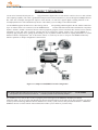


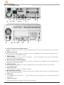
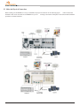

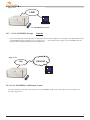


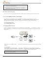
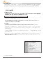
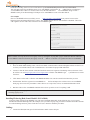
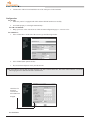
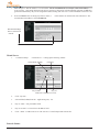
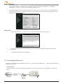

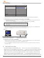
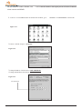


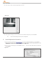
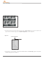
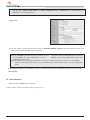

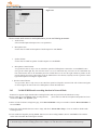
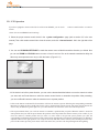
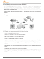
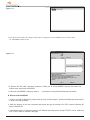

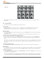
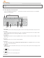


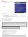
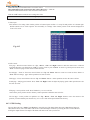
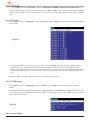
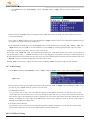
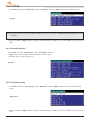
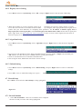

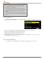
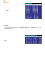
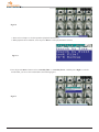


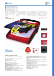


![[U4.12.03] Procédure DEFI_FICHIER](http://vs1.manualzilla.com/store/data/006371253_1-ec3df702d277aa28afdad1e2bb5791e2-150x150.png)