1
International Journal of Emerging Technology and Advanced Engineering
Website: www.ijetae.com (ISSN 2250-2459, ISO 9001:2008 Certified Journal, Volume 3, Issue 5, May 2013)
B. WIRELESS INTERFACING VIA ZIGBEE MODULE
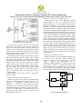
To interface FPGA with robotic applications, wireless
module ZigBee is used. Two modules are used in
experiment. From two, one is Coordinator which works as
transmitter and another is End device which works as
Receiver. Coordinator is attached with PC and End device
is attached with robotic application. Signal is transmitted to
robot from PC through coordinator ZigBee and received by
end device ZigBee. Robot is controlled as per the command
given from PC and logic developed inside the FPGA chip.
Every key pressing of PC represents particular ASCII
values which is transmitted through coordinator ZigBee
and it is wirelessly received end device ZigBee. End device
ZigBee sends the RS232 IC of FPGA board and it sends the
data to the FPGA chip through voltage translator. FPGA
has control logic of PWM signal generation module. So
whenever respectively key is sent through the PC, it will be
received by FPGA chip and will be sent to robot from the
digital I/O port. Any action/movement can be given to
robot by changing just the logic in the FPGA. Using this
concept, any robot can be controlled by FPGA through
wireless module.
Fig. 1. FPGA based wireless control system
For ease of use, the data is sent from PC. For that, Serial
interfacing is done which receives the data serially and
convert it to 8 bit binary numbers. Received 8 bit binary
numbers are stored in 8 bit latch. Here 8 bit latch is used to
store the desired received data for further use. From 8 bit
latched output, all bits are separated to access more number
of ports using less control signal.
From 8 bits of latch, 3 bits go into 3to8 decoder as a data
and 4th bit enables that decoder. Likewise, other 3 bits go
into the other 3to8 decoder as a data and 8th bit enables
that decoder. Output of the decoder is used to enable PWM
module for DC motor and other signals are the input
control signals to drive the DC motor. Other decoder's
output is used to enable the PWM module for Servo motor
and other signals are the input control signals. PWM
modules have separate logic for DC motors and Servo
motors. As per the user input, it can change the values of
respective signals.
Main modules of the control system are described in
next two sections.
C. PWM SIGNAL GENERATION MODULE
PWM is abbreviation of Pulse Width Modulation. It is
also known as the duty-cycle variation method. This
method is commonly used in speed control of motors.
"Pulse” is meant by an electromagnetic wave or
modulation. "Width Modulation” is meant by to adjust to or
keep in proper measure or proportion the width of the
pulse with respect to the frequency of the wave. The duty
cycle is defined as the percentage of digital ‘high’ to digital
‘low’ plus digital ‘high’ pulse-width during a PWM period.
50 MHz
PWM Period
control
20 ns
20 ms
A. SERIAL INTERFACING VIA RS232 PROTOCOL
Whenever any robot is to be remotely controlled through
the PC via wireless module then serial interfacing is very
important to communicate between them. In this
experiment, to control the robot through PC, RS232
interfacing is done. Spartan 3E FPGA kit has on-board
DTE and DCE DB9 port and RS232 voltage translator IC
in the kit. The data signal is transmitted from PC and
received by the FPGA chip using pin 2 and pin 3 of the
DB9 connector respectively.
Input Signal
PWM Duty
cycle Control
Duty Cycle
Up Counter
PWM Reg
PWM Signal
Fig. 2. Block diagram of PWM module
336