1
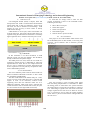
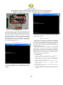
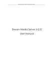
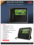
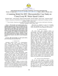
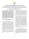
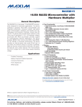
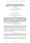
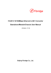
International Journal of Emerging Technology and Advanced Engineering Website: www.ijetae.com (ISSN 2250-2459, Volume 2, Issue 11, November 2012) DEVELOPING OF EMBEDDED GADGET USED TO INTERACT WITH IP-PBX Idrish Shaik1, P V L N Phani2, I Aditya Abhilash3 1, 2 ,3 Department of Electronics and Communication Engineering, Nimra College of Engineering & Technology, Vijayawada Abstract - This project is aimed at implementing IP-PBX based communication system. Today the increased internet has encouraged making the maximum utilization of features provided by the internet. Embedded Ethernet enables us to have a communication system with computers, thus making it easy to use and cost efficient. The data communication over the Ethernet is carried out with a predefined protocol. Usually the protocol used for the communication is TCP-IP protocol. In this project we are using UDP protocol. In this project we intend to build a system where in basic communication within the LAN between devices is possible. This will consist of converting the digital data into a format which can be sent over the Ethernet. Once the communication is established, the data which is to be sent can be decided. Ethernet network supports very high speed communication, thus it is possible to send the status of the analog signal that is connected to the system. In our application we intend to transmit the status of the analog phone over the Ethernet network. Analog Phone line MicroController C D Ethernet (ENC28J60) LAN PC Fig 1: Block diagram of IP-PBX An IP PBX is a combination of a switch/router and a PBX that handles Voice over IP. In an IP PBX, computers can be on a shared LAN that is connected to the IP PBX. Telephones, on the other hand, should be directly connected to the IP PBX. IP PBXs can be used bypass the circuit-switched telephone network by using the data network to connect to branch offices and other locations on the data network. Keywords – EPBX, PSTN, AVRwebserver, IP-PBX, UDP protocol. I. L A/D Converte r INTRODUCTION An IP (Internet Protocol) PBX (Private branch exchange) is a business telephone system designed to deliver voice or video over a data network and interoperate with the normal Public Switched Telephone Network (PSTN). IP PBX server works as proxy server. In IP-PBX there is analog port which is used to connect the local exchange (Phone line). The analog ports convert the signaling information to digital signals that the IP-PBX can process. Telephone calls can also flow through the Ethernet port using IP. The magic of an IP-PBX is that analog and IP calls can be tied together. A PBX is a customer premises telephone system that manages telephones in the enterprise and acts as the gateway to external voice networks. A switch/router directs incoming packets to the appropriate data network. Traditionally, two separate networks are required: one for voice and one for data. Instead of two separate networks, one each for data and voice, only one network is needed if voice is packetized and sent over the data network. II. CONVENTIONAL PBX SYSTEM A PBX system is the user interface system. A PBX acts as gateway to external voice networks. Traditionally, there are two separate networks required. One for voice and one for data. This is called as EPBX system. The usage of two networks can be made into single network by using the IP-PBX concept. In this, IP-PBX instead of two separate networks each one for data and voice, only one network is needed if voice is packetized and sent over the single data network. In an IP-PBX, computers can be on a shared LAN that is connected. Telephones are directly connected to the IPPBX. Using single converged network that carrying both voice and data allows development of new services which are not available on traditional PBX network. 565 International Journal of Emerging Technology and Advanced Engineering Website: www.ijetae.com (ISSN 2250-2459, Volume 2, Issue 11, November 2012) In this, IP addresses are automatically assigned to phones as they connect to system. So a telephone can be moved from one location on the network to another. And while using this system there is no need to change the telephone number that is assigned. III. IV. ENC28J60 ETHERNET CONTROLLER The ENC28J60 is a stand-alone Ethernet controller with an industry standard Serial Peripheral Interface (SPI). It is designed to serve as an Ethernet network interface for any controller equipped with SPI. The ENC28J60 meets all of the IEEE 802.3 specifications. It incorporates a number of packet filtering schemes to limit incoming packets. It also provides an internal DMA module for fast data throughput and hardware assisted checksum calculation, which is used in various network protocols. Communication with the host controller is implemented via an interrupt pin and the SPI, with clock rates of up to 20 MHz two dedicated pins are used for LED link and network activity indication. AVR ATMEGA32 This AVR ATMega32 is the micro-controller that is used for this project. This micro-controller is an 8-bit controller. It has the advanced RISC architecture and 131 powerful instructions. This controller is having 32kbytes of in-system flash memory and 32 general purpose I/O lines along with 4ports. The throughput of this system is 1MIPS per MHZ. In this controller pipelining architecture is available and 32bit instruction set. Fig: 2: Architecture of AVR Fig 3: ENC28J60 Ethernet controller The main function of the CPU core is to ensure correct program execution. The CPU must therefore be able to access memories, perform calculations, control peripherals, and handle interrupts. In order to maximize performance and parallelism, the AVR uses a Harvard architecture–with separate memories and buses for program and data. Instructions in the program memory are executed with a single level pipelining. While one instruction is being executed, the next instruction is pre-fetched from the program memory. This concept enables instructions to be executed in every clock cycle. The program memory is In-System Reprogrammable Flash memory. The fast-access Register File contains 32 × 8-bit general purpose working registers with a single clock cycle access time. This allows single-cycle Arithmetic Logic Unit (ALU) operation. In a typical ALU operation, two operands are output from the Register File, the operation is executed, and the result is stored back in the Register. A. Ethernet Buffer The Ethernet buffer contains transmit and receive memory used by the Ethernet controller. The entire buffer is 8 Kbytes, divided into separate receive and transmit buffer spaces. The sizes and locations of transmit and receive memory are fully programmable by the host controller using the SPI interface. B. Receive Buffer The receive buffer constitutes a circular FIFO buffer managed by hardware. The register pairs ERXSTH: ERXSTL and ERXNDH: ERXNDL serve as Pointers to define the buffer’s size and location within the memory. The ENC28J60 is designed to operate at 25 MHz with a crystal connected to the OSC1 and OSC2 pins. The ENC28J60 design requires the use of a parallel cut crystal. Use of a series cut crystal may give a frequency out of the crystal manufacturer specifications. 566 International Journal of Emerging Technology and Advanced Engineering Website: www.ijetae.com (ISSN 2250-2459, Volume 2, Issue 11, November 2012) V. To send data we simply need to select the data register. Everything is same as the command routine. Following are the steps: UDP P ROTOCOL User Datagram Format (UDP) is simpler, faster and cheaper than TCP. UDP is connectionless and unreliable which means that it does not establish a virtual circuit like TCP, nor does it demand an acknowledge. UDP supports no error recovery or flow control. It merely sends out the message. UDP headers are all 8 bytes, while TCP headers can be 20-60 bytes long. Like TCP, UDP provides delivery of segments using IP. Therefore an UDP-stack is extremely light weight than TCP. UDP uses the same port as TCP. Move data to LCD port. Select data register. Select write operation. Send enable signal. Wait for LCD to process the data. VI. SYSTEM DESIGN This project is one of the modules which will be used for the IP-PBX system. In this module, we are using A/D converter, micro-controller and an Ethernet provider (web server). Fig 4: UDP Header In this checksum is not often calculated, so UDP basically carries only the port numbers. The IP address already contains the total packet length. This UDP protocol is used, where the over head of a connection oriented service is undesirable or where the implementation is small. This is less complex than TCP and it is easy to implement. Typically applications that do not require error recovery but rely on speed use UDP, such as multimedia protocols. V. 2*16 LCD Interface The most commonly used Character based LCDs are based on Hitachi's HD44780 controller or other which are compatible with HD44580. The most LCDs found in the market today are 1 Line, 2 Line or 4 Line LCDs which have only 1 controller and support at most of 80 characters, whereas LCDs supporting more than 80 characters make use of 2 HD44780 controllers. Most LCDs with 1 controller has 14 Pins and LCDs with 2 controller has 16 Pins (two pins are extra in both for back-light LED connections). Fig 6: IP-PBX Module This A/D converter is given an analog input signal from the analog telephone that is connected to it. When the analog phone is connected to the system and when the analog phone is ringing this will produce a voltage of 13V. This voltage is given to the web server board. The voltage required for this web server is about 9V. So this 13V is converted to 9V by using the voltage regulator board which is placed in between the analog board and the web server. Fig 5: LCD pin diagram 567 International Journal of Emerging Technology and Advanced Engineering Website: www.ijetae.com (ISSN 2250-2459, Volume 2, Issue 11, November 2012) Fig 7: AVR Web server This web server is provided with an IP-address and system with other IP-address. These two IP-addresses are made sink with each other. When both these web server and system are made in contact with each other and when the analog phone that is connected is made ring then the LCD that is placed on the micro-controller will display the message that the call is forwarding to the particular system IP-address. And on the PC side it will show the status of the analog phone is in. VII. When the call has been disconnected then the output will be shown as above. VIII. CONCLUSION The goal of the project is to display the message regarding the status of the analog phone on the LCD and PC. This is used to reduce the cost of the equipment and to provide more flexibility for small business firms or companies. These are used to reduce the call charges by using this IP-PBX service. My project is one of the modules of the IP-PBX system. In this project my work is to create the hardware system which is useful for the IP-PBX. The hardware that prepared can be used as one of the module for the hardware PBX system which can be extended in future. Thus the project is successfully done. RESULTS REFERENCES [1 ] LIU, Q. F., ZHOU, H. H., and QIN, Y. J., "Design and Implementation of SIP Phone Based on SCTP and DCCP". [2 ] Design based on the AC494 System on Chip (SoC) family. Audio Codes' AC494.... IP Phones, Gateways and IP-PBX with enhanced data and voice performance. [3 ] Mohsen Gerami. Evaluation of Next Generation Networks. (IJCSE) International Journal on Computer Science and Engineering. [4 ] ETSI standard ES 282 007, V2.0.0, 2008-03; GRLIBIP Library User's Manual, Version 1.0.15. [5 ] J. Rosenberg, Schulzrinne H, Camarillo G, Johnston A, Peterson J, Sparks R, Handley M, and E. Schooler,"SIP: Session Initiation Protocol. The above dialog box gives the output status when ringing is taken place at the IP address that we have assigned. 568