1
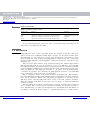
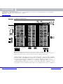
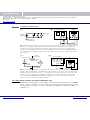
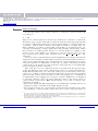
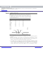
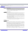
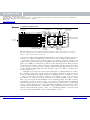
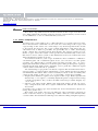
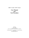
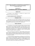
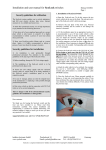
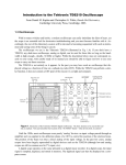
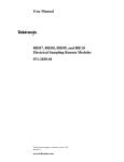
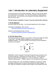
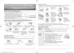
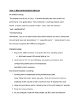
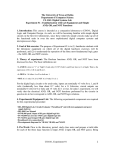
Cambridge University Press
0521815363 - Hands-On Electronics: A One-Semester Course for Class Instruction or Self-Study
Daniel M. Kaplan and Christopher G. White
Excerpt
More information
1
Equipment familiarization: multimeter,
breadboard, and oscilloscope
In this chapter you will become acquainted with the ‘workhorses’ of electronics testing and prototyping: multimeters, breadboards, and oscilloscopes. You will find these to be indispensable aids both in learning about
and in doing electronics.
Apparatus required
One dual-trace oscilloscope, one powered breadboard, one digital multimeter, two 10X attenuating scope probes, red and black banana leads, two
alligator clips.
1.1 Multimeter
You are probably already familiar with multimeters. They allow measurement of voltage, current, and resistance. Just as with wristwatches and
clocks, in recent years digital meters (commonly abbreviated to DMM for
digital multimeter or DVM for digital voltmeter) have superseded the analog meters that were used for the first century and a half or so of electrical
work. The multimeters we use have various input jacks that accept ‘banana’
plugs, and you can connect the meter to the circuit under test using two
banana-plug leads. The input jacks are described in Table 1.1. Depending
on how you configure the meter and its leads, it displays
r the voltage difference between the two leads,
r the current flowing through the meter from one lead to the other, or
r the resistance connected between the leads.
Multimeters usually have a selector knob that allows you to select what is
to be measured and to set the full-scale range of the display to handle inputs
of various size. Note: to obtain the highest measurement precision, set the
knob to the lowest setting for which the input does not cause overflow.
1
© Cambridge University Press
www.cambridge.org
Cambridge University Press
0521815363 - Hands-On Electronics: A One-Semester Course for Class Instruction or Self-Study
Daniel M. Kaplan and Christopher G. White
Excerpt
More information
2
Hands-on electronics
Table 1.1. Digital multimeter inputs.
Input jack
Purpose
Limitsa
COM
V
mA
10 A
reference point used for all measurements
input for voltage or resistance measurements
input for current measurements (low scale)
input for current measurements (high scale)
1000 V DC/750 V AC
200 mA
10 A
a
For the BK Model 2703B multimeters used in the authors’ labs.
To avoid damaging the meter, be sure to read the safety warnings in its
data sheet or instruction booklet.
1.2 Breadboard
‘Breadboard’ may seem a peculiar term! Its origins go back to the days
when electronics hobbyists built their circuits on wooden boards. The
breadboards we use represent a great step forward in convenience, since
they include not only sockets for plugging in components and connecting
them together, but also power supplies, a function generator, switches, logic
displays, etc.
The exercises that follow were designed using the Global Specialties
PB-503 Protoboard. If you do not have access to a PB-503, any suitable
breadboard will do, provided you have a function generator and two variable
power supplies. Additional components that you will need along the way
(that are built into the PB-503) include a 1 k and a 10 k potentiometer,
a small 8 speaker, two debounced push-button switches, several LED
logic indicators, and several on–off switches.
Fig. 1.1 displays many of the basic features of the PB-503. (For simplicity, some PB-503 features that will be used in experiments in later chapters
have been omitted.) While the following description is specific to the
PB-503, many other breadboards share some, if not all, of these features.
The description will thus be of some use for users of other breadboard
models as well.
The breadboard’s sockets contain spring contacts: if a bare wire is pushed
into a socket, the contacts press against it, making an electrical connection. The PB-503’s sockets are designed for a maximum wire thickness of
22 AWG (‘American Wire Gauge’) – anything thicker (i.e., with smaller
© Cambridge University Press
www.cambridge.org
Cambridge University Press
0521815363 - Hands-On Electronics: A One-Semester Course for Class Instruction or Self-Study
Daniel M. Kaplan and Christopher G. White
Excerpt
More information
3
1 Equipment familiarization
+15
−15
+5 V
+15 V
−15 V
Voltage Adjustment Knobs
Horizontal Row
(Group of 5)
Amplitude
Slider
Frequency
Slider
Function
Generator
Analog
Digital
8Ω
Speaker
Push Button
De-Bounced
Switches
Vertical Column
(Group of 25)
10 k pot
Logic Switch Bank
1 k pot
SPDT Switches
Fig. 1.1. Illustration showing many of the basic features of the PB-503 powered
Protoboard, with internal connections shown for clarity. Note that each vertical column is
broken into halves with no built-in connection between the top and bottom.
AWG number) may damage the socket so that it no longer works reliably
for thin wires. The PB-503 sockets are internally connected in groups of
five (horizontal rows) or twenty five (vertical columns; see Fig. 1.1).
Each power supply connects to a ‘banana’ jack and also to a row of
sockets running along the top edge of the unit. The three supplies, +5 V
(red jack), +15 V (yellow jack), and −15 V (blue jack), have a common
© Cambridge University Press
www.cambridge.org
Cambridge University Press
0521815363 - Hands-On Electronics: A One-Semester Course for Class Instruction or Self-Study
Daniel M. Kaplan and Christopher G. White
Excerpt
More information
4
Hands-on electronics
‘ground’ connection (black jack). The +15 V and −15 V supplies are
actually adjustable, using the knobs provided, from less than 5 volts to
greater than 15 volts.
1.2.1 Measuring voltage
Voltage is always referenced to something, usually a local ground. For the
following exercises you will measure voltage with respect to the breadboard
ground, which is also the common ground for the three power supplies. To
measure a voltage, you will first connect the ‘common’ jack of the meter to
the breadboard common (i.e., breadboard ground). Next you will connect
the meter’s ‘voltage’ jack to the point of interest. The meter will then tell
you the voltage with respect to ground at this one point.
When connecting things, it’s always a good idea to use color coding to
help keep track of which lead is connected to what. Use a black bananaplug lead to connect the ‘common’ input of the meter to the ‘ground’ jack
of the breadboard (black banana jack labeled with a ‘ ’ or ‘ ’ symbol).
Use a red banana-plug lead with the ‘V’ input of the meter.
Since the DMM is battery powered, it is said to ‘float’ with respect to
ground (i.e., within reason,1 one may connect the DMM’s common jack to
any arbitrary voltage with respect to the breadboard ground). It is therefore
possible to measure the voltage drop across any circuit element by simply
connecting the DMM directly across that element (see Fig. 1.2).
Warning: This is not true for most AC-powered meters and oscilloscopes.
To practice measuring voltages, measure and record the voltage between
each power supply jack and ground. In each case set the meter’s range
for the highest precision (i.e., one setting above overflow).
Adjust the +15 V and −15 V supplies over their full range and record
the minimum and maximum voltage for each. Carefully set the +15 V
supply to a voltage half-way between its minimum and maximum for
use in the next part.
1
If you wonder what we mean by ‘within reason’, ask yourself what bad thing would happen if
you connected the DMM common to, say, twenty million volts – if you’re interested, see e.g.
H. C. Ohanian, Physics, 2nd edition, vol. 2, ‘Interlude VI’ (Norton, New York, 1988), esp.
pp. VI–8 for more information on this.
© Cambridge University Press
www.cambridge.org
Cambridge University Press
0521815363 - Hands-On Electronics: A One-Semester Course for Class Instruction or Self-Study
Daniel M. Kaplan and Christopher G. White
Excerpt
More information
5
1 Equipment familiarization
(a)
(b)
Power Supply
DMM
Multimeter
+
Power
Supply
V
+
Ground
(Common)
_
A
mA COM VΩ
1 µF
Fig. 1.2. Measuring voltage. (a) An arbitrary circuit diagram is shown as an illustration of
how to use a voltmeter. Note that the meter measures the voltage drop across both the
resistor and capacitor (which have identical voltage drops since they are connected in
parallel). (b) A drawing of the same circuit showing how the leads for a DMM should be
connected when measuring voltage. Notice how the meter is connected in parallel with
the resistor.
(a)
Potentiometer
Slider
(Center Tap)
(b)
Power Supply
DMM
+
0.011 A
Multimeter
A
+
Power
Supply
_
A
mA COM VΩ
Ground
(Common)
Fig. 1.3. Measuring current. (a) Schematic diagram of series circuit consisting of power
supply, 10 k potentiometer, and multimeter. (Note that the center tap of the potentiometer
is left unconnected in this exercise – accidentally connecting it to power or ground could
lead to excessive current flow and burn out the pot.) (b) A drawing of the same circuit
showing how the DMM leads should be configured to measure current. Note that the
meter is connected in series with the resistor.
1.2.2 Measuring current; resistance and Ohm’s law
Current is measured by connecting a current meter (an ammeter, or a DMM
in its ‘current’ mode) in series with the circuit element through which the
current flows (see Fig. 1.3). Note carefully the differences between Fig. 1.2
and Fig. 1.3.
© Cambridge University Press
www.cambridge.org
Cambridge University Press
0521815363 - Hands-On Electronics: A One-Semester Course for Class Instruction or Self-Study
Daniel M. Kaplan and Christopher G. White
Excerpt
More information
6
Hands-on electronics
Recall that Ohm’s law relates current I , voltage V , and resistance R
according to
V = IR.
(1.1)
This is not a universal law of electrical conduction so much as a statement
that there exist certain materials for which current is linearly proportional
to voltage.2 Materials with such a linear relationship are used to fabricate
‘resistors’: objects with a known and stable resistance. Usually they are
little cylinders of carbon, carbon film, metal film, or wound-up wire, encased in an insulating coating, with wire leads sticking out the ends. Often
the resistance is indicated by means of colored stripes according to the
resistor color code (Table 1.2). Resistors come in various sizes according to their power rating. The common sizes are 18 W, 14 W, 12 W, 1 W,
and 2 W.
You can easily verify this linear relationship between voltage and current
using the fixed 10 k (10 000 ohm) resistance provided between the two
ends of one of the breadboard’s ‘potentiometers’. A potentiometer is a type
of resistor that has an adjustable ‘center tap’ or ‘slider’, allowing electrical
connections to be made not only at the two ends, but also at an adjustable
point along the resistive material.
The ‘10 k pot’ (as it is called for short) is located near the bottom edge
of the breadboard, and can be adjusted by means of a large black knob.3
Inside the breadboard’s case, the ends of the pot (as well as the center tap)
connect to sockets as labeled on the breadboard’s front panel. By pushing
wires into the sockets you can make a series circuit (Fig. 1.3) consisting of
an adjustable power supply, the 10 k pot, and the multimeter (configured
to measure current). You can attach alligator clips to the meter leads to
connect them to the wires. But, before doing so, be sure to observe the
following warnings:
r First, turn off the breadboard power to avoid burning anything out if you
happen to make a mistake in hooking up the circuit.
r Be careful to keep any exposed bits of metal from touching each other
and making a ‘short circuit’! Note that most of the exposed metal on
2
3
Of course, the existence of other materials (namely semiconductors) for which the I –V relationship
is nonlinear makes electronics much more interesting and underlies the transformation of daily life
brought about by electronics during the twentieth century.
If you don’t have a PB-503 breadboard, find a 10 k pot on your breadboard if it has one; otherwise
you will have to purchase a separate 10 k pot.
© Cambridge University Press
www.cambridge.org
Cambridge University Press
0521815363 - Hands-On Electronics: A One-Semester Course for Class Instruction or Self-Study
Daniel M. Kaplan and Christopher G. White
Excerpt
More information
7
1 Equipment familiarization
Table 1.2. Color code for nonprecision resistors (5, 10, or 20% tolerance).
The resistance in ohms is the sum of the values in columns 1 and
2, multiplied by the value in column 3, plus or minus the tolerance
in column 4. For example, the color code for a 1 k resistor would
be ‘brown--black--red’, for 51 ‘green--brown--black’, for 330 ‘orange--orange--brown’, etc.
Stripe:
1
2
3
Black
Brown
Red
Orange
Yellow
Green
Blue
Violet
Gray
White
0
10
20
30
40
50
60
70
80
90
0
1
2
3
4
5
6
7
8
9
100
101
102
103
104
105
106
107
108
109
Gold
Silver
None
4 (tolerance)
5%
10%
20%
Stripe 2
Stripe 1
Stripe 3
Tolerance Stripe
the breadboard (screw heads for example) has a low-resistance path to
ground.
r If you accidentally connect power or ground to the potentiometer’s center
tap, you can easily burn out the pot, rendering it useless! If in doubt, have
someone check your circuit before turning on the power.
Use Ohm’s law to predict the current that will flow around the circuit
if you use the power supply that you set to its midpoint in the previous
exercise. What current should flow if the supply is set to its minimum
voltage? What is the current if the supply is set to its maximum voltage?
© Cambridge University Press
www.cambridge.org
Cambridge University Press
0521815363 - Hands-On Electronics: A One-Semester Course for Class Instruction or Self-Study
Daniel M. Kaplan and Christopher G. White
Excerpt
More information
8
Hands-on electronics
Now turn on the breadboard power, measure the currents for these three
voltages, and compare with your predictions. Make a graph of voltage vs.
current from these measurements. Is the relationship linear? How close
is the slope of voltage vs. current to 10 k?
1.2.3 Measuring resistance
Now turn off the breadboard power and disconnect your series circuit. In
this and the following part, the pot should connect only to the meter.
Set the meter for resistance and measure and record the resistance
between the two ends of your 10 k pot. Due to manufacturing tolerances,
you will probably find that it is not exactly 10 k. By what percentage
does it differ from the nominal 10 k value? Does the measured value
agree more closely with the slope you previously measured than with
the nominal value? Explain.
Now connect the meter between the center tap and one end of the pot.
What resistance do you observe? What happens to the resistance as you
turn the potentiometer’s knob?
Leaving the knob in one place, measure and record the resistance between
the center tap and each end. Do the two measurements add up to the total
you measured above? They should – explain why.
1.3 Oscilloscope
With its many switches and knobs, a modern oscilloscope can easily intimidate the faint of heart, yet the scope is an essential tool for electronics
troubleshooting and you must become familiar with it. Accordingly, the
rest of this laboratory session will be devoted to becoming acquainted with
such an instrument and seeing some of the things it can do.
The oscilloscope we use is the Tektronix TDS210 (illustrated in Fig. 1.4).
If you don’t have a TDS210, any dual-trace oscilloscope, analog or digital,
can be used for these labs as long as the bandwidth is high enough – ideally,
30 MHz or higher. While the description below may not correspond exactly
to your scope, with careful study of its manual you should be able to figure
out how to use your scope to carry out these exercises.
The TDS210 is not entirely as it appears. In the past you may have
used an oscilloscope that displayed voltage as a function of time on a
© Cambridge University Press
www.cambridge.org
Cambridge University Press
0521815363 - Hands-On Electronics: A One-Semester Course for Class Instruction or Self-Study
Daniel M. Kaplan and Christopher G. White
Excerpt
More information
9
1 Equipment familiarization
Seconds per
Division
AUTOSET
MEASURE
CURSOR
HORIZONTAL
CONTROLS
60 MHz
1 GS/s
TDS 210
Trigger Info
MENU
Menu
Options
TRIGGER LEVEL
Menu
Options
TRIGGER MENU
Menu
Options
Menu
Options
Volts per
Division
Menu
Options
Horizontal and Vertical Info
Trigger Level
CH 1
CALIBRATION
CONTACT POINT
MENU
OPTION
BUTTONS
CH 2
VOLTS/DIV
SEC/DIV
VERTICAL
CONTROLS
Fig. 1.4. Illustration of the Tektronix TDS210 digital oscilloscope. The basic features to
be used in this tutorial are marked. Note and remember the location of the ‘autoset’
button – when all else fails, try autoset!
cathode-ray tube (CRT). While the TDS210 can perform a similar function,
it does not contain a CRT (part of the reason it is so light and compact).
Until the 1990s, most oscilloscopes were purely ‘analog’ devices: an
input voltage passed through an amplifier and was applied to the deflection
plates of a CRT to control the position of the electron beam. The position
of the beam was thus a direct analog of the input voltage. In the past few
years, analog scopes have been largely superseded by digital devices such
as the TDS210 (although low-end analog scopes are still in common use
for TV repair, etc.).
A digital scope operates on the same principle as a digital music recorder.
In a digital scope, the input signal is sampled, digitized, and stored in
memory. The digitized signal can then be displayed on a computer screen.
One of your first objectives will be to set up the scope to do some of
the things for which you may already have used simpler scopes. After
that, you can learn about multiple traces and triggering. In order to have
something to look at on the scope, you can use your breadboard’s built-in
function generator, a device capable of producing square waves, sinusoidal
waves, and triangular waves of adjustable amplitude and frequency. But
start by using the built-in ‘calibrator’ signal provided by the scope on a
metal contact labeled ‘probe comp’ (or something similar), often located
near the lower right-hand corner of the display screen.
© Cambridge University Press
www.cambridge.org
Cambridge University Press
0521815363 - Hands-On Electronics: A One-Semester Course for Class Instruction or Self-Study
Daniel M. Kaplan and Christopher G. White
Excerpt
More information
10
Hands-on electronics
Note that a leg folds down from the bottom of the scope near the front
face. This adjusts the viewing angle for greater comfort when you are seated
at a workbench, so we recommend that you use it.
1.3.1 Probes and probe test
Oscilloscopes come with probes: cables that have a coaxial connector (similar to that used for cable TV) on one end, for connecting to the scope, and
a special tip on the other, for connecting to any desired point in the circuit
to be tested. To increase the scope’s input impedance and affect the circuit under test as little as possible, we generally use a ‘10X’ attenuating
probe, which has circuitry inside that divides the signal voltage by ten.
Some scopes sense the nature of the probe and automatically correct for
this factor of ten; others (such as the TDS210) need to be told by the user
what attenuation setting is in use.
As mentioned above, your scope should also have a built-in ‘calibrator’
circuit that puts out a standard square wave you can use to test the probe
(see Fig. 1.4). The probe’s coaxial connector slips over the ‘ch 1 ’ or ‘ch 2 ’
input jack and turns clockwise to lock into place. The probe tip has a springloaded sheath that slides back, allowing you to grab the calibrator-signal
contact with a metal hook or ‘grabber’.
An attenuating scope probe can distort a signal. The manufacturer therefore provides a ‘compensation adjustment’ screw, which needs to be tuned
for minimum distortion. The screw is usually located on the assembly that
connects the probe to the scope, or, occasionally, on the tip assembly.
Display the calibrator square-wave signal on the scope. If the signal looks
distorted (i.e., not square), carefully adjust the probe compensation using
a small screwdriver. (If you have trouble achieving a stable display, try
‘autoset’.)
Check your other probe. Make sure that both probes work, are properly compensated, and have equal calibrations. Sketch the observed
waveform.
(Consult your oscilloscope user manual for more information about carrying out a probe test.)
Note that each probe also has an alligator clip (sometimes referred to
as the ‘reference lead’ or ‘ground clip’). This connects to the shield of the
coaxial cable. It is useful for reducing noise when looking at high-frequency
© Cambridge University Press
www.cambridge.org