1
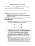
The University of Texas at Dallas
Department of Computer Science
CS 4141: Digital Systems Lab
Experiment #1 – Familiarization with Lab Equipment and Simple
AND, OR, and NOT Functions
1. Introduction: This course is intended as a companion laboratory to CS4341, Digital
Logic and Computer Design. As such, we will be becoming familiar with simple digital
circuits in the first few laboratories, since these relatively simple circuits make up all of
the functional units in even the most sophisticated digital computer systems and
microprocessor chips.
2. Goal of this exercise: The purpose of Experiment #1 is to (1) familiarize students with
the laboratory equipment on which all of the digital hardware exercises will be
performed, and (2) to understand the operation of the three most fundamental logic gates
– the AND, OR, and NOT circuits.
3. Theory of experiment: The Boolean functions AND, OR, and NOT have been
discussed in class. The basic definitions are:
• A AND B is true (or “1” or “high”) if and only if (“iff”) both A and B are true (or 1 or high). That is, the
expression A·B is 1 iff A and B are 1.
• A OR B is 1 if either A or B or both are 1.
• NOT A is 1 only if A is 0; NOT A is 0 only if A is 1.
For the digital logic circuits to be used today, inputs are nominally +5 volts for a 1, and 0
volts (technically less than about 0.7 volts) for a 0. Likewise, circuit outputs are
nominally 0 volts for 0 or false and +5 volts for 1 or true. In today’s experiment, we will
verify that the electrical AND, OR, and NOT functions performed by the circuits in
question do in fact correspond to AND, OR, and NOT logic relations.
4. Experimental Equipment List: The following experimental components are required
for this experimental procedure:
• IDL-800 Digital Lab. Circuits Evaluator (“breadboard” unit with test equipment and power
supply built in)
• IDL-800 User Manual
• SN74LS08 quad 2-input AND gate (digital logic kit)
• SN 74LS04 hex inverter (NOT) gate (digital logic kit)
• SN 74LS32 quad 2-input OR gate (digital logic kit)
• Breadboard wire connection kit
• Pin assignment diagrams for 74LS04, 74LS08, and 74LS32
5. Pre-Work: Prior to the laboratory period, study class notes and prepare a truth table
for each of the three logic function (2-input AND, 2-input OR, and NOT gates). Bring
CS4141, Experiment #1
2
these truth tables to the laboratory. Also prepare truth tables for the two functions defined
in part 9 of Section 6 below and bring them to the lab.
6. Experimental Procedure:
Equipment Familiarization
1) Become familiar with the IDL-800 chassis (refer to the manual at any time if additional clarification is
needed). Note that the rear panel (forward-facing near-vertical panel at the back of unit) contains the master
power on-off switch. In addition, the left side of the panel contains a function generator which can generate
an electrical signal in three forms: sinusoidal, triangular, and square wave. Both the frequency and
amplitude can be varied. On the right side of the panel, there is a digital voltmeter that can measure various
voltages applied to circuits. Note that the voltmeter can be connected either to banana plugs or the small
wire connectors that are used to connect circuit pins together.
2) Study the flat portion of the IDL-800 chassis. On the left side are two +5VDC (non-variable) power
outputs, plus a variable DC supply with outputs of 0-15 and 0-(-15) V. On the right are wire connector-tobanana plug adapters and other inputs (which will not be used in this lab). At the bottom are some function
switches that can apply +/− 5V, and two “pulse” switches which will apply a 1 (5V) or 0 (0V) as long as
they are held down. There are also 8 “data” switches that can be switched to apply 1 or 0 (5V or 0V) to any
input. At the rear of the flat board are data indicators, including two seven segment displays which will
display numbers, and 8 light-emitting diode (LED) indicators which can be connected to circuit pins to
indicate whether a one (5V) or a 0 (0V) is present. A 1 will light up the LED; a 0 turns it off.
3) The center of the flat chassis area is the prototype board. At the top and bottom are “power busses.”
When these are connected by the small solid copper wires to one of the supplies (red to +, blue to ground or
0), all the other holes in the respective lines connect to that voltage element.
4) Note that the prototype board contains two main areas of pins. When a chip is plugged into any set of
pins in such a way that it bridges the wide space in the middle of each pin group, all pin holes in each
vertical column which contains a chip pin are also connected to that pin. Thus other components, inputs, or
voltages can be connected to each pin of the circuit being evaluated.
5) Take some time to study the chassis, and ask questions of the instructor or TA if necessary.
Experimental Procedure
6) NOT Function:
• Find the hex inverter (74LS04) and carefully plug it into the breadboard in either the upper or lower
section. Make sure that the long dimension of the chip package points left-right, with the notch on the left,
and that the chip “legs” bridge the wide space in the middle of the hole array. The exact location of the chip
from left to right on the board is arbitrary.
• Make sure the master power is off. Using the small solid copper wires from the kit supplied, connect +5V
to pin 14 and 0V (ground) to pin 7. Remember that the “notch” is located on the end of the chip where pin
1 is. Looking down from the top, pin 1 is on the left, and pin 14 is on the right; pin numbering is counterclockwise from 1 to 14 (refer to diagram on last page).
• There are six inverters (NOT functions) on the chip. Any will do equally well, but this example uses the
first, which has input on pin 1 and output on pin 2. Connect one of the data switch outputs at the bottom of
the panel (bottom right) to the input (pin 1) of the inverter. Connect the output of the inverter (pin 2) to one
of the LED diode inputs at the top of the horizontal portion of the IDL-800. Make sure that the data switch
is in the 0 position.
CS4141, Experiment #1
3
• Turn on the power. Verify that the LED is on; since the input is 0, the output should be 1 (0V), so the
diode should be illuminated.
• Turn the data switch to 1. Verify that the LED is extinguished. The input is now 1, so the output is NOT1, or 0. Toggle the switch several times to verify that the inverter or NOT gate output is always opposite of
the input.
• Turn off the power and disconnect the circuit connections.
7) AND Function:
• Find the 74LS08 chip and plug it into the board as you did the 74LS04. Connect pins 7 and 14 to ground
and +5V as before. Note that there are 4 equal AND circuits on the chip, but these instructions use the first
one numerically (refer to the pin-out diagram as needed).
• Connect two data switches to the AND gate inputs, pins 1 and 2. Make sure both inputs are 0. Connect the
AND gate output, pin 3, to an LED input.
• Turn on the power. Verify that the LED is off. Turn one data switch on (to 1). The LED should stay off.
Turn that data switch back to 0, and turn the other to 1. The LED should still be off. Now turn both
switches on (to 1). The LED should light. This verifies that the AND function is as defined – the output is 1
iff both inputs are 1. Try this switching several times to get the “feel” of the circuit.
• Turn off the power and disconnect the circuit connections.
8) OR Function:
• Find the 74LS32 chip and plug it into the board as you did the other circuits. Connect pins 7 and 14 to
ground and +5V, respectively, as before. Note that there are 4 equal OR circuits on the chip, but these
instructions use the first one numerically (refer to the pin-out diagram as needed).
• Connect two data switches to the OR gate inputs, pins 1 and 2. Make sure both inputs are 0. Connect the
OR gate output, pin 3, to an LED input.
• Turn on the power. Verify that the LED is off. Turn one data switch on (to 1). The LED should light up.
Turn that data switch back to 0, and turn the other to 1. The LED should light up once again. Now turn both
switches on (to 1). The LED should light under this condition also. This verifies that the OR function is as
defined – the output is 1 if either or both inputs are 1. Try this switching several times as above to get the
“feel” of the circuit.
• Turn off the power and disconnect the circuit connections.
9) Solving for several expressions:
• Consider the following expression: Y=(A•B) • (C•D). Use the quad AND gate chip to connect a circuit
which will satisfy this expression (you should have the truth table done as part of the pre-work). Verify that
Y is 1 iff A-D are 1.
_____
_____
• Construct a circuit for the following Boolean relation: Y = (A • B) + (C • D) Remember that we use a
line over the expression to mean “NOT.” Verify with your truth table that the circuit is working correctly.
7. Equipment Disassembly: The experimental procedure is complete. Please
disassemble the circuit wiring, replace in the wiring kit box and replace it as you found it
CS4141, Experiment #1
4
in the cabinet. Turn in the logic circuit kit to the instructor or the TA. Make sure that your
work area is clean.
8. Laboratory Report: Your laboratory report should follow the form given. In your
write-up, discuss the operation of the circuits and the verification of the function of each.
Also do the following:
• Show the circuit hook-up for each of the circuits that you connected. Make sure you remember to
show the pin numbers of the gates that you connected.
• Prepare circuit diagrams for the two Boolean expressions in the last part of your exercise above.
Show these in your report.
• A NAND gate is a gate such that the output is 0 iff both inputs are 1; otherwise, the output is 0. How
would you construct a NAND function from the circuits given? Show the diagram.
• Similarly, a NOR gate is constructed such that the output is 0 if either or both inputs are 1; it is one
only if both inputs are 0. Show a diagram for this circuit from the given components.
Acknowledgment: Prof. Herman Harrison
CS4141, Experiment #1
5