1
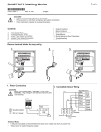
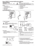
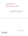
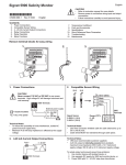
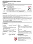
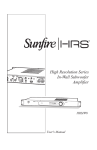
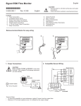
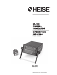
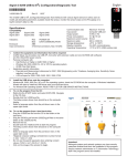
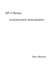
English
8860 Dual Channel Conductivity/Resistivity Controller
*3-8860.090*
3-8860.090 Rev. E 3/06 English
C1
C2
CAUTION!
•
•
•
Remove power to unit before wiring input and output connections.
Follow instructions carefully to avoid personal injury.
This product should only be used for the purposes and in the manner described in this manual.
Relay 1
23.45 µS
8.72 µS
Signet
Conductivity/Resistivity
Transmitter
Relay 2
ENTER
Installation
1.
2.
3.
4.
5.
Punch out panel and de-burr edges. Recommended clearance on all sides between instruments is 1 inch.
Place gasket on instrument, and install in panel.
Slide mounting bracket over back of instrument until quick-clips snap into latches on side of instrument.
Connect wires to terminals.
To remove, secure instrument temporarily with tape from front or grip from rear of instrument. DO NOT RELEASE. Press
quick-clips outward and remove.
6. If cleaning is necessary, wipe the front of the unit with a damp cloth.
7. The live contacts on the back of this unit must be covered to avoid accidental shock hazard.
gasket on
front side
of panel
96mm (3.8 in.)
panel
terminals
Panel Cutout
REL
N/C
N/C
N/C
56 mm
(2.2 in.)
Specifications
General
Compatible electrodes:
N/O
N/O
N/O
COM
POW
ER
COM
L
COM
N
COM
SGNL 2
TEMP 2
ISO GND
SHLD
SGNL 1
TEMP 1
ISO GND
OPEN
COLL 3,4
-
- OPEN COLL 4
OPEN COLL 3
N/O
N/C
OUTPUT OPTION
3.6 x 3.6 in.
(+0.031, -0 in.)
102 mm
(4.0 in.)
mounting
bracket
AY 4
REL
AY 3
REL
AY 2
REL
AY 1
SHLD
Optional
Rear Cover
92 x 92 mm
(+ 0.8, - 0 mm)
RELAY 3,4
96 mm
(3.8 in.)
quick-clip
•
Signet 2819 to 2823
Standard or Certified
Conductivity/Resistivity Sensors
Enclosure:
• Rating: NEMA 4X/IP65 front (NEMA 4X Rear cover available)
• Case: PBT
• Panel case gasket: Neoprene
• Window: Polyurethane-coated polycarbonate
• Keypad: Sealed 4-key silicone rubber
• Weight: 8860-AC: 1.28 lb/0.58 kg 8860: 1.2 lb/0.55 kg
Display (Alphanumeric 2 x 16 LCD) :
• Contrast: User selected, 5 levels
• Update rate: 1.5 seconds
Sensor input range:
• Conductivity: 0.01 µS/cm to 400 000 µS/cm
• Resistivity:
10 KΩ•cm to 100 MΩ•cm
• TDS: 0.023 to 200 000 PPM nominal (adjustable µS/PPM)
• Temperature:
-25 to 120°C (-13 to 248°F) PT 1000; 25ºC = 1096Ω
Accuracy:
• Conductivity/Resistivity: ± 2% of reading
• Temperature:
± 0.5ºC (0 to 100ºC)
Electrical
Power requirements:
3-8860-AC: 100 to 240 VAC ± 10% , 50-60 Hz, 20VA or
11 to 24 VDC ±10%, regulated, 0.5 A max
3-8860:
11 to 24 VDC ±10%, regulated, 0.5 A max
Three 4 to 20 mA Outputs:
• Passive, isolated, fully adjustable and reversible
4 to 20 mA outputs are independently source selectable
Max loop impedance:
150 Ω @ 12 V, 450 Ω @ 18 V, 750 Ω @ 24 V
• Update rate: ~100 mS
• Accuracy: ±0.03 mA @ 25°C, 24 VDC
Open-collector outputs (2 available, optically isolated):
• 50 mA sink or source, 30 VDC max. pull-up voltage
• Programmable for:
• High or Low setpoint with adjustable hysteresis
• Pulse operation (max. rate: 400 pulses/min)
• USP standards
• Time delay: 0 to 6400 s.
Relay outputs (up to 4 SPDT relays available )
• Maximum resistive load: 5 A @ 250 VAC, 5 A @ 30 VDC
• Isolation between open contacts: 500 V minimum
• Programmable for:
• High or Low setpoint with adjustable hysteresis
• Pulse operation (max. rate: 400 pulses/min)
• USP standards
• Time delay: 0 to 6400 s
Environmental
• Ambient operating temperature:
• Storage temperature:
• Relative humidity:
• Maximum altitude:
• Insulation category:
• Pollution degree:
-10 to 55°C (14 to 131°F)
-15 to 80°C (5 to 176°F)
0 to 95%, non-condensing
2000 m (6562 ft)
II
2
Standards and Approvals
• CE, UL listed
• Immunity:
EN50082-2
• Emissions:
EN55011 Class B
• Manufactured under ISO 9001, ISO 14001
Electrical Connections
Caution: Failure to fully open terminal jaws before removing wire may permanently damage instrument.
This product must be provided with a means to disconnect all current carrying conductors connected to the main AC line, or,
as part of the building installation.
Wiring Procedure
1. Remove 0.35- 0.47 in. (9-12 mm) of insulation from wire end.
2. Press the orange terminal lever downward with a small screwdriver to open terminal jaws.
3. Insert exposed (non-insulated) wire end in terminal hole until it bottoms out.
4. Release orange terminal lever to secure wire in place. Gently pull on each wire to ensure a good connection.
Wiring Removal Procedure
1. Press the orange terminal lever downward with a small screwdriver to open terminal jaws.
Wiring Tips:
• Do not route sensor cable in conduit containing AC power wiring - electrical noise may interfere
with sensor signal.
• Routing sensor cabling in grounded metal conduit may prevent moisture damage, electrical
noise, and mechanical damage.
• Seal cable entry points to prevent moisture damage.
Caution:
• Do not insert two wires into a single terminal. If necessary, splice the wires together before
Electrical shock hazard exists!
inserting into the terminal.
♦
Never connect live AC lines to the
instrument.
♦
N/C N/O COM
*
N/C N/O COM
LOOP 3
+
SGNL 2
L
N
N
-
-
+
+
•
LR92369
4 to 20 mA loop Outputs
The current loops in the 8860 are passive circuits.
12-24 VDC must be provided from an external source.
A single loop is illustrated for clarity.
In OPEN COLLECTOR position, relays 3 and 4 are open
collector outputs as shown.
In RELAY 3, 4 position, relays 3 and 4 are dry contact relays
identical to relays 1 and 2.
The menu references in the 8860 display will not change.
Outputs 3 and 4 will be identified as "Relay" regardless of
switch setting.
Internal open-collector
output circuit
8860 4 to 20 mA outputs
- +
- + - +
PLC or Recorder
Outputs
-
+
+
2
3-8860.610A 4/00
Loop 1
•
11 - 24V
0.5 A
LISTED
E171559
Output Option Switch
•
~
100 - 240V
50-60Hz, 20VA
Loop 3
LOOP 3
TEMP 2
SHLD
ISO GND
SGNL 1
L
Loop 2
LOOP 2
LOOP 2
LOOP 1
+
-
LOOP 1
TEMP 1
ISO GND
SHLD
OPEN
COLL 3,4
Always connect a ground wire to
the ground terminal when using
AC power.
RELAY 4
POWER
+ OPEN COLL 3
OPEN COLL 3
-
N/C N/O COM
RELAY 3
ÜL
RELAY 3,4
OUTPUT OPTION
- OPEN COLL 4
+ OPEN COLL 4
N/C N/O COM
RELAY 2
+
RELAY 1
Channel 1
4-20 mA in
Channel 2
4-20 mA in
Channel 3
4-20 mA in
+
+
+
-
+
-
Power
Supply
12-24 VDC
8860 Dual Channel Conductivity/Resistivity Controller
Sensor Input Connections
3-2822, 3-2842
3-2819, 3-2839
(1.0 Cell)
( 0.10 Cell)
(0.01 Cell)
100mS 200mS 1,000mS
10KΩ
RED
WHITE
BLACK
SILVER (SHLD)
400,000mS
10,000mS
100,000mS
50,000mS
200,000mS
SGNL 2
10mS
100KΩ
TEMP 2
1mS
1MΩ
ISO GND
0.054mS
18.3 MΩ
(20.0 Cell)
(10.0 Cell)
3-2821, 3-2841
3-2820, 3-2840
0.010mS
100 MΩ
Deionization Regen. Chemicals
Alkali Cleaners, Acids/Bases
Brackish Sea Water
(Salinity)
3-2823
Rinse
Water
SHLD
SHLD
•
Cooling Tower
Waste Waters
Bottled
Water
UPW @ 25°C USP
SGNL 1
•
•
TEMP 1
•
The 8860 will accept two independent sensor input signals.
The two sensors may be of different cell constant values.
Do not route sensor cable in any conduit containing AC power
wiring - electrical noise may interfere with the signal.
Cable shield MUST be maintained through cable splice.
Use three conductor shielded cable for cable extensions up
to 30 m (100 ft) max. for measurements below 10 MΩ (above
0.10 µS).
Maximum cable length for resistivity measurements above
10 MΩ is 25 ft, and solution temperatures must be between
20°C and 100°C.
ISO GND
•
SILVER (SHLD)
BLACK
WHITE
RED
Relay and Open Collector Functions
The 8860 is equipped with 4 SPDT relays that can be configured
for High alarm, Low alarm, Proportional pulse or USP operation.
•
Low: Output triggers when process variable is less than
setpoint.
•
High: Output triggers when process variable is higher than
setpoint.
•
Off: Disables output pulse.
•
Pulse Operation
The output emits a 100 mS pulse at a rate defined by the
Source, Pulse Range and Max PlsRate settings, and by the
process condition. The maximum pulse rate is 400 pulses per
minute.
Example: As the process falls below 10 µS the output will
start pulsing in relation to the process value, the max pulse
endpoint and the programmed pulses/min. Pulse rate
will increase as the process approaches the programmed
endpoint.
Process
The Pulse Rate determines what the
maximum rate will be. The 8860 maximum
capability is 400 pulses per minute.
Hysteresis
100 pulses
Low Setpoint
10 uS
7.5 uS
5 uS
Relay energized
Relay relaxed
= 0 pulses/min.
= 50 pulses/min.
= 100 pulses/min.
Pulse rate
Time
Re
la
y/
O
10 pen
0
Pu Col
lse lec
s/ tor
m P
in ls
> Ra
te
:
0 pulses
Process
5
High Setpoint
Relay 1 Rng: uS
10.00 --> 5.00 >
10
µS ----->
RANGE defines where the pulsing starts
and where it reaches the maximum rate.
Hysteresis
Time
8860 Dual Channel Conductivity/Resistivity Controller
3
VIEW menu
•
•
•
•
•
During normal operation, the ProcessPro displays the VIEW menu.
When using the CALIBRATE or OPTIONS menus, the ProcessPro will return to the VIEW
menu if no activity occurs for 10 minutes.
To select the item you want displayed, press the UP or DOWN arrow keys. The items
will scroll in a continuous loop. Changing the display selection does not interrupt system
operations.
No keycode is necessary to change display selection.
Output settings cannot be edited from the VIEW menu.
C1
C2
Relay 1
23.45 µS
8.72 µS
Signet
Conductivity/Resistivity
Transmitter
Relay 2
ENTER
View Menu
Display
Description
C1 1000.00 µS/cm
C2 30.00
µS/cm
Monitor C1 Conductivity and C2 Conductivity simultaneously. This is the
permanent display when Channel 2 is ON.
C1 1000.00 µS/cm
25.0 º C
Monitor Channel 1 Conductivity and Channel 1 Temperature. This is the
permanent display when Channel 2 is OFF.
The VIEW displays below are temporary. The permanent display will return after 10 minutes
C2 30.00 µS/cm
25.0 ºC
Monitor Channel 2 Conductivity and Channel 2 Temperature. This view is
available only when Channel 2 is ON.
Reject C1 → C2
97.00
Monitor Percent Reject, Difference, or Ratio
(Channel 1 to Channel 2 or Channel 2 to Channel 1)
Loop 1
Loop 2
12.03 mA
5.69 mA
Monitor Loop 1 and Loop 2 current output simultaneously.
Loop 3
R3 ON
13.7 mA
R4 PLS
Monitor Loop 3 and status of Relays 3 and 4 (Open Collector 3 and 4).
Last Cal
06-30-01
4
Monitor date for scheduled maintenance or date of last calibration.
8860 Dual Channel Conductivity/Resistivity Controller
ProcessPro Editing Procedure:
Step 1. Press and hold ENTER key:
• 2 seconds to select the CALIBRATE menu.
• 5 seconds to select the OPTIONS menu.
Step 2. The Key Code is UP-UP-UP-DOWN keys in sequence.
• After entering the Key Code, the display will show the first item in the selected menu.
Step 3. Scroll menu with UP or DOWN arrow keys.
Step 4. Press RIGHT ARROW key to select menu item to be edited.
• The first display element will begin flashing.
Step 5. Press UP or DOWN keys to edit the flashing element.
• RIGHT ARROW key advances the flashing element.
Step 6. Press ENTER key to save the new setting and return to Step 3.
Notes on Step 1:
• The View Menu is normally displayed.
• The CALIBRATE and OPTIONS menus require a KEY CODE.
Press &
hold for
access:
Notes on Step 2:
If no key is pressed for 5 minutes while display is showing "Enter
Key Code", the display will return to the VIEW menu.
CALIBRATE: ---Enter Key Code
ENTER
CALIBRATE: *--Enter Key Code
CALIBRATE: **-Enter Key Code
VIEW
2s
5s
CALIBRATE
OPTIONS
Notes on Steps 3 and 4:
• Refer to pages 6 and 7 for complete listing of menu items and their use.
• From the Step 3 display, pressing the UP and DOWN keys simultaneously will
return the display to the VIEW menu.
• If no key is pressed for 10 minutes, display will also return to the VIEW menu.
CALIBRATE: ***Enter Key Code
Chan 1 Cell:
Standard >
First item in CALIBRATE menu
Chan 1 Cell:
Standard >
Step 3
Step 3: Finished Editing?
Press the UP and DOWN keys simultaneously after
saving the last setting to return to normal operation.
Relay 1 Setpnt:
20.00 us
>
Step 4
Notes on Steps 5 and 6:
Relay1 Setpnt:
• All output functions remain active during editing.
20.00 uS
• Only the flashing element can be edited.
Relay1 Setpnt:
• RIGHT ARROW key advances the flashing element in a continuous loop.
Step
10.00 uS
• Edited value is effective immediately after pressing ENTER key.
• If no key is pressed for 10 minutes unit will restore the last saved value and return to step 3.
Relay1 Setpnt:
• Step 6 (pressing ENTER key) always returns you to Step 3.
10.00 uS
• Repeat steps 3-6 until all editing is completed.
Relay Setpnt:
1 .00 uS
9
Step 5: Made an Error?
Press the UP and DOWN keys simultaneously
while any element is flashing. This will recall the
last saved value of the item being edited and
return you to Step 3.
8860 Dual Channel Conductivity/Resistivity Controller
5
ENTER
Step 6
Relay1 Setpnt:
Saving
Relay1 Setpnt:
19.00 uS
>
5
Calibrate Menu
Display
(Factory settings shown)
Chan 1 Cell:
Standard
>
Chan 1 Cell:
1.0
>
Cell: Custom
1.0000
>
Chan 1 Set:
Temperature
>
Chan 1 Set:
Conductivity
>
Chan 1 Units:
uS/cm
>
Chan 1 TDS:
2.0000 uS/PPM
>
If the Units selection is PPM or PPB, set the ratio of µS to Total Dissolved Solids. The factory
preset value is 2 µS per 1 PPM of TDS. (Always µS/PPM, even if units is PPB).
See page 10 for additional information.
Function:
Reject C1 → C2
>
Select a functional relationship between C1 and C 2: • Ratio is (C1:C2) or (C2:C1)
• Percent Reject is 100%(1-C2/C1) or 100%(1-C1/C2) • Difference is (C1-C2) or (C2-C1)
Loop 1 Source:
Chan 1 Cond
>
Select the measured value or calculated FUNCTION you want Loop 1 to represent:
Chan 1 Cond, Chan 2 Cond, Chan 1 Temp, Chan 2 Temp, or Function
Loop 1 Range: uS
0.0000 → 100.000
>
Set the minimum (4 mA =) and maximum (20 mA =) range for Loop 1.
Make sure that the values are consistent with the units of the source.
Relay 1 Mode:
Low
>
Select operating mode for Relay 1: OFF, LOW, HIGH, USP or PULSE.
For USP mode: • Relay 1 SOURCE must be Cond 1 or Cond 2
• Temp Comp (Options menu) must be set to None
Relay 1 Source:
Chan 1 Cond
>
Select the INPUT SIGNAL (or FUNCTION) monitored by Relay 1:
• Cond 1
• Cond 2
• Temp 1
• Temp 2
Relay 1 Setpnt:
10.0000 uS
>
Set Relay 1 activation point. The maximum value acceptable is 999999.
USP setpoints are high alarms, where the setpoint is a percentage below the USP limit.
Relay 1 Hys:
0.5000 uS
>
Relay 1 will be deactivated at setpoint ± Hysteresis (depending on High or Low selection).
When the relay Mode is USP (defined as a HIGH alarm), Hysteresis is displayed in µS.
Relay 1 Delay:
10.0 secs
>
Set up to 6400 seconds delay time for relay response.
Relay 1 will be activated only if the source value exceeds the setpoint for this time period.
Relay 1 Rng: uS
10.0000 → 40.0000
•
•
6
Description
Select CUSTOM only if you are connecting a certified conductivity sensor. Select
STANDARD for all non-certified sensors.
For STANDARD sensors: Select the nominal cell constant: 0.01, 0.1, 1.0, 10.0 or 20.0.
For CUSTOM sensors: Enter the precise cell constant from the certificate provided with your
sensor, or from the information label on the sensor.
Adjust the temperature of the system based on an accurate external reference.
This single-point wet calibration procedure requires a test solution of known value.
Enter all zeroes here to restore TEMPERATURE and CONDUCTIVITY to factory calibration.
Select the units of measure: µS/cm, mS/cm, kΩ•cm, MΩ•cm, PPB, PPM
• Function
If Relay 1 is PULSE mode, set the start and end point of the conductivity range and also set
the maximum pulse rate. (The maximum PULSE rate setting is 400 pulses per minute.)
>
Relay 1 PlsRate:
120 Pulses/Min
>
The combined Relay 1 Range and Pulse rate settings shown here indicate:
"Start pulsing when the conductivity value is 10 µS and increase the pulse rate up to the
maximum of 120 pulses per minute when the conductivity value reaches 40 µS"
Last CAL:
06-30-01
>
Use this "notepad" to record important dates, such as annual recertification or scheduled
maintenance.
All changes in this menu become effective when saved, except the "Set Cond" and "Set Temp" settings.
All outputs affected by a change in the "Set Cond" and "Set Temp" settings are frozen until you exit the Calibrate menu.
8860 Dual Channel Conductivity/Resistivity Controller
USP Limits
USP (United States Pharmacopoeia) has defined a set of conductivity values (limits) to be used for pharmaceutical water monitoring. This standard requires non-temperature compensated
conductivity measurement be used to warn if the conductance
approaches the USP limit. The limits vary according to the temperature of the sample.
The 8860 has the USP limits stored in memory. It will automatically determine the proper USP limit based on the measured
temperature.
Using the USP function
In the 8860, USP setpoints are defined as a percentage below
the USP limit, so a USP alarm is always a HIGH alarm. The 8860
can be set to warn you if the conductivity approaches within a set
percentage of the USP limit.
The following settings and conditions are required for a USP
relay function:
1. In the CALIBRATE menu:
• RELAY MODE must be set to USP.
• RELAY SOURCE must be Chan 1 or Chan 2 Cond.
• SOURCE UNITS must be set to µS.
2. In the OPTIONS menu:
• The TC Mode of the USP channel must be set to None.
(Service tip: If a relay is constantly on when it should be off,
check the relay settings listed above.)
Example:
• The USP setpoint is 40%.
• The water temperature is 19ºC, so the USP limit is 1.0 µS.
• The relay will be activated when the conductivity value reaches
0.6 µS, or 40% below the 1.0 USP limit.
• If the water temperature drifts to more than 20ºC, the 8860 will
automatically adjust the USP limit to 1.1.
• The relay will now be activated when the conductivity value
reaches 40% below 1.1 µS, or 0.66 µS.
8860 Dual Channel Conductivity/Resistivity Controller
When the
temperature
range is:
0 to < 5ºC
5 to < 10ºC
10 to < 15ºC
15 to < 20ºC
20 to < 25ºC
25 to < 30ºC
30 to < 35ºC
35 to < 40ºC
40 to < 45ºC
50 to < 55ºC
55 to < 60ºC
60 to < 65ºC
65 to < 70ºC
70 to < 75ºC
75 to < 80ºC
80 to < 85ºC
85 to < 90ºC
90 to < 95ºC
95 to < 100ºC
100 to < 105ºC
The USP limit
(µS) is:
0.6
0.8
0.9
1
1.1
1.3
1.4
1.5
1.7
1.8
2.1
2.2
2.4
2.5
2.7
2.7
2.7
2.7
2.9
3.1
7
Options Menu
Display
(Factory settings shown)
Description
Contrast:
3
>
Select ºC or ºF.
Temp Display:
ºC
>
Turn CH 2 OFF if not in use. This will remove all menu functions related to CH 2.
Channel 2:
On
>
Power:
60 Hz
>
Chan 1 TC Mode:
Linear
Chan 1 TC Slope:
0.00 %
>
>
Averaging:
Off
>
*.****
Set the method for temperature compensation to NONE, LINEAR or PURE WATER. You
must select NONE for USP systems. Select LINEAR for applications where the water is
less than 5 MΩ (or greater than 0.2 µS). Select PURE WATER for applications where the
water is greater than 5 MΩ (or less than 0.2 µS).
For LINEAR or PURE WATER temperature compensation, select a % per ºC slope.
Maximum slope setting is 9.99 % per ºC. If Temp Comp setting is NONE, this item will not
be displayed.
OFF provides the most instantaneous response to process changes. Select LOW (4 sec)
or HIGH (8 sec) averaging if your process experiences frequent or extreme fluctuations.
>
Adjust:
4.00 mA
>
Loop 1 Adjust:
20.00 mA
>
Relay 3 Active:
High
Select 50 Hz or 60 Hz electrical noise suppression, according to the AC power used in your
area. Select the proper setting for all applications, whether AC or DC powered.
Set the decimal to the best resolution for your application. The display will automatically
scale up to this restriction. Select *****., ****.*, ***.** **.*** or *.****
Chan 1 Decimal:
Loop 1
Adjust the LCD contrast for best viewing. A setting of 1 is lower contrast, 5 is higher. In
general, select lower contrast if the display is in warmer ambient surroundings.
>
Test Loop 1:
>
Adjust the minimum and maximum current output. The display value represents the precise
current output. Adjustment limits:
• 3.80 mA < 4.00 mA > 5.00 mA
• 19.00 mA < 20.00 mA > 21.00 mA
Use this setting to match the system output to any external device.
These settings repeat for Loop 2 and Loop 3.
Select active HIGH or active LOW operation for relay 3
Recommended: Use active LOW if OUTPUT OPTION switch is set for OPEN
COLLECTOR operation.
Active HIGH: Power is applied to relay coil when process value reaches SETPOINT.
Active LOW: Power is removed from relay coil when process value reaches SETPOINT.
Press UP and DOWN keys to manually change Loop 1output current.
Limits are 3.6 mA to 21.00 mA. Hold UP or DOWN keys to scroll the output value.
Press UP and DOWN keys to manually toggle the relay state.
Test Relay 1:
>
Notes:
Channel settings will repeat when Channel 2 is enabled.
Loop settings will repeat for Loop 2 and Loop 3.
Check setting for related values when making changes (for example, if temp is set for ºC with a temp alarm at 25ºC, and you change
the temp to ºF, be sure to change the alarm setpoint to 77ºF.)
Relay settings will repeat for Relays 2, 3 and 4 (except "Relay Active" selection; applies to Relay 3 and 4 only.)
8
8860 Dual Channel Conductivity/Resistivity Controller
Calibration Procedure
The 8860 has been electronically calibrated at the factory.
• Procedure A verifies the accuracy and linearity of the 8860 by simulating temperature and conductivity values with precision (±0.1%)
fixed resistors.
•
Procedure B is a wet calibration. This procedure uses the sensor input and NIST traceable test solutions.
A) Accuracy Verification with Precision Resistors (Electronic Calibration):
1. Simulate the Temperature
The temperature input to the 8860 is a PT-1000 thermistor, where 1000 Ohms (Ω) is equal to 0ºC and a change of 3.84 Ω equals a
1ºC change. (1000 Ω = 0ºC, 1003.84 Ω= 1.0ºC, 1007.68 Ω = 2.0ºC...................1096 Ω = 25ºC)
•
•
•
•
Connect a resistor (1000 Ω to 1096 Ω ) between "Temp" and "Iso. Gnd" terminals.
Set Temp;
Adjust the temperature to exact value based on the measured resistance. (See Editing Procedure, Calibrate menu).
To verify the 8860 temperature linearity, connect a second resistor value to the terminals.
If the 8860 does not display the correct value, service is required. ( ± 0.5ºC)
2. Simulate the Conductivity
You may calculate the exact Resistance needed to simulate a specific conductivity value , or you may calculate the exact Conductivity
based on a resistor value:
Resistance
=
Cell constant
conductivity (Siemens*)
e.g.
0.1 Cell
0.000020 (Siemens*)
Conductivity
=
Sensor cell
Simulation resistance (Ω)
e.g.
0.1 Cell
100,000 (Ω)
= 5,000 Ω or 5 KΩ
= 0.000001 Siemens*
or 1µS/cm
(*1 µS = 1 X 10⁻⁶ Siemens or 0.000001 Siemens)
•
•
•
•
Connect the conductivity resistor between the "Sgnl 1 " and "Iso Gnd" (or Sgnl 2 and Iso Gnd) terminals.
Set Cond: Adjust the conductivity value based on the resistor value. (See Editing Procedure and Calibrate menu).
Verify the linearity of the 8860 by connecting a second Conductivity resistor of a different value.
If the 8860 does not display the correct value (± 2% of reading), service is required.
B) Wet Calibration with NIST Traceable Solutions:
When using NIST traceable standards, review the temperature information provided with the test solution. Prevent contamination of the
test solution. The sensor must be at the temperature specified on the test solution label.
•
•
•
•
•
•
•
•
Remove the sensor from the system. Rinse the sensor in a small amount of test solution.
Place the sensor into the test solution.
Place a reference thermometer into the same solution.
Allow sufficient time for the temperature to stabilize.
Set Temp:
Adjust the temperature value based on the reference thermometer. (See Editing Procedure.)
Set Cond:
Adjust the conductivity value based on the test solution value. (See Editing Procedure.)
Verify the linearity of the 8860 by placing the sensor into a second test solution of a different value.
If the 8860 does not display the correct value (Temperature ± 0.5ºC, Conductivity ± 2% of reading), service is required.
8860 Dual Channel Conductivity/Resistivity Controller
9
Temperature Effects
Calculating a Linear Temperature Coefficient
Conductivity measurement is highly dependent on temperature.
The basic rule is that higher temperatures result in greater
conductance (less resistance).
Temperature effects are expressed as the percentage of
conductivity change (in µS) per °C. The conductivity value is
generally referenced to 25ºC. The 8860 has three temperature
compensation options:
1. Set TC Mode to NONE (see OPTIONS menu, page 8).
2. Heat a sample solution close to the maximum process
temperature. Place sensor in the sample solution and
allow several minutes for stabilization. Record the 8860
temperature and conductivity values in the spaces provided:
None
USP standards for pharmaceutical waters require that the
measurement be made without temperature compensation. USP
limits are discussed on page 7.
Pure Water (Standard Compensation)
This selection is used for measurements of very clean water,
less than 0.2 µS. Temperature effects are not linear in this
range, so the temperature coefficient is not easily determined.
This selection is recommended for all Resistivity applications
measuring from 5 MΩ to 18MΩ. This selection conforms to ASTM
standard D1125 and D5391.
Linear
This selection allows you to calculate a custom temperature
compensation value for Conductivity measurements in the range
of 0.2 µS and greater (Resistivity applications measuring less
than 5 MΩ). The procedure is outlined in the section on the right.
Displayed temperature:
T1 = _______ °C
Displayed conductivity:
C1 = _______ µS
3. Cool the sample solution close to the minimum process
temperature. Place sensor in the sample solution allowing
several minutes for stabilization. Record displayed
temperature and conductivity values in the spaces provided:
Displayed temperature:
T2 = _______ °C
Displayed conductivity:
C2 = _______ µS
(A 10% change in conductivity between steps 2 and 3 is
recommended.)
4. Substitute recorded readings (steps 2 and 3) into the following
formula:
TC Slope =
100 x (C1 - C2)
(C2 x (T1 - 25)) - (C1 x (T2 - 25))
Example: A sample solution has a conductivity of 205 µS @
48°C. After cooling the solution, the conductivity was measured
at 150 µS @ 23°C. (C1 = 205, T1 = 48, C2 = 150, T2 = 23)
The TC is calculated as follows:
TC Slope =
100 x (205 - 150)
=5500 = 1.42%/°C
(150 x (48 - 25)) - (205 x (23 - 25)) 3860
TDS Factor
Some industries need to display a conductivity value as Total
Dissolved Solids (TDS), measured in units of parts per million
(PPM) or parts per billion (PPB).
• 1 PPM is equivalent to 1 mg per liter.
• 1 PPB is equivalent to 1 µg per liter.
• The 8860 calculates PPM or PPB by dividing the µS value
by a TDS Factor that you define. TDS factors can vary
widely, ranging from 1.50 to 2.50 µS per PPM. Methods
for establishing a TDS factor are beyond the scope of this
manual.
• The 8860 will accept TDS factor values from 0.01 to 99999.9
µS per PPM.
(factory preset = 2.00 µS per PPM)
NOTE: The 8860 TDS factor must be set in PPM.
TDS Factor = Conductivity (µS) ÷Total dissolved solids (PPM)
PPM = Solution conductivity (µS) ÷ TDS Factor
Example:
• Solution conductivity = 150 µS
• TDS = 80 PPM
• TDS Factor =
150 µS ÷ 80 PPM = 1.88 µS per
PPM
10
8860 Dual Channel Conductivity/Resistivity Controller
Troubleshooting
Display Condition
Possible Causes
Suggested Solutions
"- - - -"
Display is over range. This may be a
normal condition if your process operates
at/near the limits of the sensor range.
Check sensor for correct range.
Check Decimal setting in OPTIONS menu.
Check Calibrate menu settings for incompatible
SOURCE and RANGE values.
"Value Must be 100 or less"
The menu item being set is a percentage
value and must be less than 100.
Select a value from 0 to 100.
"Value must be more than 0"
The menu item being set cannot be zero
or a negative value.
Select a value greater than zero.
"Value must be 400 or less"
The Pulse Rate for Relay and Open
Collector outputs cannot be greater than
400 pulses per minute.
Select a pulse rate less than 400
"Reset to Factory Calibration"
A value of "0" is being set into
".. Set: Conductivity" menu item.
This will remove any user calibration from the
"..Set Conductivity" and "..Set Temperature"
items in the Calibrate menu.
"Too Much Error
CHECK SENSOR"
The calibration offset entered is
beyond the allowable tolerances of the
instrument.
Check calibration procedure for accuracy.
Check sensor for proper operation.
Check any cable extensions for poor splices or
termination.
Technical Note
If a Current Loop is locked at 3.6 mA, the problem is related to the temperature circuit:
This occurs only if the 8860 detects a resistance from the temperature sensor that is less than 250Ω or greater than 2800Ω.
• Check the sensor wiring for open/short or poor connections on white (TEMP IN) and black (ISO GND)wires.
• The PT1000 temperature device in the sensor is defective.
• The transmitter is defective.
8860 Dual Channel Conductivity/Resistivity Controller
11
Ordering Information
Mfr. Part No
3-8860
3-8860-AC
Code
159 000 677
159 000 678
Description
Conductivity/Resistivity Controller, DC
Conductivity/Resistivity Controller, AC
Code
159 000 186
159 000 368
159 000 640
198 840 224
159 000 641
198 840 225
159 000 617
159 000 628
159 000 687
159 000 688
159 000 689
159 000 690
159 000 691
Description
NEMA 4X Rear Cover
Liquid-tight Connector Kit for rear cover (includes 3 connectors)
Model 200 Retrofit Adapter
5x5 inch Adapter Plate for Signet retrofit
Heavy Duty Wall Mount Bracket
Surface Mount Bracket
RC Filter Kit (for relay use)
Conductivity Certification Tool
Power Supply, 7.5W 24 V
Power Supply, 15W 24 V
Power Supply, 30W 24 V
Power Supply, 50W 24 V
Power Supply, 100W 24 V
Accessories
Mfr. Part No
3-8050.395
3-9000.392
3-8050.392
3-5000.399
3-0000.596
3-5000.598
3-8050.396
3-2830
7300-7524
7300-1524
7300-3024
7300-5024
7300-1024
Conductivity/Resistivity Electrodes
Mfr. Part No.
3-2819-1
3-2820-1
3-2821-1
3-2822-1
3-2823-1
3-2819-S1
3-2819-S1C
3-2819-S2
3-2819-S2C
3-2819-T1
3-2819-T1C
3-2819-T2
3-2819-T2C
3-2820-S1
3-2820-S1C
3-2820-S2
3-2820-S2C
3-2820-T1
3-2820-T2
3-2821-S1
3-2821-S1C
3-2821-S2
3-2821-S2C
3-2821-T1
3-2821-T2
3-2839-1
3-2839-1D
3-2840-1
3-2840-1D
3-2841-1
3-2841-1D
3-2842-1
3-2842-1D
Code
198 844 010
198 844 000
198 844 001
198 844 002
198 844 003
159 000 085
159 000 087
159 000 086
159 000 088
159 000 081
159 000 083
159 000 082
159 000 084
159 000 089
159 000 091
159 000 090
159 000 092
159 000 624
159 000 625
159 000 093
159 000 095
159 000 094
159 000 096
159 000 626
159 000 627
159 000 921
159 000 923
159 000 786
159 000 788
159 000 790
159 000 792
159 000 794
159 000796
Description
Conductivity/Resistivity (CR) Cell, 0.01, SS
Conductivity Cell, 0.1, SS
Conductivity Cell, 1.0, SS
Conductivity Cell, 10, SS
Conductivity Cell, 20, SS
CR Sanitary, 0.01, SS, 1 to 1 1/2 in.
CR Sanitary, 0.01, SS, 1 to 1 1/2 in., Certified
CR Sanitary, 0.01, SS, 2 in.
CR Sanitary, 0.01, SS, 2 in., Certified
CR Sanitary, 0.01, Titanium, 1 to 1 1/2 in.
CR Sanitary, 0.01, Titanium, 1 to 1 1/2 in., Certified
CR Sanitary, 0.01, Titanium, 2 in.
CR Sanitary, 0.01, Titanium, 2 in., Certified
CR Sanitary, 0.1, SS, 1 to 1 1/2 in.
CR Sanitary, 0.1, SS, 1 to 1 1/2 in., Certified
CR Sanitary, 0.1, SS, 2 in.
CR Sanitary, 0.1, SS, 2 in., Certified
CR Sanitary, 0.1, Titanium, 1 to 1 1/2 in.
CR Sanitary, 0.1, Titanium, 2 in.
CR Sanitary, 1.0, SS, 1 to 1 1/2 in.
CR Sanitary, 1.0, SS, 1 to 1 1/2 in., Certified
CR Sanitary, 1.0, SS, 2 in.
CR Sanitary, 1.0, SS, 2 in., Certified
CR Sanitary, 1.0, Titanium, 1 to 1 1/2 in.
CR Sanitary, 1.0, Titanium, 2 in.
Conductivity Cell, 0.01, 15 ft cable, NPT
Conductivity Cell, 0.01, 15 ft cable, ISO
Conductivity Cell, 0.1, 15 ft cable, NPT
Conductivity Cell, 0.1, 15 ft cable, ISO
Conductivity Cell, 1.0, 15 ft cable, NPT
Conductivity Cell, 1.0, 15 ft cable, ISO
Conductivity Cell, 10.0, 15 ft cable, NPT
Conductivity Cell, 10.0, 15 ft cable, ISO
NOTE: Alternate wetted materials and lengths are available through special order.
Cable length extensions to 100 ft. (30 m) are available through special order.
George Fischer Signet, Inc., 3401 Aerojet Avenue, El Monte, CA 91731-2882 U.S.A. • Tel. (626) 571-2770 • Fax (626) 573-2057
For Worldwide Sales and Service, visit our website: www.gfsignet.com • Or call (in the U.S.): (800) 854-4090
3-8860.090 Rev. E 3/06 English
© George Fischer Signet, Inc. 1999
Printed in U.S.A. on Recycled Paper