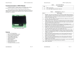
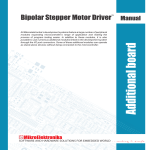
Download USER MANUAL BSD-016
Transcript
Copyright Information
© 2006-2012 Interinar Electronics,LLC. All rights reserved.
This document is furnished exclusively for the customers of Interinar Electronics.
Other uses are unauthorized without written permission of Interinar Electronics.
Information contained in this document may be updated from time to time due to product improvements
and may not conform in every respect to former issues.
USER MANUAL
Disclaimer of Liability
BSD-016
Interinar Electronics is not responsible for special, incidental, or consequential damages resulting from
any breach of warranty, or under any legal theory, including lost profits, downtime, goodwill, damage to
or replacement of equipment or property, or any costs of recovering, reprogramming, or reproducing any
data stored in or used with Interinar products.
Interinar Electronics is also not responsible for any personal damage, including that to life and health,
resulting from use of any of our products. Customer takes full responsibility for any application where
Interinar products are implemented.
Interinar Electronics Technical Support
Email: [email protected]
Website: http://www.interinar.com
SINGLE-AXIS DRIVER
FOR BIPOLAR AND UNIPOLAR STEP MOTORS
INTERINAR ELECTRONICS, LLC.
http://www.interinar.com
rev.1.0
2012
BSD-016 User Manual
Interinar Electronics
USER MANUAL ............................................................................................................................1
1 HARDWARE REFERENCE .....................................................................................................4
1.1.1 OVERVIEW .......................................................................................................................4
1.2
HARDWARE DESCRIPTION ...................................................................................................4
1.2.1 DRIVER FEATURES ...........................................................................................................4
1.3
CONNECTORS ......................................................................................................................4
1.3.1 AVAILABLE CONNECTORS .................................................................................................4
1.3.2 POWER CONNECTOR – J1 .................................................................................................5
1.3.3 MOTOR CONNECTOR – J3 .................................................................................................5
1.3.4 SIGNAL INPUT CONNECTOR – J4 ......................................................................................6
1.3.5 SW2 DIP-SWITCH .............................................................................................................7
1.4
CONNECTING TO BSD-016 ...................................................................................................8
1.4.1 POWER SUPPLY ................................................................................................................8
1.4.2 STEP MOTOR. ..................................................................................................................8
1.4.3 EXTERNAL CONTROLLER ..................................................................................................9
2 OPERATION MODES...........................................................................................................10
2.1.1 OVERVIEW ..................................................................................................................... 10
2.2
SETUP MODE ..................................................................................................................... 10
2.2.1 S1 – MAX MOTOR CURRENT SETUP MODE....................................................................... 10
2.2.2 S2 - IDLE MOTOR CURRENT SETUP MODE...................................................................... 11
2.3
NORMAL MODE .................................................................................................................. 12
2.3.1 N1 – NORMAL OPERATION WITHOUT ICR ....................................................................... 12
2.3.2 N2 – NORMAL OPERATION WITH ICR.............................................................................. 13
2.4
AUTOMATIC IDLE CURRENT REDUCTION (ICR) ................................................................... 13
3 APPLICATION ....................................................................................................................14
3.1
POWER SUPPLY ................................................................................................................. 14
3.1.1 VOLTAGE ....................................................................................................................... 14
3.1.2 CURRENT ....................................................................................................................... 14
3.2
STEPPER MOTOR ............................................................................................................... 14
3.2.1 4-WIRE MOTORS ............................................................................................................ 15
3.2.2 6-WIRE MOTORS ............................................................................................................ 15
3.2.3 8-WIRE MOTORS ............................................................................................................ 16
4 ELECTRICAL AND MECHANICAL SPECIFICATION .............................................................18
4.1
ABSOLUTE MAXIMUM RATINGS .......................................................................................... 18
4.2
ELECTRICAL CHARACTERISTICS ......................................................................................... 18
4.3
EXTERNAL STEP PULSE TIMING PARAMETERS ON STP INPUT .............................................. 19
4.4
SAFETY SUMMARY ............................................................................................................. 19
4.5
TROUBLESHOOTING .......................................................................................................... 19
4.6
TECHNICAL SUPPORT......................................................................................................... 19
5 DIMENSIONS AND MOUNTING..........................................................................................20
BSD-016 User Manual
Interinar Electronics
1 HARDWARE REFERENCE
1.1.1
OVERVIEW
The BSD-016 drives Unipolar and Bipolar Step Motors converting Step and Direction signals from the
external microcontroller to amplified phase currents. Any source of TTL level signals (5V logic) can be
used as a controlling device for BSD-016 driver. The operation with CMOS 3.3V external devices is
possible but not guaranteed. However, we can deliver a special CMOS 3.3V version if requested.
HARDWARE DESCRIPTION
1.2
The BSD-016 is based on powerful DMOS microstepping circuit with internal translator.
The simplicity of the design has advantage in lower number of components making this driver a very rigid
and reliable. Once configured correctly the driver does not require any further adjustments or
maintenance.
Single voltage supply simplifies power requirements and lowers overall system cost.
1.2.1
•
•
•
•
•
•
•
•
•
•
•
•
•
•
DRIVER FEATURES
Bipolar operation
Built-in translator
Phase Current from 95mA to 1500mA (default)
Phase Current from 12mA to 185mA (special order)
Four Stepping Modes: Full, Half, 1/4th, 1/8th (BSD-016-8) or 1/16th (BSD-016-16)
Automatic current decay mode detection/selection
Mixed and Slow current decay modes
Synchronous rectification for low power dissipation
Fixed Off-Time current regulator for Constant Current operation
Internal Under-Voltage-Lock-Out protection
Thermal Shutdown protection
Crossover Current protection
Single Power Supply
Automatic Idle Current Reduction (ICR)
CONNECTORS
1.3
1.3.1
AVAILABLE CONNECTORS
The BSD-016 features following connectors:
•
4
3
POWER CONNECTOR (J1) – power for step motor and circuits on board
•
MOTOR CONNECTOR (J3) – step motor
•
SIGNAL INPUT CONNECTOR (J4) – Enable, Step and Direction signals
BSD-016 User Manual
Interinar Electronics
BSD-016 User Manual
Interinar Electronics
Table 2 – MOTOR CONNECTOR – J3
Terminal #
1
2
3
4
1.3.4
PIN DESCRIPTION
OUT2B
OUT2A
OUT1A
OUT1B
LABEL
PH2
PH1
SIGNAL INPUT CONNECTOR – J4
Connector type: Standard 5mm, 4-pole terminal block, acceptable wires size 26 to 12 AWG.
This connector is used for signals from external microcontroller or PC.
All three inputs feature 4.7kohm internal pull-up resistors to +5V. This way controlling the input is as
simple as shorting it to the Ground. Any sinking device may be used for that purpose.
Specifically, this can be done with jumper, switch, open-collector, open-drain, direct TTL gate output. In
all other cases, it is important to make sure there will be no voltage exceeding +5V or lower than -0.3V
present on any input at any time.
Figure 1. BSD-016
Table 3 – SIGNAL INPUT CONNECTOR – J4
1.3.2
Terminal #
1
2
3
4
POWER CONNECTOR – J1
Connector type: Standard 5mm, 2-pole terminal block, acceptable wires size 26 to 12 AWG.
Table 1 – POWER CONNECTOR – J1
Terminal #
1
2
PIN DESCRIPTION
Negative or Common Voltage Supply
Positive Voltage Supply
LABEL
GND
+VB
Polarity reversal is NOT ALLOWED and will cause permanent damage to the driver.
Exceeding Max Allowed Voltage will result in permanent damage to the driver.
When using a non-stabilized power supply, specifically rectifier/capacitor type, please derate the Supply
Voltage to 70% in order to prevent overvoltage and damage to the driver. This type of power supply can
produce about 1.4 times the rated voltage when the load is not present or very low. This type of
overvoltage condition may occur when the driver is disabled.
1.3.4.1
MOTOR CONNECTOR – J3
Connector type: Standard 5mm, 4-pole terminal block, acceptable wires size 26 to 12 AWG.
Two pairs of terminals belonging to the same phase are located next to each other and labeled on the
board as PH1 and PH2.
Mixing wires of two phases together is prohibited and may result in permanent damage to the driver.
LABEL
ENA
STP
DIR
GND
ENA – Enable.
Input – active LOW.
Internally pulled up to +5V trough 4.7kohm resistor.
When LOW, all motor outputs are ENABLED.
When HIGH, all motor outputs are DISABLED, but translator is still processing Step and Direction signals.
This condition may result in initial position error when using ENABLE to start and stop the motor. The
driver must be ENABLED in advance before Step and Direction changes.
Regardless of operation mode, the driver stops powering the motor, when ENABLE signal is HIGH, absent
or not connected.
1.3.4.2
1.3.3
PIN DESCRIPTION
Enable
Step
Direction
Ground
STP - Step.
Input – active LOW.
Internally pulled up to +5V trough 4.7kohm resistor.
A Low-to-High transition (rising edge) advances the motor one increment. The size of the increment is
determined by MS1 and MS2 (see Table 5). Minimum Step pulse High Time (width) is 1.0us. Minimum
Step pulse Low Time is 1.0us.
1.3.4.3
DIR - Direction.
In case the initial rotation of the motor needs to be reversed and the DIR input cannot be used, swap the
wires of just one phase. Do not swap the wires of both phases at the same time, as this will not reverse
the direction.
Input – active LOW.
Internally pulled up to +5V trough 4.7kohm resistor.
Sets the direction of rotation.
Any changes to this input do not take effect until the next Step rising edge.
If the motor connections follow correct phase order, then when this input is Low, the direction will be
Clockwise and when High, Counterclockwise. Swapping wires of just one phase will also reverse direction.
5
6
BSD-016 User Manual
1.3.4.4
Interinar Electronics
GND - Ground.
BSD-016 User Manual
Table 5 – Microstepping Resolution Truth Table
Signal Ground – return path for all three inputs.
Should not be used as power ground.
1.3.5
Interinar Electronics
SW2.3
(MS1)
ON
OFF
ON
OFF
SW2 DIP-SWITCH
SW2.4
(MS2)
ON
ON
OFF
OFF
RESOLUTION–STEP
BSD-016-8
BSD-016-16
FULL
FULL
HALF
HALF
QUARTER
QUARTER
EIGHTH
SIXTEENTH
EXCITATION MODE
BSD-016-8
BSD-016-16
2 PHASE
2 PHASE
1-2 PHASE
1-2 PHASE
W1-2 PHASE
W1-2 PHASE
2W1-2 PHASE
4W1-2 PHASE
The 4-position dip-switch is used in process of setting motor parameters and configuring the driver. Each
individual switch is numbered from 1 to 4. The driver is shipped with all switches in OFF state as default.
CONNECTING TO BSD-016
1.4
Table 4 – Power-Up Mode Condition Truth Table
MODE
S1
S2
N1
N2
1.3.5.1
.1
ON
ON
OFF
OFF
SW2.x
.2
.3
OFF
OFF
ON
OFF
OFF
OFF
ON
OFF
.4
OFF
OFF
OFF
OFF
MODE DESCRIPTION
SETUP – VREF(MAX) (Max Motor Current)
SETUP – Idle VREF(ICR) (Idle Motor Current)
NORMAL OPERATION no ICR
NORMAL OPERATION with ICR
SW2.2 – Idle Motor Current Setup or Normal Operation with ICR.
Default: OFF
Allowed position during boot up: ON, OFF
Allowed position in normal operation: ON, OFF
Used in modes: S2, N2.
Function during boot up: see Table 4.
1.3.5.3
NEVER CONNECT OR DISCONNECT ANY WIRE FROM BSD-016 WHILE POWER IN ON.
1.4.2
DISCONNECTING MOTOR WHILE POWER IS ON WILL CAUSE
PERMANENT DAMAGE TO THE DRIVER.
SW2.3 – Microstepping MS1.
SW2.4 – Microstepping MS2.
Default: OFF
Allowed position during boot up: ON or OFF
Allowed position in normal operation: ON or OFF
Used in modes: N1, N2.
Function during boot up: has no effect.
Function during normal operation: see Table 5.
7
STEP MOTOR.
The step motor should be connected to the J3 terminal block. Labels are placed next to the terminals in
two groups, clearly marking each phase. There is no reference to the beginning or the end of each
phase.
Make sure that all four motor wires are tightly connected and there is no possibility of accidental
disconnection. For 6- and 8-wire motors, all unused wires must be insulated separately. This is especially
important when additional connectors are used between the driver and the motor.
Default: OFF
Allowed position during boot up: ON or OFF
Allowed position in normal operation: ON or OFF
Used in modes: N1, N2.
Function during boot up: has no effect.
Function during normal operation: see Table 5.
1.3.5.4
POWER SUPPLY
The power supply selection should be based on step motor specification and maximum allowable voltage
for the driver. There is no need for stabilized power supply, however it is recommended to use it.
When using a non-stabilized power supply, specifically rectifier/capacitor type, please derate the Max
Allowed Voltage to 70% in order to prevent overvoltage and damage to the driver. This type of power
supply can produce about 1.4 times the rated voltage when the load is not present or very low. This type
of overvoltage condition may occur when the driver is disabled.
SW2.1 – Motor Current Setup.
Default: OFF
Allowed position during boot up: ON, OFF
Allowed position in normal operation: OFF
Used in modes: S1, S2.
Function during boot up: see Table 4.
1.3.5.2
1.4.1
8
BSD-016 User Manual
1.4.3
Interinar Electronics
BSD-016 User Manual
Interinar Electronics
2 OPERATION MODES
EXTERNAL CONTROLLER
BSD-016 requires external Step, Direction and Enable signals connected to terminal block J4. The fourth
pole is used for signal ground and should not be used as power ground. All three inputs are pulled-up
internally to +5V through 4.7kohm resistors. The TTL (5V level) interface, open-collector, opto-coupler,
relay and switch can be used directly in connection with this port (see Figure 2). The CMOS 3.3V
operation is possible but not guaranteed.
If not used, the Direction input may be left disconnected.
The Enable input, if not used, may be permanently shorted to GND if the driver works in N2 mode with
IRC and the Idle current is set low. Living Enable shorted for prolonged time with current set high may
lead to motor and driver overheating.
2.1.1
OVERVIEW
Prior to normal operation the BSD-016 requires a simple setup. Possible modes are listed below.
Setup Mode
o
S1 – Max Motor Current Setup
o
S2 – Idle Motor Current Setup for ICR
Normal Mode
o
N1 – Normal Operation without ICR
o
N2 – Normal Operation with ICR
Regardless of operation mode, the BSD-016 always stops powering the motor when ENABLE signal is
HIGH, absent or not connected.
C
I
G
O
L
L
T
T
2.2
In Setup mode, the BSD-016 will set and store:
- Max Motor Current
- Idle Motor Current
R
O
T
C
E
L
L
O
C
N
E
P
O
R
E
L
P
U
O
C
O
T
P
O
4
J
R
I
D
,
P
T
S
,
A
N
E
O
T
(
)
2.2.1
S1 – MAX MOTOR CURRENT SETUP MODE
The max phase current must be set first. The phase current can be obtained directly from the label of the
motor, data sheet or manufacturer. The BSD-016 is a CONSTANT CURRENT driver. The phase current is
all you need to know to setup the driver.
To adjust and keep the phase current at correct level the BSD-016 uses reference voltage VREF, always
present on TP1 (Test Point located right below dip-switch SW2). The relation between VREF and max
phase current IMAX can be described as follows:
Y
A
L
E
R
H
C
T
I
W
S
(
4
#
N
I
P
4
J
D
N
G
O
T
Figure 2. Typical Input Driving Methods.
SETUP MODE
VREF(MAX) [V] = k x IMAX [A]
)
Where:
- VREF(MAX) in Volts
- IMAX in Amperes
- k – coefficient, based on value of the sensing resistors R6, R7
k=2.64 for 0.33ohm resistors marked as R33 for standard version 95mA to 1500mA
k=21.6 for 2.7ohm resistors marked as 2R7 for special version 12mA to 185mA
Example:
- Motor is labeled 0.91A, BSD-016 driver with 0.33ohm sensing resistors
VREF(MAX) = 2.64 x 0.91A = 2.4V
This VREF(MAX) value must be used during motor current setup procedure.
The S1 mode can be entered only during boot up (power up) process, while the SW2.1 dipswitch is in ON and SW2.2 is in OFF position (see Table 4).
9
10
BSD-016 User Manual
Interinar Electronics
BSD-016 User Manual
Enter mode S1:
- Turn OFF the power
- Turn ON switch SW2.1
- Turn OFF switch SW2.2
- Switches SW2.3 and SW2.4 are irrelevant in this mode
Interinar Electronics
SW2
SW2
S2
-
S1
-
Connect Volt Meter between TP1 and GND
Turn ON the power
Observe, as the VREF will rise slowly from 0V towards 4.0V.
When VREF reaches calculated value slide the SW2.1 switch back to OFF position
If you missed the right moment, then let the voltage go up. Once it reaches 4.0V, it will reset to
0V and start rising up again.
If you switched it OFF at wrong value, then you have to turn OFF the power and repeat the
entire process.
Exit from mode S1:
- Move SW2.1 to OFF position
- Turn OFF the power
Actual storing of the VREF value to the EEPROM occurs while the SW2.1 moves from the ON to the OFF
position. However, storing can be performed only once per each cycle. That means, in case of mistake,
the whole procedure must be repeated, starting from turning OFF the power and then reentering the S1
mode again.
The driver will not function correctly until the next power OFF to ON transition.
2.2.2
S2 - IDLE MOTOR CURRENT SETUP MODE
-
Connect Volt Meter between TP1 and GND
Turn ON the power
Observe, as the VREF will rise slowly from 0V towards VREF(MAX) value set in S1 mode.
When VREF reaches calculated value slide the SW2.1 switch back to OFF position
If you missed the right moment, then let the voltage go up. Once it reaches VREF(MAX), it will reset
to 0V and start rising up again.
If you switched it OFF at wrong value, then you have to turn OFF the power and repeat the
entire process.
Exit mode S2:
- Move SW2.1 to OFF position
- Turn OFF the power
Actual storing of the VREF value to the EEPROM occurs while the SW2.1 moves from the ON to the OFF
position. However, storing can be performed only once per each cycle. That means, in case of mistake,
the whole procedure must be repeated, starting from turning OFF the power and then reentering the S2
mode again.
The driver will not function correctly until the next power OFF to ON transition.
2.3
NORMAL MODE
The BSD-016 will function properly only in Normal Mode N1 or N2.
To access N1 the SW2.1 and SW2.2 must be in OFF position and after power up the driver will enter
Normal Mode N1 based on stored parameters.
To access N2, the SW2.1 should be OFF and SW2.2 ON. The position of the SW2.3 and SW2.4 is
irrelevant.
SW2
This setup must be performed only, if user intends to use BSD-016 with ICR (Automatic Idle Current
Reduction). Calculation for VREF(ICR) is the same as for VREF(MAX).
The S2 mode can be entered only during boot up (power up) process while the SW2.1 and SW2.2
dip-switches are ON (see table 4).
Enter mode S2:
- Turn OFF the power
- Turn ON switches SW2.1 and SW2.2
- Switches SW2.3 and SW2.4 are irrelevant for this mode
N1
2.3.1
N1 – NORMAL OPERATION WITHOUT ICR
The BSD-016 energizes the motor only when ENABLE signal is low. Motor will start rotate when the STEP
pulse is present on STP input. The direction of the rotation depends on signal level present on DIR input.
Parameters necessary for N1 Operation Mode:
- Perform S1 setup
- Cycle the power OFF/ON
11
12
BSD-016 User Manual
2.3.2
Interinar Electronics
Interinar Electronics
N2 – NORMAL OPERATION WITH ICR.
The BSD-016 energizes the motor only when ENABLE signal is low. Motor will start rotate when the STEP
pulse is present on STP input. The direction of the rotation depends on signal level present on DIR input.
If the STEP pulse is absent for period longer than 2 seconds, the driver will enter ICR mode and lower
the phase current to the level set during S2 setup.
Parameters necessary for N2 Operation Mode:
- Perform S1 setup
- Perform S2 setup
- Set SW2.1 OFF and SW2.2 ON
- Cycle the power OFF/ON
SW2
N2
2.4
BSD-016 User Manual
AUTOMATIC IDLE CURRENT REDUCTION (ICR)
The BSD-016 driver is equipped with Automatic Idle Current Reduction (ICR) circuitry. The main purpose
of using this feature is the reduction of the heat dissipated in the motor and driver during the time when
the motor stays idle in one position (without moving), for prolonged time. Driving the motor at 100% its
rated current while still standing will not only produce the heat in the motor, which may lead to
overheating, but it is a waste of energy. In majority of applications, the torque needed to hold the load in
the position is minimal compared to the torque needed to move the load from one position to another.
Only a handful of applications require producing the holding torque at the same level during both rotation
and stand still periods.
Automatic Idle Current Reduction is available in N2 mode. It is activated 2 seconds after the last change
on the STP input. When turned ON it will lower VREF from VREF(MAX) to VREF(ICR).
The VREF is restored to VREF(MAX) within 700us after arrival of the next step pulse on STP input.
The Idle Current may be set to any value in range from 0 to 100% of the IMAX.
In other words, you may adjust VREF(ICR) to any value in range from 0 to 100% of the VREF(MAX).
Automatic Idle Current Reduction IS NOT AVAILABLE IN SETUP MODES S1 or S2.
3 APPLICATION
3.1
POWER SUPPLY
The BSD-016 is a Constant-Current driver, which means that it will maintain the phase current regardless
of the voltage applied to the driver. However, this statement implies certain limitations described below.
3.1.1
VOLTAGE
The BSD-016 works most of the time in Constant-Current Mode by switching the voltage on motor
terminals (chopping), while monitoring and maintaining the level of the phase current. The driver will
stay in Constant-Current Mode as long as the voltage applied to the power terminal is higher than the
rated voltage of the motor. For example, motor label shows 12V. The BSD-016 will work in ConstantCurrent Mode only if the power supply voltage is above 12V and lower than max allowed for the driver
30V. If the power supply delivers 12V or less, the driver will work in Voltage Mode. In such case, the
driver will no longer maintain the phase-current, which will be limited directly by the resistance of the
motor’s windings.
Both regulated and unregulated power supplies may be used.
A regulated power supply can be rated up to max allowed voltage for the BSD-016 which is 30Vdc.
However, unregulated power supply cannot exceed 21Vdc because it is rated at full load current. At
lesser loads, like when the driver is disabled, the actual voltage of the power supply may be up to 1.4
times higher, which will exceed the maximum voltage allowed for the driver.
3.1.2
CURRENT
The BSD-016 requires no more current than the twice of the phase-current (2 x Iph) of the motor.
There is a common misconception, based on wrong measurements, that in real application only fraction
of that current is being utilized. However, these measurements are performed using RMS values, which
lead to mistakes in selecting the power supply. If the power supply is not capable of supplying enough
current, then the driver will not be able to deliver it to the motor. As a result, the motor will not produce
the torque specified in data sheet.
The current needed for logic on the board is marginal and may be ignored in this calculation.
3.2
STEPPER MOTOR
The BSD-016 is based on DMOS technology and despite the fact that it features output protection it will
be damaged if not properly connected to the motor. Common mistakes include phase wire mixing and
connecting motor directly to VB or Gnd.
Only two-phase stepper motors may be used. That includes both bipolar and unipolar motors. Bipolar
motors are always 4-wire type. Unipolar motors come in 6- or 8-wire version, which gives additional
flexibility in selecting performance.
Most of “thin-can” 2-phase motors have different switching sequence and will not work with BSD-016
(please compare switching sequence in motor data sheet).
The 5-phase motors cannot be used with BSD-016.
NEVER CONNECT OR DISCONNECT THE MOTOR WHILE THE POWER IS ON.
INSULATE UNUSED MOTOR LEADS SEPARATELY.
DO NOT CONNECT ANY MOTOR LEADS TO GROUND OR POWER SUPPLY.
13
14
BSD-016 User Manual
3.2.1
Interinar Electronics
BSD-016 User Manual
Interinar Electronics
4-WIRE MOTORS
This type of motor can be connected only one way. See drawing below. Swapping two wires of just one
phase will cause motor to rotate in opposite direction.
J1
J4
STEP MOTOR
J1
J4
BSD-016
STEP MOTOR
BSD-016
SW2
Figure 5. Unipolar connection of 6-wire motor.
SW2
Table 7 – Parameters for 6-wire motor
Figure 3. Bipolar 4-wire motor connection.
MODE
Bipolar-Series
Unipolar
Table 6 – Parameters for bipolar 4-wire motor.
MODE
Bipolar
3.2.2
POWER
100%
CURRENT
100%
VOLTAGE
100%
TORQUE
100%
POWER
100%
100%
CURRENT
70%
100%
VOLTAGE
140%
100%
TORQUE
140%
100%
6-WIRE MOTORS
Motors with 6 leads can be connected in two different ways:
1. Bipolar-Series connection- center tap is not used. Both ends of each phase are connected to the driver.
In series connection, motor should be operated at 70% of the rated current. Running motor at full rated
current will saturate and overheat the motor. The series connection is preferred method because it
produces less heat in the driver and produces higher torque.
3.2.3
8-WIRE MOTORS
This motor can be connected in three ways.
1. Bipolar-Series connection. Gives more torque at lower speeds. In series connection, motor should be
operated at only 70% of the rated current because using twice as large winding of each phase produces
rated torque at lower current. Running motor at full rated current will saturate and overheat the motor.
J1
J4
J1
J4
STEP MOTOR
STEP MOTOR
BSD-016
BSD-016
SW2
SW2
Figure 4. Bipolar-series connection of 6-wire motor.
The BSD-016 may not be able to drive some motors in series connection. Specifically, construction of 7.5
degree tin-can motors requires different switching sequence. In such case, center tap connection must be
used.
Unipolar connection – one end of each phase is insulated. The other end and center tap are connected to
the driver. The driver should be adjusted to full rated current of the motor. This connection works better
at higher speeds.
15
Figure 6. Bipolar-series connection of 8-wire motor.
Unipolar connection – only one pair of each phase is used. This connection works better at higher
speeds.
16
BSD-016 User Manual
Interinar Electronics
Interinar Electronics
4 ELECTRICAL AND MECHANICAL SPECIFICATION
J1
J4
BSD-016 User Manual
4.1
ABSOLUTE MAXIMUM RATINGS
STEP MOTOR
Table 9 – Absolute maximum ratings for BSD-016 driver-controller.
BSD-016
CHARACTERISTIC
Supply Voltage
Motor Current
Logic Input Voltage
Operating Ambient Temperature
SW2
Figure 7. Unipolar connection of 8-wire motor.
4.2
Bipolar-Parallel connection. Motor should be run at 1.4 of the rated current. This connection is not
recommended as higher current generates more heat in the driver and motor.
CHARACTERISTIC
Motor Supply Voltage
Motor Current
Logic Input Voltage
Control Analog Input – ANA
Analog DC Voltage
BSD-016
Figure 8. Bipolar-parallel connection of 8-wire motor.
Table 8 – Parameters for 8-wire motor.
17
CURRENT
70%
140%
100%
VOLTAGE
140%
70%
100%
SYMBOL Condition Min Typ
Motor Outputs
VB
Operating
8
Standard
95
IOUT
Special
12
Control Logic – Enable, Step, Direction, STA
VIH (1)
3.5
VIL (0)
-
VANA
0
Protection
Crossover Dead Time
tDT
100
Thermal Shutdown Temperature
Tj
Thermal Shutdown Hysteresis
TjHYS
Automatic Idle Current Reduction (ICR)
ICR ON delay time after last Step pulse
tICRon
ICR OFF delay time after first Step pulse
tICRoff
Idle current reduction in % of IMAX
IICR
0
SW2
POWER
100%
100%
100%
UNITS
V
A
V
°C
ELECTRICAL CHARACTERISTICS
STEP MOTOR
MODE
Bipolar-Series
Bipolar-Parallel
Unipolar
RATING
30
+/- 1.5
-0.3 to +5.5
-20 to 85
Table 10 – Electrical characteristics for BSD-016 driver-controller.
J1
J4
SYMBOL
VB
IOUT
VIN
Ta
TORQUE
140%
140%
100%
18
Max
UNITS
30
1500
185
V
mA
mA
1.5
V
V
-
5
V
475
165
15
800
-
ns
°C
°C
2
-
700
100
s
us
%
BSD-016 User Manual
4.3
Interinar Electronics
BSD-016 User Manual
Interinar Electronics
EXTERNAL STEP PULSE TIMING PARAMETERS ON STP INPUT
5 DIMENSIONS AND MOUNTING
Table 11 – Step pulse timing parameters.
CHARACTERISTIC
STEP – Minimum HIGH pulse width
STEP – Minimum LOW pulse width
Setup time
Hold time
Maximum frequency
4.4
SYMBOL
tA
tB
tC
tD
fSTP
TYP
1
1
200
200
500
UNITS
µs
µs
ns
ns
kHz
SAFETY SUMMARY
Always remove power and discharge the circuit before touching it.
This module contains parts susceptible to damage by ESD (Electrostatic Discharge). The BSD-016 must
be handled in accordance to procedures specified for ESD devices.
Do not make any modification to the board or components.
DO NOT PLUG/UNPLUG ANY WIRES AND CONNECTORS TO/FROM THE MODULE WHILE
POWER IS ON.
4.5
TROUBLESHOOTING
If driver does not function according to previously set mode, turn it off and make sure that the SW2.1 is
in OFF position. Turn ON the power again and observe presence of +5V (min 4.5V, max 5.2V) on C25. If
min of +4.5V is not present, then contact our Technical Support by sending email to
[email protected]
4.6
Figure 9. Mechanical dimensions.
TECHNICAL SUPPORT
Interinar Electronics is happy to respond to any question or concern regarding the BSD-016 or any other
product it manufactures or sells. Contact Technical Support Staff by sending email to
[email protected]
19
20
BSD-016 QUICK SETUP GUIDE
First, decide in which mode the driver should work::
o
N1 – Normal Operation no ICR - driver without Idle Current Reduction
o
N2 – Normal Operation with ICR - driver with Idle Current Reduction
Second, perform setup necessary for selected mode.
N1
S1
N2
SETUP FOR DRIVER – NO ICR
SETUP
MAX
MOTOR
CURRENT
1
SW2.1
ON
SW2.2
OFF
2
POWER
ON
3
MEASURE
VREF
4
SW2.1
OFF
5
POWER
OFF
6
SW2.1
OFF
SW2.2
OFF
7
POWER
ON
N1
NORMAL
MODE
NO ICR
11
SW2.1
OFF
SW2.2
ON
12
POWER
ON
N2
NORMAL
MODE
WITH
ICR
SETUP FOR DRIVER – WITH ICR
S1
SETUP
MAX
MOTOR
CURRENT
1
SW2.1
ON
SW2.2
OFF
2
POWER
ON
3
MEASURE
VREF
S2
SETUP
IDLE
MOTOR
CURRENT
6
SW2.1
ON
SW2.2
ON
7
POWER
ON
8
MEASURE
IDLE
VREF
4
9
SW2.1
OFF
SW2.1
OFF
5
10
POWER
OFF
POWER
OFF


