1
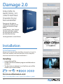
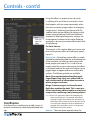
Damage User Manual
Contents
3 Installation
4 Controls
6 Controls - cont’d
8 Controls - cont’d
10 Controls - cont’d
12 Controls - cont’d
14 Controls - cont’d
16 Controls - cont’d
18 Controls - cont’d
20 Troubleshooting
®
Damage 2.0
Deface, Defile, Dismantle, Destroy. Isn’t
it time for more Visual
Devastation for your
hard-earned dollar?
Damage sets the industry
standard for simulating visual
analog and electronic image
defects
in your footage. Now, Damage
2.0 adds more effects and 64
bit native operation and 32 bitper-channel processing.
Resources
Video Tutorials
Check out project techniques
from DigiUsers just like you.
View video tutorials
The Reviews
See what others are saying about
DE’s latest releases, plugin effects,
and more.
You do good work...we can fix that.
Installation
System Requirements:
Damage 2.0 is a plugin for Adobe After Effects, Premiere Pro CS4 and CS5,
Final Cut Pro, Autodesk, Combustion, Boris Red, and Grass Valley Edius.
It has been tested with Snow Leopard and Windows 7.
Read the reviews
Project Gallery
DE software and plugins in action.
Installing
1 Locate the Install file.
2 Double-click the installation program and follow the instructions.
3 The first time you attempt to run FreeForm, you will be
asked for your serial number.
Search, view, and download the latest
presets and videos or submit your own.
For more information visit:
Visit project gallery
http://www.digieffects.com/support/installation_guide
23
®
Controls
The Damage plugin simulates video malfunction. For all effects “About”, “Reset”, and “Animation Presets”
function in the same manner.
Reset
Resets the parameters to their factory default.
Options
Use this link to bring up the registration dialog
and enter your key code. After you’re registered,
this shows information about Digieffects and the
Damage 2.0 plugin version.
About
Shows information about Digieffects and the
Damage plugin version.
Animation Presets
Contain groups of parameter settings you would
like to keep for future use. The list is empty until
you save a group of parameters as a Preset.
Source Blend - Control how much unaffected
target layer you see mixing with the effect.
Some Common Parameters-
Artifact
There are a few parameters that you will see in
nearly all of the effects in Damage 2.0. These
parameters function in the same way in each
instance.
Random Seed - The mathematical engine that
drives the chaotic and erratic parameter fluctuations over time are all starting with this value.
It’s important to note that this value does not
increase the “randomness” as the number gets
larger. Various values cause different mathematical routines and because the result is also dependent on how the parameter values in the rest
of the controls are set up, these Random Seed
values do not ‘scale’ on any sort of continuum so
much as introduce a different factor to calculate
from. Experimentation with different values until
you see what you want is probably the best advice for this control.
®
Artifact is an effect designed to simulate digital
image decode or transmission errors usually associated with dropped data from satellite transmissions or digital video playback errors and it
does so very convincingly. (It’s usually good to
warn the client before previewing the effects as
they may question your technical quality control.)
MPEG errors such as hanging frames and blacked
out frames (data packet loss) and DCT (Discrete
Cosine Transform, which means…uh….well, let’s
just say it’s the blocks.), blocks misplaced in the
image and missing color information all contribute to an effect that will have many uses, not the
least of which might be just driving your favorite
digital video engineer nuts…
Parameters
Operation Type-There are six different operations to choose from inside of Artifact:
Normal – This mode uses all the operations available inside Artifact in combination to create an
effect similar to a digital VTR with dirty heads or a
failing digital feed of some kind.
Burst Mode – Burst uses the same combination
of operations as Normal mode, but applies them
in much higher density. Using keyframing within
your host application, you can use burst mode to
bring a clip in from complete digital distortion…
or keyframe the effect in at the end of a clip to
represent a lost digital feed.
JPG Noise – JPG Noise consists of visual artifacts
made up solely of multi-color blocks with varying detail inside of them…simulating improperly
decoded picture information being replaced by
insufficient error correction. This operation can
be used to simulate MPEG-2 macroblock glitches,
such as those seen when a scratched DVD is
played.
Blackout – Choosing Blackout will make the areas
of the image affected by Artifact be simply black.
There will be no colors or detail inside the affected areas, only black. When data is lost in many
kinds of digital feeds, the blocks may simply come
up as black.
Recolor – Recolor creates affected areas with simply random color change. The defects will show
only as tinted areas over the existing image.
Shifter – Shifter is useful for creating the look of
a digital video decode failingwithout having as
busy a pattern as you might have when you use
Normal or JPG Noise modes. Shifter simply moves
image content out of place into the affected areas
to create a somewhat more subtle but still disconcerting image problem.
Codec Artifacting – Use the properties under this
45
heading to set the intensity, frequency and duration of the defective episodes and to choose the
amount of freezing “frame stutter” or some might
call it a “frame dropping” look.
Artifact Amount –Surprisingly, this property
controls how intensely (the amount) the defect
is generated on your clip. The scale is 0-100 with
zero disabling the effect altogether. Extended
range of 0-200 is available by typing in the value,
or dragging the value field. If you adjust this
property to a very low value, your effect may not
be visible in the frame you have paused. It’s best
to scrub or preview the clip to ensure you have
the effect you want.
Artifact Frequency – Another surprise, this property controls how often the defect repeats itself.
Again, value range is 0-100 with 0 being never
repeating and 100 and above being never…uh…
not repeating.
Average Duration – Adjusting Average Duration
values affects how long each repeating defect
‘attack’ actually lasts…on average. 0-100 range
running from no duration at all to a nearly solid,
constant stream of the effect.
Freezing – Often, if a digital transmission is failing in some fashion, the receiving device will just
hold frames in a frame buffer until it can again,
resume receiving packets. This results in what
appears to be intermittent freeze frames in the
midst of all these other failures. Adjusting the
Freezing property controls how often the clip
freezes as if it has lost its connection.
Downgrader– These controls mimic the lower
resolution images that can occur when video is
only partially decoded, or was simply sent at a
very low resolution and scaled up in some less
than pristine fashion.
DownRes. Factor – This control will decrease the
apparent resolution of your footage. Details will
®
Controls - cont’d
become less distinct and the quality of the image will be affected in proportion to the value
you choose between 1 and 32. A value of 1 will
not affect the image much at all and a value of
32 would be similar to viewing your television
through a bottle of castor oil...that hasn’t been
dusted in some time.
Re-interpolate Res. – As your footage loses
resolution and detail, some devices will attempt
to ‘smooth’ the remaining detail so the jagged
blocks are less objectionable. A setting of ‘None’
will do no smoothing, ‘Horizontal’ will not smooth
vertical edges, and ‘Horizontal + Vertical’ will
smooth in both directions.
Lo-Fi Color – Many forms of digital compression
store some color channel signals as lower resolution samples that are processed separately, and
often errors in playback and decoding can affect
different parts of the file in different ways. The
color precision of your image will get increasingly
inaccurate and crude as you increase this setting
from 0-8.
Blockade
Blockade’s main role is simulating low fidelity
camera feeds from maybe a cel phone…or PDA.
The effect places random blocks of slightly tinted
color around your image, which creates the impression that these areas are not being faithfully
color sampled, which is a common occurrence
in many of the low resolution video cameras in
phones as the video has to be highly compressed
to be transmitted over the cellular phone…and
then stored in as small a file as is practical.
Parameters
Freeze – The Freeze properties affect how the
processed clip will infrequently “hang” on a frame,
simulating a possible interruption in data trans®
mission.
Freeze Recurrence – Recurrence controls how
frequently the video will freeze. A higher value
here will result in less moving video in your affected clip and a greater amount of time spent
“hanging” on a frame. More frequent freezes
might represent a less reliable video source, or a
more distant or strained transmission…
Freeze Duration –The duration controls how
long the video stays frozen during each occurrence. The higher the value, the longer the freeze
duration. The frame that would normally occur
during the freeze will not be shown, the video
will continue at the point it resumes playback, as
if the data was lost as opposed to being ‘paused’.
This value represents the number of frames of
freeze duration, but note that it is affected by
the Random Seed, Freeze Recurrence and Freeze
Duration Variance values.
Freeze Duration Variance – A completely predictable pattern of freeze occurrence and duration doesn’t look like a defect so much as a video
strobe (which wasn’t the most compelling effect,
even in the late 1980’s when for some reason it
was inexplicably popular), so some variation can
help sell the “defectiveness” of the effect. Increasing this value will vary the Freeze Duration +/- in
increasing amounts as the value increases.
Stutter – Stutter properties make your clip seem
to jump around in time, as if some data was lost
and the clip is trying to go back and play a small
bit over again, or is skipping over some temporal
data that is lost, making the video “jump ahead”
in time.
Stutter Recurrence – Recurrence controls how
frequently the video will stutter. A higher value
here will result in more skipping around moving
video in your affected clip and a greater amount
of time spent “out of order” relative to smooth
playback. The more frequently stutter recurs, the
more erratic any motion seems.
Stutter Duration – The duration controls the
length of the segments that stutter out place during each occurrence. The higher the value, the
longer the stutter segment duration. This value
represents the number of frames of stutter duration, but note that it is affected by the Random
Seed, Stutter Recurrence and Stutter Duration
Variance values.
Stutter Dur. Variance – Predictable patterns of
any of these properties are best avoided to better sell the effect as a “defect.” Variations in the
67
duration of the Stutter property can help sell the
effect. Increasing this value will vary the Stutter
segment Duration +/- in increasing amounts as
the value increases.
Timing – The Timing parameters control the temporal properties of the blocks in “Blockade”
Blockiness Recurrence – Recurrence controls
how frequently blocks will appear. A higher value
here will result in more frequent blocks in your
affected clip. More frequent and intense blocks
might represent a more aggressively compressed
video source, or a more primitive camera system.
Blockiness Duration – The duration controls
the length of each occurrence of blockiness. The
higher the value, the longer each block occurrence is on screen. This value represents the number of frames of stutter duration, but note that it
is affected by the Random Seed, Blockiness Recurrence and Blockiness Duration Variance values.
Blockiness Dur. Variance –Variability of all the
factors inside the Blockade effect help to portray
the results as unintended defects. Increase this
value to increase the fluctuation in length of each
occurrence of “blockiness.”
Blockiness Speed – Blockiness Speed controls
how quickly the blocks change form. This effect
tends to look more like a cel phone, PDA, or web
camera when the speed is set for relatively fast
changes.
Sizing –These parameters have control over the
size of the blocks and the size of the size of the
groupings.
Block Amount –The Block Amount parameter
controls the amount of picture affected by the
Blockade effect. For a simulation of crude palettes
evident in aggressively compressed video from
hand held devices, a very high value which covers
the entire frame works very well.
Block Size – This parameter controls the vertical
®
Controls - cont’d
size of the blocks in your image.
Striping – The Striping parameters control the
horizontal aspect of the block artifacts in your
image.
Stripe Length – The Stripe Length parameters
control the horizontal size of the block artifacts in
your image.
Stripe Len. Variance – Increasing this value will
vary the Stripe Length +/- from occurrence to
occurrence in increasing amounts as the value
increases.
Coloring – The Coloring parameters control the
color properties of the Blockade effect. All the
parameters are interdependent and the possible
combinations of settings is nearly infinite. However, note that often more subtle parameter settings creates the most realistic effect.
Block Color – The color palette here defines the
color of mosaicing / color-blocking. You can pick
a color from a palette, or eyedropper a color from
your target layer. To what degree the color chosen here influences theblocks in your clip is controlled by the ‘Color Conformance’s slider.
Color Conformance – At the highest Color Conformance values, the blocks take on the color that
is set in the Block Color parameter. At the lower
settings, that color influences the content in your
target layer without obscuring it. This is one parameter where often, less is more.
Color Change – The Color Change parameter
determines whether the blocks take more of the
source colors (at the lowest Color Change values),
or randomly deviate from the colors present in
the target layer. High values here will produce vibrant colors, that seem to be less associated with
the picture content as you increase the value...
again a case where often less is more.
®
Color Change Weight – The Color Change Weight
parameter at lower values allow the blocks to
have a mixture of source image colors and colors
that deviate from the target layer’s palette. On
the other hand, high Color Change Weight values
causeless of the original source image to modulate the block colors, so the effect looks like solidcolor blocks from another planet have invaded
the clip, replacing the source.
Transparent Blocks – This parameter controls
the balance between square, opaque areas of
mosaic and more rectangular bands of rectangles.
At minimum values, the effect is mostly mosaic,
while higher values result in layering of more
transparently colored blocks.
Alpha Handling
Don’t Preserve Alpha – Blockade will affect the
entire frame without regard for any alpha channel
transparency information.
Mostly Preserve Alpha – Blockade will use the
alpha channel as input for its computation, but
will not necessarily confine its operation to the
opacity defined by the alpha channel.
Completely Preserve Alpha – Blockade will only
function where the affected clip is opaque and
blocks will appear at a transparency level that corresponds to the target clip’s alpha transparency.
value will vary the Blockiness Duration +/- from
occurrence to occurrence in increasing amounts
as the value increases.
Interference
Interference is a unique effect inside DigieffectsDamage because of its ability to give the
impression that your video clip is interlaced and
being displayed on a Cathode Ray Tube monitor. Most television signals used in broadcasting
have traditionally been interlaced. This system of
handled individually with parameters labeled (E)
for the ‘even field’ and (O) for the ‘odd field’.
Parameters
scanning two ‘fields’ of horizontal lines (each field
made up of every other line in the image, usually
referred to as “Upper/Lower”, “Odd/Even”, or even
“A/B”) to make each ‘frame’ of video is both a form
of analog video compression, and the reason why
interlaced video motion looks smoother than progressive video or film motion. This effect will be
particularly useful for instances when you want to
specifically portray inexpensive television receivers, stereotypical industrial video camera signals,
or even night vision. Each field’s attributes can be
89
Fields Setup
Size – Set the vertical size for each ‘field’ here. A
very effective way to utilize this parameter is to
set one field for a height of one and set its Luminance setting relatively dark creating the ‘border’
between the ‘scanlines’, while using the other
‘field’ for your picture content with a size setting
of 2-4.
Process Input – While the Source Blend value
controls the overall ratio between the unaffected
source image vs. the effect-processed image,
the Process Input controls how aggressively the
source image gets processed in each of the two
pipelines (one for E and one for O).
Luminance – This value influences the luminance
level of each ‘field’ independently. Setting the two
fields for different values will accentuate the ‘scanline’ look of your results.
Tint – Check the box to Tint your video to help
create effects like simulated night vision.
Tint Color – Pick the color of your Tint using the
eyedropper or pick from the palette from clicking
on the color swatch.
Noise
Noise Level – Add noise to the each field separately with this value.
Chroma Noise – Check the Chroma Noise box to
add color to the noise generated for each field.
Decay Amount – Decay Amount controls the
number of re-processing or feedback-loops of the
effect. Higher value here means the processed image gets its color values ‘dirtied’ even further, with
more of the information in the mid- to hirange
getting lost. Imagine running a photocopy of a
®
Controls - cont’d
photocopy again and again…or possibly a VHS
dub of a dub. The effect is highly-dependent on
source footage, but usually causes some blooming
of mid- and highlights.
Smear –When Distortion is present (see the
Modulation section), it is fed back into the re-processing loop. The effect gets especially interesting
when there are subtle, varying amounts of distortion at medium to high Decay Amount values.
Modulation
Distortion Method – There are several modes of
distortion that can be assigned to each field independently.
Shift translates the entire ‘field’ (as defined by your
E and O settings) to the right, that can be used to
simulate symptoms like transmission delay or field
dominance reversal.
Linear applies linearly-varying amounts of shift
from the top of the screen to the bottom of the
screen, introducing a diagonal error through the
‘field’.
Noisy mode is very random, such that each scanline is translated left-right by erratic and changing
values.
Sawtooth mode applies a sawtooth-wave to vary
the amount of left-right shifting of ‘scanline’ content.
Wave mode is similar to Sawtooth, except that
the waveform creates a more rounded or curved
displacement .
Horiz. Adj. – Controls the extent of left-right
modulation, as defined by the mode above. High
values here combined with high Influence result
in the greatest distortion. Note: when a scanline is
distorted and shifted ‘outside’ the screen area, the
result is that scanline becomes black in the area
left behind by the movement of the ‘scanline’.
Influence – Influence affects the Horizonal shift®
ing as defined above, but depends on the Distortion Mode. At zero, there will be no shifting at all.
Low Influence values mean the modulation effect
will be subtle, even if the Horizontal Adjustment
values are high. In some of these modes, you can
think of Influence as the ‘Coarse’ value control with
Horizontal Adjustment being the ‘Fine’ control.
In Shift Distortion mode, Influence amplifies the
Horizontal Adjustment value, so a low value here
counteracts Horizontal Adjustment value, while a
high value exaggerates it. Similarly in Linear Distortion mode, Influence adjusts the ‘slope’ of the
diagonal stretching by interacting with the Horizontal Adjustment value. Also, in Noisy Distortion
mode, Influence tends to exaggerate the horizontal shifting by complementing the Horizontal
Adjustment value. In Wave and Sawtooth Distortion modes, Influence controls the modulation of
the waves.
Comb Filter Level – In signal processing, a comb
filter is typically employed to combine a visual
signal with a delayed version of itself to maximize
perceived image quality through the construction of the two versions of the image while the
destructive interference caused by the combining
of the two tend to “smooth” out some details that
aren’t always deemed visually desirable. The effect
of the comb filters in Interference are controlled
by this value. To maximize the horizontal scanline
look, try to run one field’s comb filter at max value
(20) and the other field at minimum (0).
Skew
This effect takes its name from the control on
many professional video tape recorders from distant memory which would affect the tensioning of
the ribbon of tape that wraps around the playback
heads. Altering the skew control during playback
of video would cause various undesirable artifacts
including image shearing, visual noise (or what a
viewer might call “static”), vertical and horizontal
hold issues, and more… We’ve taken all this a bit
beyond simple tape playback malfunction and
we’ve added enough properties to allow you to
use Skew to create effects reminiscent of a range
of analog badness from weak analog antenna signals to consumer VCR tracking hopelessness.
Parameters
Color
Tint Color – Using the eyedropper, or by clicking on the color swatch, you can set a color value
to tint your video. Setting the value to white will
have no discernible effect on your image as that is
the ‘zero state’ of this property. Moving the color
value toward gray or a saturated color will have a
visible effect on the image.
Brightness Lift – Slide this property into positive
values to brighten your image and create ‘spots’ of
bright loss of detail in increasing amount, or into
negative values to darken your image and darker
‘spots’.
Bright Variance –This control creates the range
of deviation in the Brightness Lift value over time.
More variability (the range is from 0-100) will create more widely varied light and dark fluctuations
in your image, with that range ‘centered’ on the
Brightness Lift value.
Contrast – The Contrast value setting is similar to
contrast settings in other software you have probably encountered. The range is -50 to +50 with
positive values increasing contrast, and negative
values decreasing the contrast.
Contrast Variance – As with other Variance controls in the Skew effect, this will determine the
amount of variation in the contrast value allowed
over time. The more color and brightness change
is introduced in this section, the more it affects the
color flickering of the effect.
11
10
®
Controls - cont’d
Noise – Visual image noise is one of the typical
symptoms of a defective analog video signal.
There are a variety of noise generators in Skew
that are capable of very convincing results.
Noise Max – Introducing noise into your image
can be used to portray maladjusted VCR tracking or a weak analog tuner signal. Higher values
create more noise. The maximum value of 100 will
create an image that appears to be faintly showing through video “snow.”
Noise Variance – When the Noise Max setting is
above zero, the Noise Variance control will create
fluctuations in the value of the Noise Max value
over time, adding significant credibility to the effect.
Micro Noise – This control differs from the Noise
Max control in that the noise generated from this
control will not form into ‘bands’. Micro noise will
generate noise across the image evenly.
Noise Width – Noise Width can be used to introduce horizontal ‘smearing’ or ‘scratching’ type of
noise defects, usually seen on old analog VTRs.
Noise Tempo – This is how often the noise will
change. Larger numbers will cause the noise patterning to change LESS often (more frames between noise changes)
Distortion – There are 2 components to the distortion which are combined together to give a
single horizontal displacement value. The first
component is defined by “Max Distortion” and
the Tempo parameters. The second component is
defined using 2 sine waves added together with
a random value added in. These second components are controlled by the Amplitude, Frequency,
Speed and Offset Variance parameters.
Distortion Min –This defines the minimum
amount of horizontal distortion allowed. Larger
number create more left-right distortions.
Distortion Max –Similarly, the maximum amount
®
is just that.
NOTE: the difference between the minimum and maximum
value specifies the range of horizontal distortion allowed. Which means, if the two are identical, then the
distortion will be very uniform and static. If the two are
very different, then the distortions allowed can be any
values in between to create a more natural effect.
Tempo Min – This is the minimum number of
frames to hold a distortion phase. The distortion
changes its value after a randomly selected number of frames between “Min Tempo” and “Max
Tempo”. Larger values hold the distortion for a
longer amount of time.
Max Tempo – This is the maximum number of
frames to hold a distortion phase. The distortion changes its value after a randomly selected
number of frames between ‘Min Tempo’ and ‘Max
Tempo’. Larger values hold the distortion for a longer amount of time.
Amplitude 1 – This controls the amplitude of the
first sine-wave generator.
Amplitude 2 –This controls the amplitude of the
second sine-wave generator.
Frequency 1 – This controls the frequency of the
first sine-wave generator.
Frequency 2 –This controls the frequency of the
second sine-wave generator.
Speed 1 –This controls the speed of the first sinewave generator.
Speed 2 –This controls the speed of the second
sine-wave generator.
Offset Variance –This adds a random value to the
sine wave amplitude.
Glow – Glow is intended to create a glow pattern
around the video noise after it has been distorted
which often occurs on older television receivers.
Glow Size –This defines the radius of the glow.
Glow Intensity – This controls the brightness of
the glow.
Glow Threshold –This controls the minimum
luminance value a pixel must have before it will
begin to glow. Higher values prevent the darker
portions of the image from glowing.
Ghosting – Ghosting creates a horizontal visual
‘echo’ that simulates delayed reflections and
interference patterns of electromagnetic energy
as it is transmitted through space to its reception
point. There are at most 3 ghost patterns, and you
can define the maximum “sway” with the Ghost
Offset parameters. The Weight parameters define
the opacity of the particular ghost image. Note
that it’s possible to over-weight the ghost images,
which will make the image brighter than the original.
Ghost Offset 1 – Defines the maximum horizontal
movement per frame of this ghost image.
Ghost Offset 2 – Defines the maximum horizontal
movement per frame of this ghost image.
Ghost Offset 3 – Defines the maximum horizontal
movement per frame of this ghost image.
Primary Weight – This is the opacity of the source
(un-ghosted) signal.
Ghost 1 Weight – Controls the opacity of this
ghost image.
Ghost 2 Weight – Controls the opacity of this
ghost image.
Ghost 3 Weight – Controls the opacity of this
ghost image.
Bar – This creates a set of dark bars that run vertically on an image when the transmission system
has electrical interference from power clocked at a
slightly different frequency than the video, or you
are using a video camera and recording a display
that is refreshing at a different rate. You can see
the real-world effect we modeled this attribute
after by recording a computer video monitor that
13
12
is scanning at a non-television scanning rate with
a video camera.
Bar Height – Control the vertical size of your bars
with this control.
Bar Ripple Frequency – The bars of distortion
or black that roll through you footage have the
ability to present an effect with many, small bars
(lines really) in the picture, very close together. The
higher the frequency value, the smaller and closer
spaced the lines become.
Bar Darkness – This controls how dark the bar is.
Larger values make a darker bar.
Vertical Hold – This simulates a malfunctioning
vertical hold because of a weak signal or a maladjusted monitor, or the loss of a vertical sync due to
electromagnetic interference.
Roll Probability – This defines the chance per
frame that a vertical hold malfunction “roll” will occur. If it occurs, Roll Length defines the maximum
number of frames that the vertical hold malfunction will last.
Roll Length – Defines the maximum duration of a
vertical hold malfunction, expressed in frames.
Roll Speed – This defines the maximum speed
that a the vertical hold will ‘roll.’
Destabilize
Destabilize is an effect that is useful for emulating a practical camera shake or a more conceptual
effect for motion graphics work involving separate
color channel alpha compositing and color channel separation. By causing a shot to be less steady,
you can add tension or energy to what may otherwise be a rather straightforward and obvious shot.
Deinterlace – Deinterlace control offers a simple
method for eliminating fields by interpolating one
of the two fields (or both) to create a non-inter®
Controls - cont’d
laced, progressive output. This is useful, for example, when the source or the input to the effect
is interlaced, and the fast motion of objects cause
jagged edges to appear and cause undesirable
artifacts. The following modes are available:
None: Does not deinterlace the effect input
Lower/Upper Only: Only uses either field (i.e. half
a frame worth of information) to create a whole,
progressive frame.
Merge: Create a progressive frame based on each
field, then combine them. This is most useful for
introducing a filmic look to an interlaced composition containing slowly moving objects.
Note: Various host applications offer built-in deinterlacers,
often on a per clip basis. For example, After Effects’
Interpret Footageallows fields to be separated, if selected. There are a number of reasons why this should
or should not be selected. If the host’s deinterlacer is
engaged and/or the effect’s input is no longer interlaced, select None in this section.
Color Control
Enable Alpha Composite – There are three separate values for adjusting the alpha composite
when the Enable Alpha Composite is checked, one
each for the red, green and blue channels. The R,G
and B Adjust values differ from the source blend
control not only in the fact that the color channels
are handled separately, but that the values range
from -100 to +100, the negative values effectively
subtracting the color channel information from
the composited image. This, when used with the
Channel Separation controls, can create effects
that would be reminiscent of certain decades
spent by certain people, ingesting certain substances.
Motion Control – (Many Motion Control parameters have separate adjustments for Horizontal,
Vertical, Zoom, Rotation, Phase, Frequency, Ampli®
tude, or Channel Separation self-animated functions. When your intention is to imitate camera
shake on a full screen video clip, keep in mind that
zooming the clip is necessary to create enough
‘real estate’ for the frame to wander without revealing the edge of the video frame.
Maximum - Setting the maximum value dete
mines the highest amount of change the parameter will generate. The unit scale is based on percentage of the image dimension, therefore a value
of 100 means the image will move 100% of its full
width/height. In the case of rotation, the value is
in degrees of rotation.
Frequency - Frequency controls how often the oscillation of the effect happens in a given period of
time. Frequency values are in Hertz, or the number
of times per second. A value of 1 denotes one full
cycle per second, 2 is twice per second, etc. When
the frequency values differ across the individual
adjustments for each of the axes of movement,
the overall effect gets more randomly erratic.
Amplitude - The amplitude values control the
amount of modulation used to form the ‘engine’
behind your self-animating properties. This value
multiplies the Maximum value ( An Amplitude
value of .5 would diminish the max value by half, a
value of 2 would double it, etc.)
Phase - Phase is the ‘timing’ of the the modulation
of the sine wave used to generate the oscillation
for that property…to achieve the most random
looking effect, vary the horizontal, vertical and
zoom phase values. (Keep in mind that -720, -360,
0, and +360, +720 are effectively the same values.)
The phase values across all the individual adjustments will create a fairly predictable movement
cycle…creating subtle differences across these
values will create a bit more randomness (and
therefore a bit more believability) in the ‘camera
shake’ aesthetic.
Erratic - Since the effect’s self-animation ‘engine’
15
14
is driven by sine wave generators, having those
changes become predictable in its cycling behavior can diminish the credibility of the effect
as it starts to feel rather ‘mechanical’. Erratic-ness
might be characterized as the bucket of marbles
dumped out in front of the marching band of an
orderly modulating sine wave.
Zoom Base - To keep the image from ‘shaking’
itself out of the video overlay (which really torpedos the idea of the aesthetic of a ‘camera shake’),
increasing this value will ‘zoom into’ the source
image to allow for more movement without the
edges becoming visible.
Zoom Factor - Scale the zoom movement involved in the ‘shake’ using the zoom factor…a
value of ‘1’ represents a variance of approximately
+/-10%, and incresing this value will allow a larger
range of variance.
Channel Separation - The ‘Channel Separate’
value defines how much ‘separation’ you allow
between the Red, Green and Blue channels. The
Frequency, Amplitude, and Phase controls’ behavior is defined in the general notes above… At
smaller values, the effect can simulate chromatic
aberrations in lenses.
Advanced: theThere are circumstances where the
aggregate ‘Erratic’ values across all the parameters
can introduce huge ‘spikes’ into the modulation
oscillations. The Erratic Adjustment parameters
(-100… 0… +100 in percent) can be used to tame
these into a limited range. By default, we set these
at 100 percent. At zero, chaos effects will be minimized. At negative values, modulation waveforms
are inverted. It’s like being a really edgy comedian... guest starring on a children’s show with
puppets.
®
Controls - cont’d
Using the effect in a practical way can result
in a feeling of a sort of focus-hunt and iris-hunt
that happens with consumer camcorders when
they are constantly trying to adjust to changing
composition. Combining OverExpose with Destabilize holds real possibilities for taking a solid,
steady shot and making it look hand-held and
amateurish. With higher frequency settings, the
contemporary treatment of an image flickering
randomly is very easy to create without the hassle
of keyframing!
Pre Color Correct
The controls in this section affect your source clip
prior to the primary effect of OverExpose operating on it.
Deinterlace – Deinterlace control offers a simple
method for eliminating fields by interpolating one
of the two fields (or both) to create a non-interlaced, progressive output. This is useful, for example, when the source or the input to the effect
is interlaced, and the fast motion of objects cause
jagged edges to appear and cause undesirable
artifacts. The following modes are available:
None: Does not deinterlace the effect inputLower/Upper Only: Only uses either field (i.e.
half a frame worth of information) to create a
whole, progressive frame.
Merge: Create a progressive frame for each
field, then combine the both. This is most useful for introducing a filmic look to an interlaced
composition containing slowly moving objects.
OverExpose
OverExpose is an excellent way to add a sense of
dynamic to otherwise stable and predictable footage.
®
Note: Various host applications offer built-in deinterlacers,
often on a per clip basis. For example, After Effects’
‘Interpret Footage’ allows fields to be separated, if selected. There are a number of reasons why this should
or should not be selected. If the host’s deinterlacer is
engaged and/or the effect’s input is no longer interlaced, select ‘None’ in this section.
Gamma – There are three separate values for
adjusting the Gamma values of the clip, one each
for the red, green and blue channels. The (R),(G)
and(B) Gamma values affect the mid-range luma
scale of each color channel and the adjustments
made here will affect how OverExpose works on
the image further down as the values being fed
into the effect will be changed.
Bloom Control – (Many parameters have both a
vertical (V) and a horizontal (H) control. Intensity
(H), (V): The Bloom Intensity parameter controls
how much image ‘smear’ happens in each direction during the blooming effect.
Saturation – This parameter controls how much
color saturation is added or subtracted from the
image content within the bloom effect. The control range runs from -100 (complete desaturation
of the bloom affected areas) to +100 (maximum
added color saturation) to the bloom affected
areas.
applied to these oscillations.
Bloom Phase (H), (V) – If you think of the Bloom
Frequency value as generating a sine wave that
controls the cycling of the effect parameters, the
‘phase’ controls the synchronization with that
wave (values range from -360 to +360 degrees.
For example, H and V waves can be precisely
alternating when they are 180 degrees ‘apart’.).
Bloom Chaos (H), (V) – Again, thinking about
the cycling of the effect parameters being driven
by a sine wave, predictability can be pretty obvious. Introducing ‘chaos’ into the equation is like
turning small children loose in a boutique after
they’ve tried Espresso for the first time…predictable? ...not so much.
Bloom Chaos Probability (H), (V) – Chaos
reduces the predictability…probability controls
the likelihood of the unpredictability…we’re
working on making that more confusing…stand
by. The Chaos Probability control goes from 0
Note: adding excessive color saturation to this effect can
- 100, scaled such that at lower values the oscilproduce image color values that exceed legal, conventional broadcast limits.
lations are predictable and uniform (i.e. sinuous),
while at higher values the oscillations become
Color – Click on the color swatch to bring up a
unpredictable and noisy, depending on how
color picker dialogue, or use the eyedropper to
high Bloom Chaos values are set. Chaos Probpick a color directly from your image to tint the
ability essentially specifies how often the oscillabloom effect.
tions become corrupted over the duration of the
Bloom Frequency (H), (V) – By controlling the
composition.
frequency of the bloom, you change how often
Saturation Frequency – By controlling the freit happens. (Frequency values are in Hertz, or the
quency of the saturation parameter, you change
number of times per second.) This controls the
general pace and duration of the effect as it cycles’ how often it happens. This controls the general
pace and duration of the effect as it cycles. Lowlower values mean a slower occurrence of the efer values mean a slower occurrence of the effect, but also create a longer duration with each
fect, but also create a longer duration with each
instance.
instance.
Bloom Amplitude (H), (V): The Bloom Amplitude
value controls the base intensity behind your self- Saturation Amplitude – The Saturation Amplitude value controls the amount of modulation
animating bloom values. The amplitude values
are in 0 - 100 (percent). At 100 (percent), up to the function that will determine the amount of baseline change behind your self-animating saturamaximum Intensity values are
tion values.
17
16
®
Controls - cont’d
Saturation Phase – If you think of the Saturation
Frequency value as generating a sine wave that
controls the cycling of the effect parameters, the
‘phase’ controls the synchronization with that
wave (values range from -360 to +360).
Saturation Chaos – As in the case of Bloom frequency and chaos, the cycling of the effect parameters are driven by a sine wave. Chaos is the
hammer to predictability’s…um…finger. Saturation Chaos Probability: Chaos reduces the predictability…probability controls the liklihood of the
unpredictability…the unpredictability increases
the chaos…chaos reduces the… Why, yes, we are
having fun...thanks for asking.
Post Color Correct
Post Gamma (R), (G), (B) – Adjust the Gamma of
the clip downstream from the Bloom effect process.
Advanced – Sometimes the combined chaos
values of multiple parameters can introduce huge
‘spikes’ into the modulation oscillations. The Chaos
Adjustment control (-100… 0… +100 in percent)
can tame these into a limited range. By default,
we set these at 100 percent. At zero, chaos effects
will be minimized. At negative values, modulation
waveforms are inverted. After you went to all that
trouble to create all that insanity...we give you a
nice jacket with the sleeves in the back.
®
19
18
®
Troubleshooting
/ FAQ for Damage
Featured Products
Camera Mapper
Simulate 3D scenes from 2D stills or video footage.
Artifact Troubleshooting/FAQ:
Q: My clip has stopped all of a sudden, but my
host application says it’s moving or rendering
What’s going on?
A: Most likely, the Freeze parameters are high,
causing an image to be still for a long time.
Q: The parameter named _____ doesn’t seem to
be affecting anything on the preview window
What’s wrong?
A: Many of the parameters in all of the effects
in Damage 2.0 work in combination with other
parameters, and the effect is often visible only in
motion.
Realistically create the illusion that a still image is fully dimensional moving footage.
Learn More
Try It Free (Trial Version)
Order Now - US$79.00
Q: I’ve read your guide on using the Presets, and
created my own preset files, but for some reason
the Preset Recall won’t load my favorite color, pink.
boost is negative, 2) Modulation section of the
effect had shifted your image outside the screen
area, 3) the image is being tinted to a dark color
A: Sorry, the Preset functions are unable to store
the color information at this time, but it will be
implemented in a future release. (...even for pink)
Skew Troubleshooting/FAQ: Q: My image has
turned to white!
Q: How come I get solid-colored blocks even
though I’ve assigned my favorite color, pink, in the
Block Color?
A: Either you’ve chosen a low Color Conformance
value, or chosen a terrible color.
Interference Troubleshooting/FAQ:
Q: My image has gone way too dark or pitch black.
What happened?
A: It might be due to a few things. 1) Brightness
®
A: Some options to check: 1) Check Brightness Lift.
2) Check Glow Threshold to see if it’s too low.
Q: The effect flickers too much in brightness.
A: Try setting the Brightness and Contrast controls
back to normal. Higher these settings are, the
more striking and random the flickering.
Support
Check out the our online Video Tutorials section for more product resources and tips.
Need Assistance ?
Address
Or visit us online at:
Business Hours
Take a moment and fill out our online
Email Support Form and we’ll get back to you as
soon as possible.
www.digieffects.com
User Forum
Have questions? Get the answers on our expert
User Forum, where you’ll find the latest user tips
product update info, software sales and more.
21
20
27 N. Front Street, Ste. 200
Wilmington, NC 28401
9 AM - 5 PM EST
Toll Free
1-888-DIGI-EFX (344-4339)
Email
[email protected]
®
27 N. Front Street, Ste. 200
Wilmington, NC 28401
For more information, check out
www.digieffects.com
© 2010 Digieffects LLC. All rights reserved.