1
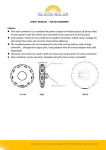
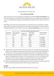
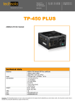
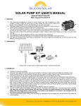
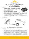
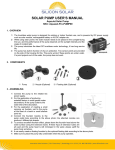
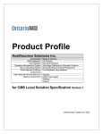
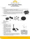
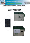
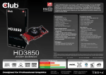
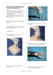
TruPower-Portable-500W Solar Starter kit This Solar starter kit is an easy to use solar power supply system that is the complete solution for all your solar power needs. It is a “solar generator” that converts nature’s sun light into electricity, and can be used as a power source to run your household appliances, such as energy saving lamp, laptop computer, radio, DVD, TV, electric fan, satellite receiver…. (Total power output of the appliances should be less than 500 watt) This solar power supply system is grid independent, and is useful for places that either have problems with electricity supply, or the utility grid is difficult to access. This product is so designed that you are able to expand it to a bigger solar system should you have intention to power more household appliances with solar. Simply connect TruPower-Portable-90A solar add on kit to this product through a TruPower-Portable-Extender. How do a solar power kit work? Solar panel(s) convert sunlight into DC electricity, and electricity is then sent to the battery. The battery acts as a storage device, so that power is available even when there is no sunlight. The battery also acts as a power stabilizer, since electricity from solar panel varies according to the strength of the sunlight. The inverter draws power from the battery and converts the electricity from 12VDC to 220/110VAC, so that use with AC household appliances is possible. The charge regulator is connected between the solar panel(s) and battery, to control the charge and/or discharge process, so that the battery always works within a proper range. Power Generation Unit Solar panel Control Unit Charge Regulator Power Application Unit Inverter Power Storage Unit Rechargeable Battery AC Output DC Output The solar system generates electricity in proportion to the amount of sunlight exposed to the solar panel(s). The peak generation of power is on a clear day when the sun is at a normal angle to the solar panel(s). Clouds, seasonal variation of solar angle, dust/dirt on solar panel, off-azimuth orientation, and any incidental shading could decrease the performance of solar panel. Power loss during transmission through the lead wire and connector, and efficiency of charge controller and inverter will also decrease the amount of electricity. Caution Before using, carefully read and understand the instruction user’s manual. Charge regulator + inverter + LED light tube are not waterproof. Please use them in a sheltered, dry and well ventilated place This product does not include a battery. Please use 12V battery only, battery capacity of 40Ah Innovative Solar Solutions | 2917 State Hwy 7, Bainbridge, N.Y. 13733 | Ph: 800.786.0329 | www.SiliconSolar.com minimum is recommended. Total power output of the household appliances that connect to this product should not exceed 500Watt. For continuous operation, please do not exceed 450Watt. Clean the surface of solar panel periodically with a soft cloth for its best performance. Do not reverse the polarity of the load, the solar panel, & the battery. Please do not touch any bare stripped lead wire to prevent electric shock Please turn off your application before connecting to this product This appliance is not intended for use by young children or infirm person unless they are being adequately supervised by a responsible person to ensure that they can use the application safely. Part List Serial Description of parts Quantity Mono-crystalline solar panel 1 Peak Power Output: 90Wp@18V (±5%) Anodized aluminum alloy frame with 6ft connect wire. 1 PC 2 Mounting assembly 2 PCs 3 Mounting screws with nuts 10 PCs 4 5 For securing solar panel and assembly Extension wire 12 feet long 1 PC Tinned wire 1 PC 1 foot, Cross section: 12 feet Battery connecting wire 6 6 feet long 2 PCs Innovative Solar Solutions | 2917 State Hwy 7, Bainbridge, N.Y. 13733 | Ph: 800.786.0329 | www.SiliconSolar.com 2-in-1 output lead wire on charge regulator 7 1 foot long 2X DC socket for LED light tubs Cigar lighter socket for other applications 1 PC LED Light tube 8 15 feet lead wire. 24 Super bright LEDs On/Off switch 2 PCs Solar Charge regulator 12V / 30A Max 9 10 1 PC Inverter 12VDC to 230VAC, 500W Max 1 PC Operation Solar panel The solar panel should be mounted at a position that can have direct contact with sunlight, by facing the solar cell to the sun. Make sure that no shadow is cast onto the solar panel to ensure better power output. Solar panel comes with 6 feet lead wire, fit it with tinned wire (No. 5 in the part list) which allows the solar panel to be connected to the charge regulator. Extension wire (No. 4 in the part list) is provided just in case the lead wire from solar panel is not long enough. Use the extension wire only when needed. Fit it in between the solar panel lead wire and the tinned wire. Mounting assembly Mounting assembly consist of two triangle mounts. Open the triangle mount, and adjust it to the desire angle. Recommend angle that is close to your local latitude (Please refer to below chart for reference). Then secure the angle with nut and screw. Please refer to “Secure angle” Secure the two triangle mounts onto the solar panel. There are two install holes on each long frame of the solar panel, please secure the triangle mounts onto the solar panel to all four holes with screws and nuts. Please refer to “Secure solar panel onto mounting assembly”. The mounting assembly can be secured to the ground or other surface through the two ground mount holes on each of the triangle mounts (long side). Innovative Solar Solutions | 2917 State Hwy 7, Bainbridge, N.Y. 13733 | Ph: 800.786.0329 | www.SiliconSolar.com Secure solar panel onto mounting assembly Secure angle On the Roof Angle o o 45 o 60 o o 45 o 30 On the Ground Southern USA (California) Australia, Southern Europe (Italy, Greece) Chile (Santiago) Northern USA (New York), Canada. Europe (France, Germany, Spain) 30 70 Applicable Area o 60-70 Northern Europe:(Sweden) Russia (Moscow) On the wall Innovative Solar Solutions | 2917 State Hwy 7, Bainbridge, N.Y. 13733 | Ph: 800.786.0329 | www.SiliconSolar.com Charge regulator Load on/off switch Display Shift Button DC Load - DC Load + Battery - Battery + Solar panel- Solar panel + Main feature * Solar Charge Regulator is able to handle charge and discharge from 12V battery * It provides over-charging, over-discharging, and over-load protection. Therefore keep the whole solar system at proper working condition. * This solar charge regulator uses the latest Microcomputer-chip to realize intelligence control. * PWM (pulse width modulation) charging circuit is used for higher efficiency. * Big LCD display available for easy monitoring. Caution: * This solar charge regulator handles 12V batteries only. * This solar charge regulator handle maximum solar input of 30A, please do not exceed this limit. * The charge regulator is not waterproof. Please use them in a sheltered, dry and well ventilated place. How to connect * Battery should be connected to the port where it shows . . Please note that “+” stand for positive pole, and “-” stands for negative pole. Make sure you connect with polarity. * DC load should be connected to the port where it shows In the case of this product; you can also choose to connect lead wire #7 as stated in the part list to these two ports. Please note that “+” stand for positive pole, and “-” stands for negative pole. Make sure you connect with polarity. Innovative Solar Solutions | 2917 State Hwy 7, Bainbridge, N.Y. 13733 | Ph: 800.786.0329 | www.SiliconSolar.com * Solar panel should be connected to the port where it shows Please note that “+” stand for positive pole, and “-” stands for negative pole. Make sure you connect with polarity. * Please make sure that all the connection is secure and correct. * Do not short circuit when connecting the battery, fail to do so may cause sparking or explosion. * When connecting and disconnect from the solar charge regulator, please always follow the sequence as stated below. Connecting: Battery Solar Panel Load Disconnecting: Solar panel Turn off your appliance and the “load on/off” switch on solar charge regulator load battery How to monitor * The big LCD display helps you to monitor the working status of this solar power kit. The Display Shift Button works in a cycle pattern. By pressing the bottom, LCD will switch in between the three different models as below. Battery voltage Model 1 Output current to load Model 2 Solar charge current Model 3 Innovative Solar Solutions | 2917 State Hwy 7, Bainbridge, N.Y. 13733 | Ph: 800.786.0329 | www.SiliconSolar.com Display Shift Button ▲ Model 1 Load on/off switch When you press ▲, LCD screen When you press at the bottom of this model, it will shows the working voltage of the not change what is being display on the LCD 2 battery When you press ▲ for the second time, the LCD Screen shows the output current from battery to load. Press at the bottom of this model: 1. When the load output is under ON status, LCD will show output current from battery to load. 2. When the load output is under OFF status, LCD will show 00.0A. 3. If over-discharge protection is activated, the load output will be cut off. If you press at the bottom under it will becomes invalid and have a buzzer alarm. 4. If system recovers from over-discharge or over load protection, please press at the bottom twice to reactivate the load output function. 3 when you press ▲ for the third When you press time, the LCD Screen shows the not change what is being display on the LCD. at the bottom of this model, it will charging current from the solar panel to the battery Inverter Please connect the alligator battery clamps coming from the inverter to battery. Please note that “+” and red color stand for positive pole, and “-” and black color stands for negative pole. Make sure you connect with correct polarity. For more details please refer to inverter user manual. Caution * Do not short circuit when connecting the battery, fail to do so may cause sparking or explosion * Total power output of the household appliances that connect to this product should not exceed 500 Watt. For continuous operation, please do not exceed 450Watt Innovative Solar Solutions | 2917 State Hwy 7, Bainbridge, N.Y. 13733 | Ph: 800.786.0329 | www.SiliconSolar.com Solar Starter Kit connection diagram Please refer to corresponding serial number in the part list 1 2 4 Use extension wire only when needed Connect to load 9 5 Connect to Battery Connect to Solar panel 7 6 8 Battery NOT included 10 Saddle battery clamp from charge regulator Alligator battery clamp from Inverter Innovative Solar Solutions | 2917 State Hwy 7, Bainbridge, N.Y. 13733 | Ph: 800.786.0329 | www.SiliconSolar.com How to expand your solar kit A TruPower-Portable-Extender is needed to expand your solar kit. Combine the solar starter kit and the solar add on kit(s), by plugging the lead wire coming from the solar panel (or the extension wire, if it is used) to one of the inputs of the solar combiner. Plug one end of the tinned wire to the output port of the solar combiner, and the other end to the charge regulator. You can add multiple units of Solar Add On (TruPower-Portable-90A) onto the solar combiner, but make sure that total power output of solar panels from all the Add on kits + starter kit do not exceeds 510Watt. Failure to do so will result in damage to the product. If multiple units of solar kits are combined, bigger battery capacity will be required to hold the increased amount of solar power. For minimum battery capacity requirement, please refer to the chart in page 1 in the user’s manual of Solar Add On Kit (TruPower-Portable-90A). You can either change to a bigger capacity 12V battery, or connect additional battery with the same capacity to the original one. There are two pieces of battery connecting wire included in the solar start kit, use the additional wire to join the two batteries. Connection diagram Solar Add On Kit (SoloPower-Portable-90A) Solar Extender NOT included Batteries NOT included TruPower-Portable-500W Innovative Solar Solutions | 2917 State Hwy 7, Bainbridge, N.Y. 13733 | Ph: 800.786.0329 | www.SiliconSolar.com