1
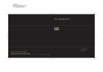
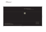
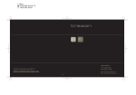
Dot XL-3
INSTALLATION GUIDE
V0.7
Cover:
Dot XL-3
Dot XL-3 Diffuser Version
CONTENT
1. INTRODUCTION
3
2. installation
6
3. Safety And Operation
14
4. SYSTEM CONFIGURATION
15
5. Care and Maintenance
17
6. TECHNICAL SPECIFICATION
18
7. Troubleshooting
19
8. Warranty Statement
19
www.traxontechnologies.com
©2015 traxon technologies - AN OSRAM Business. all rights reserved. traxon™, tx connect ® , are trademarks of traxon technologies. u.s. patents, e.u.
patents, japan patents, other patents pending. specifications are subject to change without notice.
Installation Guide
06/15 V0.7
2 of 20
1. INTRODUCTION
1.1 General
The Traxon™ Dot XL-3 is an extra bright dot with 3 LEDs per dot casing. The dots are
constructed on a flexible cable with a customizable pitch containing up to 88 dots. With
numerous additional customization options, the Dot XL’s flexibility is unparalleled and its
application possibilities nearly limitless. The dots are single dot controllable by DMX512 or
e:pix (DVI capable) making this durable, scalable solution equally ideal for vivid accent, text,
and graphics in installations of any size and complexity. Each string is connected via the Dot
XL Pixel Distributor which can be easily daisy chained to form large installations.
The IP67-rated, UV-resistant cover and thermoplastic casing make the Dot XL suitable for a
variety of outdoor applications.
Features:
• Up to 88 dots on a string for Dot XL-3 (dependant on length of lead cable and pixel pitch)
• DMX512 / e:pix Control
• Daisy Chain System
• Auto-Addressing
• SMART CHIP™ Technology
• Outdoor Applications (Dot XL IP66/IP67; Pixel Distributor IP66; LED Engine IP67)
• Suitable for irregular surfaces, planes, and configurations
• Optional field-cut end cap for cable
• Optional Diffuser Dome available
www.traxontechnologies.com
©2015 traxon technologies - AN OSRAM Business. all rights reserved. traxon™, tx connect ® , are trademarks of traxon technologies. u.s. patents, e.u.
patents, japan patents, other patents pending. specifications are subject to change without notice.
Installation Guide
06/15 V0.7
3 of 20
1.2 Dimensions
FIG.1: Dot XL-3
Ø20mm/0.79”
4.1mm/0.16”
16.5mm/0.65”
4.1mm/0.16”
WITH OPTIONAL
DIFFUSER DOME
IN CLIP ASSEMBLY
WITH OPTIONAL
CLIP ASSEMBLY
3.3mm/0.13”
62.5mm/2.46”
27mm/1.06”
23mm/0.91”
15.5mm/0.61”
62.5mm/2.46”
11.8mm/0.46”
60mm/2.36”
36.2mm/1.43”
16.50mm/0.65”
9”
0.7
m/
0m
Ø2
36.20mm/1.43
FIG.2: Dot XL-3 String
60mm/2.36”
265mm/10.4”
3.30mm/0.13”
150mm/5.9”
11.80mm/0.467”
10000mm/393.7”
Optional clip
Optional clip with
diffuser dome
www.traxontechnologies.com
©2015 traxon technologies - AN OSRAM Business. all rights reserved. traxon™, tx connect ® , are trademarks of traxon technologies. u.s. patents, e.u.
patents, japan patents, other patents pending. specifications are subject to change without notice.
Installation Guide
06/15 V0.7
4 of 20
1.3 Pixel Distributor
FIG.3: Pixel Distributor
Cable length: 1000mm/39.4”
198mm/7.8”
68mm/2.7”
20mm/0.79”
Pixel
Distributor
204mm/8”
Ø6.3mm/0.25” x 4
9mm/0.35”
89mm/3.5”
50mm/2”
LED Engine
Cable length:
300mm/11.8”
222mm/8.7”
M4 x 4
1.4 Packing Contents
FIG.4: Packing Contents
1 x Pixel Distributor
4 x Screws PSU Mounting
Dot XL String
www.traxontechnologies.com
©2015 traxon technologies - AN OSRAM Business. all rights reserved. traxon™, tx connect ® , are trademarks of traxon technologies. u.s. patents, e.u.
patents, japan patents, other patents pending. specifications are subject to change without notice.
Installation Guide
06/15 V0.7
5 of 20
2. installation
2.1 Points To Consider
Plan your installation before mounting any luminaires. The following should be considered for
a successful installation.
• Weather conditions and ambient temperature of installation site.
• Appropriate cable lengths and the use of optional Field-cut End caps.
• Adequate space for better heat dissipation (150mm apart) of LED Engines (see 2.3 On-Site
Installation step 1).
• Appropriate length of DIN rail and number of anchor bolts to secure DIN rail to installation
surface.
• The number of Dot XLs and appropriate Pixel Distributors with LED Engines.
• DMX512 controller to be used to control the Dot XLs.
2.2 Pre-Installation Checks
2.2.1 Installation Checklist
1. Prepare cables and all necessary accessories.
2. Perform functional check of Dot XLs.
3. Ensure the DATA OUT connector on all Pixel Distributors are covered by the Waterproof
End Cap after testing (see FIG 5). Keep Waterproof End Caps safe for reuse.
4. Ensure all pre-installation checks laid out below have been followed.
5. Mount the Dot XLs on-site. If the installation is to be left uncompleted overnight, place all
non-connected LED Engines, Pixel Distributors and Dot XLs in an indoor environment.
Ensure all the Connection Cables, Dot XLs with LED Engines and Pixel Distributors are initially
stored in a dry area to guarantee the complete sealing of the system from water before
installation.
www.traxontechnologies.com
©2015 traxon technologies - AN OSRAM Business. all rights reserved. traxon™, tx connect ® , are trademarks of traxon technologies. u.s. patents, e.u.
patents, japan patents, other patents pending. specifications are subject to change without notice.
Installation Guide
06/15 V0.7
6 of 20
Connector should be properly connected with cable connectors and the DATA OUT of the
last Pixel Distributor should be covered by its Waterproof End Cap to ensure IP66/67 rating.
FIG.5: Seal last Pixel Distributor with Waterproof End Cap
Tightening Torque
0.49~0.69Nm (5~7kgfcm)
Waterproof End Cap
2.2.2 Handling The Dot XL String
When transporting or preparing the Dot XL string, please handle with care. To reduce stress
on cables, carry by the dots and not the cable during transit.
Allow slack on cable to
FIG.6: Correct way of handling
reduce stress Dot XL String
Allow slack on cable to
reduce stress
www.traxontechnologies.com
©2015 traxon technologies - AN OSRAM Business. all rights reserved. traxon™, tx connect ® , are trademarks of traxon technologies. u.s. patents, e.u.
patents, japan patents, other patents pending. specifications are subject to change without notice.
Installation Guide
06/15 V0.7
7 of 20
2.2.3 Requirements Of Cable Bending And Twisting
Please take EXTRA precautions before bending or twisting Dot XL cable.
Round Lead Cable must NOT be bent below the Minimum Bending Radius (4x Cable
Diameter) and the Non-Bendable Length of 50mm near the connector end or near the cable
overmold MUST be adhered to.
FIG.7: Minimum Cable Bending and Non-Bendable Length Requirement
D
Ø9.5mm/0.37”
D
≥4
(Minimum Bending Radius)
38mm/1.50”
50mm/1.97”
(Non-Bendable Length)
The flat Dot XL Cable must NOT be bent/twisted below 20mm (0.79”) from edge of Dot
housing (Non-Bendable/Non-Twistable Length).
Twisting the flat cable is NOT recommended. If twisting is necessary for installation, please
adhere to the above Non-Twistable Length and ensure the mounting pitch is greater than or
equal to 75% of the normal Dot to Dot pitch. The middle part of the cable must be secured to
the mounting fixture with a cable tie (see 2.3 On-Site Installation steps 6-7 and FIGs 12-13).
Ensure no damage is generated on the cable.
FIG.8: Minimum Clearance
Minimum clearance
from dot
20mm/0.79”
Non-Bendable/Non-Twistable
Length
NOTE: Water ingress incurred due to excess cable bending/twisting will not be under
warranty by Traxon Technologies.
www.traxontechnologies.com
©2015 traxon technologies - AN OSRAM Business. all rights reserved. traxon™, tx connect ® , are trademarks of traxon technologies. u.s. patents, e.u.
patents, japan patents, other patents pending. specifications are subject to change without notice.
Installation Guide
06/15 V0.7
8 of 20
2.2.4 Optional Field-Cut End Cap
To prematurely end the length of a string of Dots, the optional Field-Cut End Cap should be
used with silicone applied on open-ended cable. This should be done at least one (1) day
before on-site installation to allow curing of silicone.
FIG.9: Field-Cut Sealing Procedures
R
LI TV
CO
NE
SI
Minimum clearance
from last node
35mm/1.38”
R
LI TV
CO
NE
SI
Terminate cable with a
straight cut. Ensure there
is enough clearance to
work with. Clean the
surface using alcohol.
1
2
Apply RTV silicone (not
included) on open-ended
cable.
R
LI TV
CO
N
RE
LI TV
CO
NE
SI
R
LI TV
CO
NE
SI
SI
R
LI TV
CO
NE
SI
3
4
Fill end cap cavity with
RTV silicone and press
open cable end inside.
Cover parts with RTV
silicone and close
cover.
(DO.AC.0003600)
5 Clean excess
6
silicone from end
cap.
Place on flat surface and put
pressure on end cap (eg. with
a weighted object) for the cure
time recommended by RTV
silicone’s instructions.
www.traxontechnologies.com
©2015 traxon technologies - AN OSRAM Business. all rights reserved. traxon™, tx connect ® , are trademarks of traxon technologies. u.s. patents, e.u.
patents, japan patents, other patents pending. specifications are subject to change without notice.
Installation Guide
06/15 V0.7
9 of 20
2.2.5 Installation Sequence
1. Plan for any possible bending of cables (refer to Section 2.2.3 Requirements Of Cable
Bending And Twisting).
2. Always keep the Waterproof End Cap on the Pixel Distributors or keep them safe in a
container for reuse.
3. Connect Dot XLs with LED Engines and Pixel Distributors in the daisy-chain manner
outlined in the System Diagram to form large installations.
4. Perform functional check on all Dot XLs and inspect cables for any damage. Check for
any abnormalities with the signal.
5. Report any functional defect found to your nearest Traxon Technologies office. DO NOT
attempt to install Dot XLs with functional defects on-site.
www.traxontechnologies.com
©2015 traxon technologies - AN OSRAM Business. all rights reserved. traxon™, tx connect ® , are trademarks of traxon technologies. u.s. patents, e.u.
patents, japan patents, other patents pending. specifications are subject to change without notice.
Installation Guide
06/15 V0.7
10 of 20
2.3 On-Site Installation
• DO NOT attempt installation in wet or severe weather conditions.
• DO NOT leave and expose any Dot XL, Pixel Distributor or LED Engine
unconnected under wet/raining or snowing environment.
• Ensure all the cable connectors of Dot XLs are removed from the Pixel
Distributors before installing.
• DO NOT pull on cable of Dot XLs. IP failure induced by stressed/damaged
cables during or after installation will not be under warranty by Traxon
Technologies.
• ALWAYS keep the cables protected from sharp objects and ensure no
damage is generated on the cable.
• Failure to keep Dot XLs within the operating temperature range of –20°C
to 50°C (–4°F to 122°F) and storage temperature range of –20°C to 70°C
(–4°F to 158°F) will void the product’s warranty.
1. Fix LED Engine atop Pixel Distributor with included M4 screws.
NOTE: Keep adjacent LED Engines and Pixel Distributors a minimum 150mm (5.91”)
apart for better heat dissipation.
FIG.10: Mounting LED Engine atop Pixel Distributor
LED Engine mounts
on top of the Pixel Distributor
M4 screws
≥150mm/5.91”
clearance
(Included)
(LED Engine is ordered separately)
≥150mm/5.91”
clearance
Mount Pixel Distributor
with connectors facing down
≥150mm/5.91”
clearance
M6 anchor bolts
(Not included)
≥150mm/5.91”
clearance
≥150mm/5.91”
clearance
≥150mm/5.91”
clearance
2. Mount the Pixel Distributor with 4x M6 Anchor Bolts (not included). Recommended
orientation is with connectors facing DOWN (see above diagram).
3. Dot XLs must be mounted without any stress induced at the boundary area of the cable
and Dot.
www.traxontechnologies.com
©2015 traxon technologies - AN OSRAM Business. all rights reserved. traxon™, tx connect ® , are trademarks of traxon technologies. u.s. patents, e.u.
patents, japan patents, other patents pending. specifications are subject to change without notice.
Installation Guide
06/15 V0.7
11 of 20
4. Dot XLs MUST be mounted to the installation surface with dot clips and DIN rail.
FIG.11: Mounting the Dot XLs
15mm DIN rail
Option 1. Screw mounting
the dot clip.
Dot XL-3
Diffuser dome
Dot Clip - back
Dot Clip - front
Without diffuser dome
Option 2. Dot clip snaps onto DIN rail.
5. Cable segment must not be bent below 20mm from the housing of the Dot XLs and
cable overmold (Minimum Bending Length).
6. Secure the cables between Dot XLs (approximately halfway, using cable tie) and create a
small clearance beneath the cable (see below diagram). Ensure no damage is generated
on the cable.
FIG.12: Securing the cable
Observe clearance
Cable tie
DIN rail
www.traxontechnologies.com
©2015 traxon technologies - AN OSRAM Business. all rights reserved. traxon™, tx connect ® , are trademarks of traxon technologies. u.s. patents, e.u.
patents, japan patents, other patents pending. specifications are subject to change without notice.
Installation Guide
06/15 V0.7
12 of 20
7. If the cable between Dot XLs requires twisting due to a change in mounting direction,
ensure the mounting pitch after-twisting is more than or equal to 75% of the normal Dot
to Dot pitch.
FIG.13: Twisting requirements
Non-Twistable Length
20mm/0.79”
Secure center of
cable with cable tie
≥75% L
L = Length of cable
Non-Twistable Length
20mm/0.79”
Secure center of
cable with cable tie
L = Length of cable
≥75% L
Non-Twistable Length
www.traxontechnologies.com
©2015 traxon technologies - AN OSRAM Business. all rights reserved. traxon™, tx connect ® , are trademarks of traxon technologies. u.s. patents, e.u.
patents, japan patents, other patents pending. specifications are subject to change without notice.
Installation Guide
06/15 V0.7
13 of 20
3. Safety And Operation
1. CAUTION - Unplug the power supply from the mains power before connecting any
cables as this can damage the products.
2. CAUTION - Avoid looking directly into the LED light source at close range for your own
safety.
3. Persons installing this product should make sure:
1. The installation complies with all applicable codes, state and local laws,
ordinances, standards and safety regulations.
2. The installation environment is carefully studied and suitable surge protection
measure(s) is taken.
3. He or she is qualified for the handling of electrical equipment.
4. Do not attempt to install or use the product until installation instructions and safety labels
are fully understood. This product is designed for indoor and outdoor use.
5. Ensure product operates within the specified temperature range. (Refer to 6. TECHNICAL
SPECIFICATION for more details.)
6. Do not attempt to open the product. Not user serviceable.
7. Do not use the product if any part of it, or the power cables are damaged.
8. Only use product for specified voltage, do not exceed. (Refer to 6. TECHNICAL
SPECIFICATION for more details.)
9. Always maintain connection to ensure waterproofing.
10. If the product has been subjected to drastic temperature variances, for example,
following transportation, do not connect the fixture until it has reached room temperature,
as moisture condensation may cause electric shock and product damages.
11. When installing the products and system power supplies, please ensure they will not
be exposed to moisture and extreme heat (and direct sunlight for outdoor products).
Besides, keep a clean operating environment for the fixtures and system power supplies.
12. Please study this Installation Guide thoroughly and check the latest Technical
Specification Sheets available from the Traxon website www.traxontechnologies.com
before setup.
13. Any non-compliance of the Installation Guide will void the Traxon warranty.
www.traxontechnologies.com
©2015 traxon technologies - AN OSRAM Business. all rights reserved. traxon™, tx connect ® , are trademarks of traxon technologies. u.s. patents, e.u.
patents, japan patents, other patents pending. specifications are subject to change without notice.
Installation Guide
06/15 V0.7
14 of 20
Installation Guide
512 DMX Channels per output
CONTROLLER
Butler S2
Butler S2
INDOOR
Maximum: 100m
To other distributor chain
TX Connect Data
Indoor/Outdoor Bridge Cable (5m/16.4ft)
RJ45 Male Connector Housing IP67
To construct a longer Data Bridge Cable,
use Indoor Data Cable and Outdoor
RJ45 Housing.
OUTDOOR
LED Engine 75W 15V Outdoor
06/15 V0.7
Last dot of string
First dot of string
TX Connect Data Outdoor Cable
0.3m/1ft or 3m/10ft available
300mm
Installation engineer should use
appropriate plugs for outdoor connection.
AC 110V/220V 50/60Hz
1000mm
Dot pitch: 100mm
minimum
1PXL dots
3 channels per dot
For standard 48-Dot XL-3 with 150mm pitch,
max. lead cable length is 10m.
Flat cable lead cable:
Maximum lead cable length depends
on the number of dots and the dot pitch.
Round lead cable: 300mm
Dot XL Pixel Distributor
Maximum number of Pixel Distributors in the
daisy chain depends on available DMX and e:pix channels.
End cap
4. SYSTEM CONFIGURATION
FIG.14: System Diagram – Butler S2
www.traxontechnologies.com
©2015 traxon technologies - AN OSRAM Business. all rights reserved. traxon™, tx connect ® , are trademarks of traxon technologies. u.s. patents, e.u.
patents, japan patents, other patents pending. specifications are subject to change without notice.
15 of 20
Installation Guide
DVI
Source
Ethernet Switch
LCE2 fx
06/15 V0.7
DVI OUT
DVI IN
DVI OUT
DVI IN
OUTDOOR
Each output: 1536 channels.
Total on 8 outputs: 12288 channels.
Maximum 8 outputs.
Maximum: 100m
TX Connect Data
Indoor/Outdoor Bridge Cable (5m/16.4ft)
RJ45 Male Connector Housing IP67
SEE VMC SPECIFICATION FOR MORE INFORMATION
USE DVI SPLITTER FOR FURTHER VMC CHAINS
Last dot of string
First dot of string
TX Connect Data Outdoor Cable
0.3m/1ft and 3m/10ft available
300mm
Installation engineer should use
appropriate plugs for outdoor connection.
AC 110V/220V 50/60Hz
LED Engine 75W 15V Outdoor
To construct a longer Data Bridge Cable,
use Indoor Data Cable and Outdoor
RJ45 Housing.
DAISY-CHAINED VMCs
MAX. UNITS PER CHAIN: 8
Video Micro Converter (VMC)
Ethernet
Source
INDOOR
1000mm
Dot pitch: 100mm
minimum
1PXL dots
3 channels per dot
For standard 48-Dot XL-3 with 150mm pitch,
max. lead cable length is 10m.
Flat cable lead cable:
Maximum lead cable length depends
on the number of dots and the dot pitch.
Round lead cable: 300mm
Dot XL Pixel Distributor
Maximum number of Pixel Distributors in the
daisy chain depends on available DMX and e:pix channels.
End cap
FIG.15: System Diagram – Video Micro Converter
www.traxontechnologies.com
©2015 traxon technologies - AN OSRAM Business. all rights reserved. traxon™, tx connect ® , are trademarks of traxon technologies. u.s. patents, e.u.
patents, japan patents, other patents pending. specifications are subject to change without notice.
16 of 20
5. Care and Maintenance
Traxon™ products are of superior design and quality and should be treated with care. The
recommendations below will help fulfill any warranty obligations and gain good use and
longevity from the products.
• Do not attempt or use the product(s) until you read and understand the installation
instructions. Failure to adhere to these instructions could result in serious injury or property
damage.
• Do not use product(s) if cables are damaged.
• Do not connect cables and connectors when wet or in wet area. Moisture on bare
connectors can cause electric shock and damage to product(s).
• Do not use product(s) in extreme heat environment. Ensure there is sufficient airflow and
use cool air circulation if required.
• Do not drop, knock, or shake product(s). Rough handling can damage the electronics and
void the warranty.
• Do not use harsh chemicals, cleaning solvents, or strong detergents to clean products.
Wipe with a damp cloth on housings and a dry cloth on electronics to remove dirt or dust.
• Do not attempt to service or repair the product(s) unless done by an authorized service
personnel. Contact your local Traxon office or distributor for details.
• If the product is not working as specified, please contact your nearest authorized service
center or Traxon Technologies office for assistance.
www.traxontechnologies.com
©2015 traxon technologies - AN OSRAM Business. all rights reserved. traxon™, tx connect ® , are trademarks of traxon technologies. u.s. patents, e.u.
patents, japan patents, other patents pending. specifications are subject to change without notice.
Installation Guide
06/15 V0.7
17 of 20
6. TECHNICAL SPECIFICATION
Dot XL-3
Color Range:
16.7 million additive RGB colors with variable intensity
Light Source:
3 High intensity Nichia SMD LEDs per dot
Beam Angle:
120° (clear cover)
Power Input:
15V DC
Power Consumption (per
dot):
1.5W max.
Weight:
25g (Dot); 670g (Pixel Distributor)
Operating Temperature:
–20°C to 50°C / –4°F to 122°F
Storage Temperature:
–20°C to 70°C / –4°F to 158°F
As with all electronic devices, LED output degrades over time - a term called lumen
depreciation. This also explains why it is nearly impossible to expect photometric
performances of two LED products with different service life spans to be the same. The
rate of LED degradation is a complex function of many factors such as operating efficiency,
duration of continuous operation, and operating conditions (e.g. ambient temperature).
Because LEDs are semiconductor devices, their performances are subject to inherent
variability commonly found in semiconductor industry. To improve consistency in performance
across the same product, LED manufacturers “sort” LEDs into bins according to different
preset parameters, such as forward driving voltage, illumination, etc. Whereas binning is a
sorting function, it is not a correction process. Inherent variability in the manufacturing process
always results in different binning distributions according to different production lots. Traxon
uses automatically binned LEDs on its products, thereby minimizing output variations within
the model range.
www.traxontechnologies.com
©2015 traxon technologies - AN OSRAM Business. all rights reserved. traxon™, tx connect ® , are trademarks of traxon technologies. u.s. patents, e.u.
patents, japan patents, other patents pending. specifications are subject to change without notice.
Installation Guide
06/15 V0.7
18 of 20
7. Troubleshooting
CAUTION: Ensure power supply is OFF when disconnecting / connecting
cables.
Problem
Cause
Product does
NOT light up
after installation
Incorrect power
connection
Possible Solutions
• Check Mains Power
• Check power supply leads and wire
connections
• Ensure output wires are connected with
proper polarity
Shadowing
Light source covered
• Adjust pitch between Dot XL strings
• Check for cables, wires or unwanted
Modules are
dim
Excess products
connected
• Ensure the power supplies are not
Flickering
Incorrect power input/
Excess products
connected
• Ensure the input voltage is correct
• Ensure the power supplies are not
debris covering LED light source
overloaded due to an excess of products
connected
overloaded due to an excess of products
connected
If problems persist or the product is not working as specified, please contact your nearest
authorized service center or Traxon Technologies office for assistance.
8. Warranty Statement
Traxon Technologies warrants its Products against material or workmanship defects for a
period of three (3) years from date of purchase, provided that the purchased items are used
under the conditions stated in this user manual.
Please refer www.traxontechnologies.com for all warranty terms and conditions.
www.traxontechnologies.com
©2015 traxon technologies - AN OSRAM Business. all rights reserved. traxon™, tx connect ® , are trademarks of traxon technologies. u.s. patents, e.u.
patents, japan patents, other patents pending. specifications are subject to change without notice.
Installation Guide
06/15 V0.7
19 of 20
Please check for the latest updates and changes on the Traxon website.
© 2015 TRAXON TECHNOLOGIES ALL RIGHT RESERVED. Information is subject to change without prior notice.
www.traxontechnologies.com