1
US 20040061616A1
(19) United States
(12) Patent Application Publication (10) Pub. N0.2 US 2004/0061616 A1
(43) Pub. Date:
Fischer et al.
(54) OUTAGE NOTIFICATION DEVICE AND
Apr. 1, 2004
Publication Classi?cation
METHOD
(76) Inventors: Roger L. Fischer, Dallas, TX (US);
Russell B. Schultz, Colcord, OK (US)
(51)
Int. Cl? ................................................... ..G08B 21/00
(52)
Us. 01. .......................................... .. 340/657; 340/531
(57)
Correspondence Address:
An outage noti?cation system for detecting a poWer outage
Robert J. Ward
Hunton & Williams LLP
at a customer location is provided. The outage noti?cation
system comprises a ?rst outage noti?cation device operably
Energy Plaza, 30th Floor
1601 Bryan Street
Dallas, TX 75201-3402 (US)
(21) Appl. No.:
10/676,655
(22) Filed:
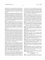
Sep. 26, 2003
ABSTRACT
coupled to a ?rst circuit at the customer location, a second
device operably coupled to a second circuit at the customer
location. The ?rst device is operable to determine a status of
poWer supply to the ?rst circuit and communicate the status
of poWer supply to the ?rst circuit to the second device. The
second device is operable to determine a status of poWer
Related US. Application Data
supply to the second circuit (or other desired parameter in an
alternative embodiment) and notify, via a network, a receiv
ing system associated With the electric utility of a poWer
(60) Provisional application No. 60/415,070, ?led on Sep.
30, 2002.
outage at the customer location based at least in part on the
statuses of poWer supply to the ?rst and/or second circuits.
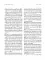
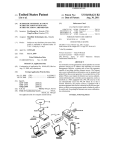
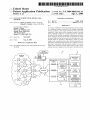
OUTAGE
15
MESSAGE
TRAFFIC
10
NOTIFICATION
2
/
IVR
SYSTEM
BACK OFFICE
SYSTEMS
P1
12/
12
14
MODEM DATA
sERvER
DATABASE
.
3-PHASE
P1
0“
MESSAGE/
14
12
P1
NOTIFICATION
DATA
USAGE
PROFILING
I
E
OUTBOUND
.
.
MESSAGE/
OTHER
DATA
ENERGY
23
12/ P1
18
APPLICATIONS
ENERGY MANAGER
APPLICATIONS
— DATA FLOW
- —- - DTMF
Patent Application Publication
Apr. 1, 2004 Sheet 2 0f 5
US 2004/0061616 A1
14
/
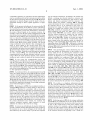
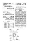
FIG. 2
31
/
_
,
35
DETECTOR
-———-
CONTROLLER
PRESS FOR TEST
30/
-
--—--
NOTiFlCATION
\
39
'
v
Q__
LINE
@
PHONE POWER
LLT’J'\3,(5
(E)
5
37
“a
(E)
38
14
(s
/
\
.V.50\
.
§
FIG. 3
V
2?
44
30/
_Z_
{FR
34
W
Q
32
33
v
\
r
42
48
.
O
40
Patent Application Publication
Apr. 1, 2004 Sheet 4 0f 5
US 2004/0061616 A1
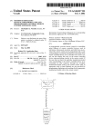
FIG. 5
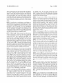
Accounl Home
@g
Device Name: Pei Slore
Localion Name: Bedford
Device ID: 100000000000040
Device Type: AFX
Device Version: 0
Service Level: Basic
Designaled Conlacls
Selecl a Primary Coniocl
Accouni Summary
Cuslo er Service
usingnlhis 5m
Admin Home Page
L099“!
v
f1028
Who should we'coniacf? Roger
@
How should we conlacl lhem? E-mail HZ f104a
Whal is lhe email address,
.
phone, fax, or pager number? Rogergemml‘com \106a
How long should we wail before
.
conlaciing? (0-99 minuies) 0
“TEA:
Who should we coniaci? Roger
Q
\102b
_\
How should we conlaci lhem? Phone
What is lhe email address,
_
104D
_
phone, fax, or pager number? 555 555 5555
How long should'we waif before
.
.
con i ac l lng ? ( 0-99 minu i es)
'
'
'
.
15
Mlnules
108D
'
_/102C
Who should we coniacl? Mary
9
How should we conlaci lhem? Fax
Whal is lhe email address,
1040
_
_
phone, fax, or pager number? 555 555 5550
How long should we wail before
106b
\106C
.
conlaciing? (0-99 minules) 35 (Tag:
l l Hll IIIQW
7/,
Patent Application Publication
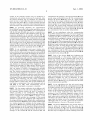
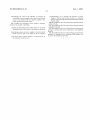
.110 112
\
Apr. 1, 2004 Sheet 5 0f 5
114a
116a
/
/
\
CALL
CALL
V1
P1
ELECTRIC
UTIUTY
CusT0IvIER
0
0
D
1
N
N
N
Y
1
I D
N
Y
1
1
Y
Y
FIG. 6
US 2004/0061616 A1
V
202\
/
PROVIDING AN ouTAGE
NOTIFICATION SYSTEM
I
204\ DETECTING THE STATUS OF POWER
SUPPLY ON A FIRsT CIRCUIT
PowER 0FF=1
i
POWER 0N=0
206\ DETECTING THE STATUS OF PowER
SUPPLY OF A sECoND CIRCUIT
ANALYZING THE STATUS OF
208/
POWER SUPPLY ON THE
FIRST AND SECOND CIRCuITs
NOTIFYING THE APPROPRIATE
210/
110 112 118
\
\
114D
116D
\
/
/
CALL
CusTDIvIER
V1
P1
P2
CALL
ELECTRIC
UTILITY
o
0
0
N
N
o '
0
' 1
N
Y
0
1
0
N
Y
0
1
1
N
Y
1
o
0
N
Y
1
o
1
N
Y
1
I
D
N
Y
I
1
1
Y
Y
"
F1G. 7
POWER 0FF=1
PowER 0N=0
CoNTACT BASED ON THE STATUS
OF PDwER SUPPLY DN THE FIRST
AND SECOND CIRCUITS
F168
-
Apr. 1, 2004
US 2004/0061616 A1
OUTAGE NOTIFICATION DEVICE AND METHOD
CROSS-REFERENCE TO RELATED
APPLICATIONS
[0001]
The present invention claims bene?t of Us. Pro
tem or device comprises a ?rst device operable to detect the
loss of poWer supply at a ?rst circuit of the customer
location, the ?rst device operable to communicate a status of
the ?rst device of poWer supply at the ?rst circuit as either
available or not available.
visional Application No. 60/415,070 ?led Sep. 30, 2002, the
entirety of Which is incorporated by reference herein for all
second device operable to detect the loss of poWer supply (or
purposes.
some other information) at a second circuit of the customer
FIELD OF THE INVENTION
[0002]
The present invention relates in general to the ?eld
of noti?cation and detection devices and more particularly,
but not by Way of limitation, to a poWer outage noti?cation
system and method to report information related to the loss
of poWer supply at a customer location.
BACKGROUND OF THE INVENTION
[0003]
When a customer of an electric utility suffers a
poWer outage, the customer typically must notify the electric
utility of the poWer outage. In the event that the poWer
outage occurs in the middle of the night or When the
customer is otherWise unable to detect the outage, the
residence or facility may go Without electricity for a con
siderable amount of time. In instances Where the continuous
supply of poWer is crucial to the customer, such as for
hospitals, manufacturing facilities and food storage facili
ties, this conventional outage noti?cation process can
severely affect the customer’s operations.
[0004] Accordingly, a number of complex and expensive
devices have been employed in the past to detect poWer
outages and report them to the electric utilities. Such devices
may implement a connection to the poWer supply at the
customer location coupled to the serial port of personal
computers dedicated for outage noti?cation. Once an outage
[0007]
The outage noti?cation device may also include a
location, the second device operable to communicate a
status of the second device of poWer supply (or other desired
information) at the second circuit as either available or not
available. The outage noti?cation device may also include a
microcontroller in communication With the ?rst and second
devices. The microcontroller operable to analyZe the status
of the ?rst and second devices of the poWer supply at the ?rst
and second circuits received by the ?rst and second devices
to determine Whether poWer supply may have been lost to
the facility or customer premises. The outage noti?cation
device may also include a netWork interface or communi
cation device operable to communicate With a receiving
system.
[0008] According to one embodiment of the present inven
tion, the communication device is operable to report on the
outage of poWer supply at the customer location to the
receiving system When the microcontroller determines that
poWer supply is lost at the ?rst and second circuits. Accord
ing to another embodiment of the present invention, the
communication device is operable to report on the outage of
poWer supply at the customer location to the receiving
system When the microcontroller determines that poWer
supply is unavailable at one of the ?rst or second circuits.
[0009] In other embodiments, the outage noti?cation sys
is detected at the serial port and a communication from the
tem may further include a dedicated communication link
betWeen the ?rst or second device and the microcontroller.
In this instance, the communication link may be a Wireless
personal computer has been received by the electric utility,
the electric utility may dispatch the appropriate technicians
communication link, While in other embodiments, the com
munication link may utiliZe telephone lines or poWer lines at
to re-establish poWer or repair the problem causing the
outage. Unfortunately, such systems suffer from severe
limitations With respect to ef?ciently and cost effectively
dealing With poWer outages at the customer location. To
illustrate, the use of such systems typically require the use
of a personal computer or Workstation, either of Which
generally are expensive to purchase and maintain. Further,
the customer location.
such systems typically notify the electric utility in the event
that poWer supply is lost on any circuit, resulting in Wasted
[0010]
In one embodiment, the outage noti?cation system
includes a third device operable to detect the loss of poWer
supply at a third circuit of the customer location, the third
device operable to communicate the status of the third
device of poWer supply at the third circuit. In this embodi
ment, the ?rst device and the communication device may be
integrated or contained Within a single housing. As such, the
?rst device may communicate With the communication
time and effort on the electric utility’s part When the cause
of the poWer outage to the circuit results from a local cause
at the customer location and not from a problem for Which
device in an integrated communication manner, While the
second and third devices communicate With the communi
the electric utility is responsible.
by utiliZing the telephone lines, poWer lines or other dedi
cated Wiring Within the customer location, according to
SUMMARY OF THE INVENTION
[0005] Thus, a need exists for an improved outage noti
?cation system, outage detection device and method that
overcomes the disadvantages of prior outage noti?cation
systems and provides a more useful and cost ef?cient outage
noti?cation system.
[0006]
Embodiments of the present invention overcome
one or more of the problems noted above, and realiZe one or
more additional advantages. The present invention provides
an outage noti?cation system for detecting outage of poWer
supply at a customer location. The outage noti?cation sys
cation device in a Wireless manner, in one embodiment, or
other embodiments.
[0011] According to yet another embodiment of the
present invention, the ?rst device may include an adaptor for
poWering the ?rst device by coupling to an electric poWer
outlet at the customer location. The ?rst device also having
a battery for poWering the ?rst device in the event of an
outage at the outlet at the customer location. In one embodi
ment the ?rst device may further include an indicator system
to indicate the status of the poWer supply of the ?rst circuit,
as Well as, the status of the ?rst device, such as the status of
a battery included With a ?rst device. The indicator, in one
Apr. 1, 2004
US 2004/0061616 A1
embodiment, may be a light, While in other embodiments the
indicator may be a speaker. The indicator or enunciator may
be a light, speaker or other device for indicating the status
of the circuit(s), the device(s) or its battery, and may utilize
an audible, such as recorded voice message, for such status
information.
[0012]
In one embodiment, the receiving system may be
an integrated voice response system (IVR) and the commu
nication device may be operable to communicate a dual-tone
multi-frequency (DTMF) signal to the receiving system to
communicate information regarding status of the ?rst and
second devices and the processor. In another embodiment,
the receiving system may be operable to notify the electric
utility or the customer of the customer location via e-mail,
or in other embodiments, via pager, fax, telephone, Whether
Wireless, cellular, or standard telephone system, utiliZing an
automated voice response system.
the second circuit to the communication device by the
second device. The method further includes analyZing the
status of the ?rst and second devices’ status of poWer supply
of the ?rst and second circuits, by the processor, to deter
mine Whether the outage is limited to only one of the ?rst
and second circuits, or Whether both the ?rst and second
circuits are Without poWer supply indicating a complete loss
of poWer supply at the customer location.
[0017] One advantage of the present invention is the
capability to intelligently detect and analyZe the status of
poWer supply at the customer location to discern betWeen a
loss of poWer on an individual circuit as opposed to loss of
poWer on all monitored circuits indicative of a complete loss
of poWer supply at the customer location. This alloWs for a
more ef?cient response by dispatching the electric utility
only When a complete outage has been detected or only
notifying the customer or oWner of the customer location
When only some of the circuits have lost poWer supply.
[0013] Such noti?cation may include the duration of the
outage and Whether both the ?rst and second circuits have
lost poWer supply or Whether only one of the circuits is
Without poWer. In one embodiment the poWer, including the
current, voltage, of each circuit may be monitored by the
rated in and constitute a part of this speci?cation, illustrate
various embodiments of the invention and, together With the
description, serve to explain the principles of the invention.
?rst and second devices, analyZed by the processor and
communicated to the receiving system, via the communica
tion device. In another embodiment, the noti?cation may
BRIEF DESCRIPTION OF THE DRAWINGS
[0019] The present invention can be understood more
include When the outage occurred, as Well as When poWer
Was restored.
[0014] In one embodiment the ?rst device and/or the
communication device may be provided With a real-time
clock such that When the communication device communi
cates With the receiving system, the communication device
receives the actual current time from the receiving system.
This alloWs the ?rst device to communicate the status of
[0018] The accompanying draWings, Which are incorpo
completely by reading the folloWing Detailed Description of
the Invention, in conjunction With the accompanying draW
ings, in Which:
[0020]
FIG. 1 is a block diagram illustrating an exemplary
outage noti?cation system in accordance With at least one
embodiment of the present invention.
[0021] FIG. 2 is a front vieW of an exemplary outage
detection device adapted for use in the exemplary outage
poWer supply of the ?rst circuit, including the time at Which
noti?cation system of FIG. 1 in accordance With at least one
the ?rst device detected a loss of the poWer supply at a
embodiment of the present invention.
particular circuit. In the embodiment Where the ?rst device
is unitarily contained Within the housing along With the
communication device, the real-time clock may be provided
[0022] FIG. 3 is a back vieW of the exemplary outage
detection device of FIG. 2 illustrating a battery backup for
in the housing With the communication device and the ?rst
device, While in other embodiments the second device may
use When poWer supply is unavailable in accordance With at
least one embodiment of the present invention.
also include a real-time clock. In one embodiment, the
[0023]
customer location is a house or consumer or customer
exemplary arrangement of outage detection devices and
residence, While in other embodiments the customer location
is a manufacturing or business facility.
trical circuits at a customer location in accordance With at
[0015] According to another embodiment, the present
FIG. 4 is a schematic diagram illustrating an
communication devices With respect to a plurality of elec
least one embodiment of the present invention.
invention provides a ?rst device including a processor, a
battery, an RF transceiver, an antenna and an external unit
[0024] FIG. 5 is a block diagram illustrating an exemplary
Webpage or input interface for inputting contact information
coupleable to the ?rst circuit. In one embodiment, the ?rst
device and the second device communicate With one another
in a Wireless, peer-to-peer fashion, such as in the unlicensed
ISM band, Which includes 900 MHZ. Virtually any available
in accordance With at least one embodiment of the present
invention.
Wireless or Wired technology and protocols may be imple
mented With the present invention, including, Without limi
[0025]
FIGS. 6 and 7 are logic charts illustrating exem
plary responses based on a status of poWer supply to various
circuits of the customer location as detected by multiple
outage detection devices in accordance With at least one
tation, cellular, paging, rf modulation, infrared, IEEE
802.11x, BLUETOOTH, MINIONNET, ethernet, Internet
embodiment of the present invention.
data protocols, and poWer line carrier technology.
[0026] FIG. 8 is a How chart illustrating an exemplary
outage noti?cation method according to at least one embodi
ment of the present invention.
[0016] In one embodiment, the present invention provides
a method for outage noti?cation including providing an
outage noti?cation device, such as described above. The
method includes providing the status of poWer supply at the
?rst circuit to the communication device from the ?rst
device, and further providing the status of poWer supply at
DETAILED DESCRIPTION OF THE
INVENTION
[0027]
The folloWing description is intended to convey a
thorough understanding of the invention by providing a
Apr. 1, 2004
US 2004/0061616 A1
number of speci?c embodiments and details related to power
outage noti?cation. It is understood, hoWever, that the
invention is not limited to these speci?c embodiments and
details, Which are exemplary only. It is further understood
that one possessing ordinary skill in the art, in light of knoWn
systems and methods, Would appreciate the use of the
invention for its intended purposes and bene?ts in any
number of alternative embodiments, depending upon spe
ci?c design and other needs.
[0028] It should be understood at the outset that although
an exemplary implementation of the present invention is
illustrated beloW, the present invention may be implemented
using any number of techniques, Whether currently knoWn
or in existence. The present invention should in no Way be
limited to the exemplary implementations, draWings, and
[0031] The receiver system may include any of a variety
of communications systems that may be operated by or on
behalf of an electric utility to receive indications of the status
of poWer supply to the customer location and/or to provide
updated softWare or other information to the communication
devices 14 or the outage noti?cation devices 12. To illus
trate, the receiver system may include, for example, an IVR
(integrated voice response) system 16 and/or a modem data
server 18. Communication betWeen the communication
device 14 and the IVR system 16 or modem data server 18
may be accomplished via a netWork 20, such as a standard
telephone netWork (e.g., a public sWitched telephone net
Work or PSTN), an integrated digital services netWork
(ISDN), or a data netWork such as a Wide area netWork
(WAN), a local area netWork (LAN), the Internet, a Wireless
techniques illustrated beloW, including the exemplary design
or satellite netWork, or a combination thereof.
and implementation illustrated and described herein.
[0032] The communication device 14 communicates
information to the IVR system 16 indicating the status of the
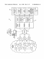
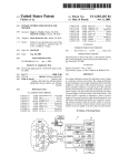
[0029] Referring noW to FIG. 1, an exemplary outage
noti?cation system 10 for detection and noti?cation in the
disruption of poWer supply at a customer location is illus
trated in accordance With at least one embodiment of the
present invention. In the illustrated example, the outage
noti?cation system 10 includes a plurality of outage detec
tion devices 12 capable of detecting the loss of poWer supply
on one or more circuits at the customer location. The outage
detection devices 12 are operable to communicate a status of
poWer supply at the circuit being monitored as either avail
able or unavailable. In this manner, a number of outage
detection devices 12 may be utiliZed at various positions at
the customer location, based upon the electrical topology
Within a particular structure, so that one or more electric
circuits may be monitored by one or more outage detection
devices 12. In one embodiment, a detector/controller device
13 is illustrated in communication With various detection
devices 12. The detector/controller device 13 may be imple
mented to include any available device operable or capable
of interfacing With or including a transducer to detect a value
and/or control some value. For example, and Without limi
tation, the detector/controller device 13 may be operable to
read or detect such values as
temperature; (ii) instanta
neous poWer consumption; (iii) energy consumption; (iv)
data from local energy consumption meter; (v) humidity;
(vi) carbon monoxide/dioxide levels; (vii) smoke; and (viii)
air pressure. The outage noti?cation system 10 may be
implemented to provide the values read or detected by the
detector/controller device 13 to a user When at certain
intervals, When requested, or When certain conditions or
limits are met. In still other embodiments, the detector/
controller device 13 may be used to control a device, such
as the temperature set point for an HVAC system.
[0030]
The outage noti?cation system 10 further may
include one or more communication devices 14 operable to
communicate With one or more of the outage detection
devices 12 at the customer location, and further operable to
communicate the status information relating to the poWer
supply at the customer location to a receiver system asso
ciated With the electric utility. In at least one embodiment,
the communication devices 14 implement some or all of the
features of the outage detection devices 12 With the addi
tional capability of communicating With the receiver system.
poWer supply at the customer location as detected by the
plurality of outage detection devices 12. In one embodiment,
the communication device 14 and the IVR system 16 may be
provided With dual-tone multifrequency (DTMF) commu
nication capabilities to reduce the amount of data commu
nicated betWeen the communication device 14 and the IVR
system 16 over the netWork 20, and also to reduce the setup
time to establish communications. The communication
device 14 also may be provided With modem capabilities to
facilitate communication With the modem data server 18 via
the netWork 20. In one embodiment, the communication
device 14 may be capable of communication With both the
IVR system 16 (e.g., using DTMF) and the modem data
server 18 (e.g., using modem techniques). In this instance,
the communication device 14 may be directed to initially
attempt to communication With one of the IVR system 16 or
the modem data server 18 and if the attempt fails or if the
communication device: 14 is otherWise directed, the com
munication device 14 may then attempt to communicate
With the other receiving system.
[0033] Further, the outage detection devices 12 or com
munication devices 14 may be adapted to receive and
implement softWare updates or other data provided by the
modem data server 18. Accordingly, the modem data server
18 may include, for example, one or more databases, such as
an inbound database 26 to receive data from the communi
cation device 14 and outage detection devices 12 and an
outbound database 28 including data to be transmitted to the
communication device 14, outage detection devices 12 and
possibly one or more of the detector/controller device 13 for
performing updates or providing additional information,
data, softWare or other functionality for the communication
devices 14, outage detection devices 12 or the detector/
controller device 13.
[0034] The modem data server 18 and the databases 26, 28
provide a high degree of functionality in that the commu
nication devices 14 and outage detection devices 12 may be
programmed, updated, or otherWise interact With the outage
noti?cation system 10 in an “on-the-?y” manner. This
update capability alloWs for continuing functionality to be
provided to the communication device 14 and outage detec
tion devices 12 Without the need to physically change out
Accordingly, reference to an outage detection device applies
these devices in the event of a change in function or
to a communication device, and vice versa, unless otherWise
noted.
operation of the outage noti?cation system 10, such as the
telephone number Where the communication device 14 calls
Apr. 1, 2004
US 2004/0061616 A1
or more major functionality, such as to modify the funda
mental manner and method by Which the outage detection
devices 12 communicate With one another, for example.
server 18, and/or through the information stored in the
various databases of modem data server 18.
In certain instances, it may be more ef?cient to
[0038] The present invention may include a peer-to-peer
communications protocol or system that alloWs the various
communicate certain data via one modem data server 18
outage detection devices 12 to communicate With one
instead of the IVR system 16. One example of such com
munication is Where the modem data server 18 provides the
communication device 14 With updated information or soft
another, in addition to communicating With communications
device 14. Similarly, the various detector/controller devices
[0035]
Ware or other programs or instructions related to the opera
13 may communicate With one another or With the outage
detection devices in a peer-to-peer manner, in addition to
tion of the communication device 14 or outage detection
communicating With communications device 14. In yet
devices 12 performing outage noti?cation services at the
customer location. Accordingly, the communication device
14 may be adapted to alternate betWeen communication With
another embodiment, an outage detection device 12 or a
detector/controller device 13 may be equipped to serve as a
the IVR system 16 and the modem data server 18 as
appropriate or as needed.
electrical outlet. In another embodiment, an outage detection
device 12 or a detector/controller device 13 may be designed
[0036] Although the outage detection devices 12 are
described herein primarily in the context of detecting poWer
to function as a panic or emergency button to dispatch
outages at a customer location, in various embodiments, the
outage detection devices 12 and/or the detector/controller
device 13 may be con?gured With one or more additional or
local telephone outlet, While only being plugged into a local
emergency personnel, such as ?re or ambulance, When
pushed. Such a system, in certain embodiments, may include
a battery backup and function even if poWer has been lost at
the facility. Emergency personnel Would be noti?ed through
alternate detection or measurement components for moni
the outage noti?cation system 10 using the receiver system.
toring or controlling other aspects of the customer location,
such as, for example, the temperature and/or humidity of one
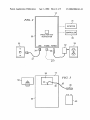
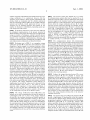
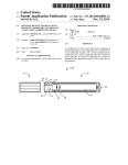
[0039] Referring noW to FIG. 2, an exemplary front vieW
of the communication device 14 is illustrated in accordance
or more areas of the customer location, the presence and/or
concentration of one or more chemical components (e.g.,
With at least one embodiment of the present invention. As
carbon monoxide) in the environment of the customer
location, the electric consumption or other utility consump
tion of the customer location, and the like. To illustrate,
Where the detector/controller device 13 is employed to
monitor temperature, a temperature monitoring device may
be provided to monitor the temperature, such as in a large
noted above, the communication device 14 and outage
detection device 12, in one embodiment, are substantially
similar except that the communication device 14 preferably
includes an additional capability of communicating With a
receiving system via a netWork. For ease of illustration, an
exemplary communication device 14 is discussed in detail
tion, or Within a room or area requiring a certain temperature
for performance, such as a computer clean room or food
beloW. Some or all of the folloWing description, hoWever,
also may apply to the outage detection devices 12 and/or the
detector/controller devices 13 Without departing from the
spirit or scope of the present invention.
storage room. These additional monitoring capabilities or
other services may be provided as applications 22 in com
munication With the receiver system, such as the IVR system
include a housing 30 constructed from any of a variety of
industrial refrigerator or food at a particular customer loca
16 and the modem data server 18.
[0037] It should be understood that the detector/controller
devices 13 may be implemented to detect or read virtually
any desired type of information. For example, detectors or
transducers may be implemented in any such device to
detect or read such information or conditions as
outage of
a 3-phase electric poWer circuit; (ii) temperature; (iii) instan
taneous poWer consumption; (iv) energy consumption; (v)
data from local energy consumption meter; (vi) humidity;
(vii) carbon monoxide/dioxide levels; (viii) smoke;
air
pressure;
outages of speci?c equipment;
building
[0040] As illustrated, the communication device 14 may
materials, such as plastic or polymeric materials, steel,
aluminum, or other Well-knoWn materials. Although the
housing 30 is illustrated as a substantially rectangular box,
it Will be appreciated that the housing 30 may be con?gured
in a number of shapes or dimensions as appropriate or
desirable for these purposes.
[0041] In at least one embodiment, the communication
device 14 may include not only the communication func
tionality so as to communicate With the modem data server
18 and/or IVR system 16 as described above, but also to
perform outage detection functionality provided by the
security system malfunctions; (xii) heat; (xiii) ?re; and (xiv)
outage detection devices 12. Accordingly, the communica
any of a variety of environmental readings. To implement
tion device 14 further may be provided With a circuit
interface for connecting the communication device 14 to the
respective circuit. The circuit interface may include any of
a variety of devices that may be utiliZed to couple to a circuit
such a system, the detector/controller device 13 Will inter
face With or can be implemented to include detectors as
desired. Such an implementation could be achieved by one
of ordinary skill in the art. It should also be understood that
the outage detection devices 12 or the detector/controller
devices 13 may be implemented to include devices to
and to detect the presence or absence of electrical poWer on
detector/controller devices 13 may be programmed or pro
the circuit. In one embodiment, the circuit interface includes
an AC adaptor 32 operable to be received by an outlet 33
(e.g., a standard home Wall poWer outlet) connected to a
circuit at the customer location to obtain alternating current
(AC) poWer from the circuit and transform the AC current to
direct current (DC) current for use in poWering the commu
vided data using one or more of the modules or applications
nication device 14. Although illustrated as separated from
of applications 22 in communication With the receiver
system, such as the IVR system 16 and the modem data
the housing 30, the AC adaptor 32 alternatively may be
con?gured to be integral With the housing 30.
remotely control other equipment, such as HVAC systems,
boilers, security systems, and virtually any device, system or
netWork capable of receiving electronic control signals. The
Apr. 1, 2004
US 2004/0061616 A1
Further, in at least one embodiment, the DC output
accordance With at least one embodiment of the present
(or absence thereof) of the AC adaptor 32 may be used by
invention. In the illustrated example, the communication
device 14 may be con?gured such that the housing 30 is
provided With a battery compartment 38 con?gured to
[0042]
the communication device 14 to monitor the status of poWer
supply for the circuit to Which the AC adaptor 32 is attached.
To illustrate, While DC poWer is received by the AC adaptor
32, the communication device 14 may regard the status of
the poWer supply as available (i.e., poWer is available in the
respective circuit). HoWever, When supply of DC poWer
receive one or more batteries 40 (e.g., a 9V battery). The
communication device 14 may be provided With a commu
nication line 42 connected at a ?rst end 44 to poWer the
communication device 14 and at a second end 46 to an
from the AC adaptor 32 ceases or is absent, the communi
adaptor 48 coupleable to the battery 40. The housing 30 may
cation device 14 may regard the status of the poWer supply
as unavailable (i.e., there is a poWer outage on the circuit).
[0043] The communication device 14 further may include
also be provided With a battery cover 50 connectable to the
positioned Within the battery compartment 38.
one or more netWork interfaces (e.g., communication jacks
[0047] During normal operation When poWer supply is
34, 36) for coupling to a netWork, such as a standard analog,
digital, cable or other phone or communications lines. In the
available at the customer location, the communication
device 14 may receive poWer primarily from the outlet 33
via the AC adaptor 32 (FIG. 2). In the event of a loss of
poWer supply on the circuit being monitored by the com
munication device 14, the communication device 14 may
sWitch to receive poWer from the battery 40 to continue
illustrated embodiment, the communication jack 34 includes
an analog telephone jack (e.g., a RJ-ll jack) used by the
communication device 14 to communicate over a telephone
or other netWork via, e.g., phone cord 37 connected to, for
example, a Wall telephone jack 35. Likewise, the commu
nication jack 36 may be provided for the convenience of the
customer so that a dedicated telephone jack is not required
and additional devices may utiliZe the same phone jack
While the communication device 14 continues to have com
munications access. Fax machines, telephones or modems
are examples of devices that may be coupled to the second
communication jack 36. Although FIG. 2 illustrates one
embodiment Wherein the communication device 14 imple
ments a connection to a telephone netWork for communica
housing 30 to cover the battery 40, When the battery is
operation.
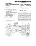
[0048] Referring noW to FIG. 4, an exemplary arrange
ment of outage detection devices to form a particular imple
mentation of the outage noti?cation system 10 is illustrated
in accordance With at least one embodiment of the present
invention. In the illustrated example, the outage noti?cation
system 10 includes a ?rst outage noti?cation device 60 and
a second outage noti?cation device 62, Which are similar to
the outage detection devices 12 illustrated in FIG. 1, and
tions purposes, in other embodiments the communication
Which are referred to as partner or “P1” devices herein. The
device 14 may implement a netWork interface to any of a
variety of netWorks, such as a coaxial cable jack for con
nection to a cable netWork, a Ethernet jack or other data
netWork jack for communication via a dedicated data net
Work, a modem chipset for data communications over a
communication device 64 substantially similar to the com
munication device 14 illustrated in FIGS. 1-3. Each of the
?rst and second outage detection devices 60 and communi
cation device 64 may be provided With batteries 40 and AC
telephone netWork, a Wireless or satellite transceiver, and the
like.
[0049] The ?rst and second outage detection devices 60,
[0044]
It should be appreciated that While the communi
cation device 14 is illustrated With the ?rst jack 34 and an
optional second jack 36 for adapting to a standard telephone
line, in other embodiments the communication device 14
may communicate With the receiving system (e.g., modem
data server 18 and IVR system 16) via the netWork 20 in a
Wireless, cellular, or other means of communication that
Would not require access to a Wired analog or digital
communication system. As such, the communication device
14 may be provided With Wireless capabilities for commu
nicating With the netWork 20, such as, for example, a 900
MHZ or 2.4 GHZ radio frequency (RF) transceiver com
monly used in Wireless telephones or a RF transceiver
compliant With one or more Wireless data netWork standards
such as IEEE 802.11a/b/g. Further, in the illustrated
example, the communication device 14 is provided With
modem capability for communicating, via a telephone net
Work or cable netWork system capable of DTMF signaling,
illustrated outage noti?cation system 10 also includes a
adaptors 32, as discussed above.
62 and the communication device 64 may be arranged to
receive electric poWer from respective circuits at the cus
tomer location during normal operation and, in the event of
a loss of poWer supply at the customer location or on a
particular circuit, the devices 60, 62 and 64 may be each
con?gured to sWitch to battery 40 poWer during an inter
ruption.
[0050] As With most customer locations, such as private
residences or business locations, poWer typically is received
from the electric utility through a meter and into a main
breaker box or fuse box 66. Although there are a number of
con?gurations of poWer supply, such as single and three
phase systems utiliZing various amounts of current and
voltage and having a number of fuse boxes, meters or mains,
a single fuse box 66 having a ?rst circuit 68, a second circuit
70 and a third circuit 72 Will be described for purposes of
With the IVR system 16, as Well as negotiating a data
clarity and simplicity herein. A plurality of devices or
appliances 74 may exist on each of the circuits 68, 70 and
72 Which may include outlets 76 into Which the AC adaptors
connection, such as via the Internet or a Wide area netWork
32 may be plugged to receive poWer and monitor the poWer
for communication With the modem data server 18.
supply on the respective circuits 68, 70 and 72.
[0045] The communication device 14, the outage detec
[0051] It Will be appreciated that While the ?rst and second
outage detection devices 60, 62 and communication device
tion device 12, or the detector/controller 13 may include a
detector for detecting.
[0046] Referring to FIG. 3, an exemplary back vieW of the
communication device 14 shoWn in FIG. 2 is illustrated in
64 are shoWn coupled in this manner, additional circuits 78
and additional outage detection devices 60, 62 may be
provided in various con?gurations such that all of the
Apr. 1, 2004
US 2004/0061616 A1
circuits at the customer location may be monitored or,
alternatively, only critical circuits may be monitored. Also,
the present invention may be employed for monitoring
poWer in front of and behind the meter (not shoWn) or in
front of the fuse boxes 66 or at various locations about the
customer’s residence or business Without departing from the
spirit and scope of the present invention as disclosed herein.
[0052] As previously discussed, the communication
device 14 may be provided With modem capabilities, such as
by providing a modem chipset 80 that is in communication
With the ?rst jack 34 Which may receive a connection to a
communicates the message to the microcontroller 82 of the
second outage noti?cation device 62. The communication
betWeen the devices 60-64 may occur in a serial manner
such that the ?rst outage noti?cation device 60 communi
cates With the second outage noti?cation device 62 infor
mation intended to be communicated to the communication
device 64. The second outage noti?cation device 62 then
transmits the information to the communication device 64.
In other embodiments, each of the devices 60, 62 and 64
may communicate With one another independently.
communication device 14 may also be provided With DTMF
[0055] In one embodiment, When the communication
device 64 is initialiZed for use, such as by removing it from
its shipping container and plugging it into the outlet 76 and
a telephone jack 35 via a phone cord 37, the communication
communication capabilities. The communication device 14,
device 64 may be con?gured to initiate a call With, or send
as Well as the ?rst and second outage detection devices 60,
62, also may be provided With one or more microcontrollers
82 or processors and, in the illustrated embodiment, an RF
transceiver 84 and antenna 86. The microcontrollers 82 may
include internal memory, or the devices may include exter
nal memory, Which is not speci?cally shoWn in FIG. 4.
a Welcome message to, the IVR system 16 (FIG. 1) to
provide the status of the communication device 64. Since the
devices 60-64 may be provided With batteries 40, the devices
[0053] In one embodiment, peer-to-peer Wireless tech
niques may be implemented to facilitate communications
betWeen the ?rst and second outage detection devices 60, 62
and communication device 64. Accordingly, the microcon
trollers 82 may be programmed to implement various fea
tures in accordance With peer-to-peer Wireless techniques,
for outage noti?cation, the communication device 64 may
also communicate With the IVR system 16 regarding the
status of the ?rst and second outage detection devices 60, 62
as provided by the devices 60, 62.
standard analog, digital or other telephone system for com
munication purposes (via, for example, Wall jack 35). The
such as self-addressing and automatic communications ini
tiation With other devices 60-64 by utiliZing a communica
tion protocol, such as BLUETOOTH, IEEE 802.11a/b/g or,
in the present embodiment, utiliZing technology described
and disclosed in International Patent Application PCT/
USOO/ 14240, ?led May 24, 2000, entitled “Wireless Trans
ceiver Network Employing Node-to-Node Data Messag
ing”, the entirety of Which is incorporated by reference
herein, Which may be referred to as MINIONNET technol
ogy. The Wireless communication disclosed in the above
referenced patent application is preferable to achieve Wire
less netWorking of intelligent transceiver nodes that employ
local processing and node-to-node data messaging to hand
off messages from an origination point to a destination point.
UtiliZing such technology, the ?rst outage noti?cation
device 60, When retrieved from the shipping container and
brought Within a certain range, such as three hundred feet,
may begin to communicate, via a radio frequency such as
900 MHZ or 2.4 GHZ. Such communication may be
encrypted or unencrypted as necessary or desirable.
[0054]
The ?rst outage noti?cation device 60 may self
address With respect to the other devices 62 and 64 in use at
the customer location Without the need to hardWire an
address, according to one embodiment. This enables a
number of devices to be dynamically employed Without the
need to con?gure the devices 60-64 in advance of the
installation. This provides one advantage of the present
invention to promote easy installation and con?guration of
the outage noti?cation system 10 and alloW communication
betWeen the devices 60-64 may then continue uninterrupted
in a Wireless manner. For example, the ?rst outage noti?
cation device 60 generates a message by the microcontroller
82 and transmits, via the RF transceiver 84 and antenna 86,
a signal intended for the second outage noti?cation device
62. The second outage noti?cation device 62 receives the
message via the antenna 86 and RF transceiver 84, and
60-64 may begin announcing and communicating With one
another even prior to being plugged into their respective
outlets 76. In any event, once the devices 60-64 are installed
[0056] Each of the devices 60-64 may implement the
microcontrollers 82, or other poWer detection circuitry
knoWn and available to one of ordinary skill in the art, to
monitor the external poWer being received via the AC
adaptors 32 from the outlet 76 and Wirelessly communicate
information regarding the status of poWer supply to one
another, as Well as to the communication device 64. In the
illustrated example, the communication device 64 has capa
bilities for monitoring the poWer supply of the respective
circuit 72 that are similar to the monitoring capabilities of
the ?rst and second outage detection devices 60, 62, as Well
as having communication capabilities for communicating
With the IVR 16 and/or the modem data server 18. Although
the illustrated outage noti?cation system implements a
single communication device 64 provided With this com
munication capability for ease of discussion, in other
embodiments, either or both of ?rst and second outage
detection devices 60, 62 may be provided With this addi
tional communication capability.
[0057] In one embodiment, the ?rst and second outage
detection devices 60, 62 and the communication device 64
are further provided With an indicator 96. The indicator 96
may be a light, such as a light emitting diode (LED), or a
speaker for providing status information to the customer or
a user of the outage noti?cation device 10. It may be
necessary to test or perform diagnostic routines on the
devices 60-64 and Will necessarily require feedback to the
tester, Which may be achieved by the indicator 96. In one
embodiment, the indicator 96 may include both a speaker to
sound When the battery is loW, for example, and multiple
LED lights, such as a red and a green LED for communi
cating information to the user of the present invention.
[0058]
The devices 60-64 further may provide alarms to
Warn or advise the customers about the status of, for
example, the battery. In this event, the microcontroller 82
may detect that the battery 40 is loW. The microcontroller 82
therefore may be con?gured to initiate a ?ashing of the LED
Apr. 1, 2004
US 2004/0061616 A1
light in a particular sequence to identify to a user that the
battery is loW and should be replaced. Where the indicator
96 is a speaker, the microcontroller 82 may initiate a beeping
or other sound, such as a voice, produced by the speaker to
alert the user as to the status of the battery 40. Similar
audible or visual signals may be provided by the indicator 96
With regard to a plurality of information such as When the
devices 60-64 detect that poWer supply has been lost on the
circuit being monitored. The indicator 96 may provide sound
or light sequences according to pre-de?ned criterion that
may be available in a user’s manual or on the devices 60-64,
so as to be readily available for the user to determine the
meaning of the particular sequence. In other embodiments,
communication device 64 and the IVR system 16, updated
information including When to update and the priority of the
update With the modem data server 18 may be provided as
Well. The communication device 64 may be further provided
With a memory device operable for receiving and storing
information from the ?rst and second outage detection
devices 60, 62, as Well as outage detection information
detected by the communication device 64.
[0062] The ?rst and second outage detection devices 60,
62 and the communication device 64 may include a plurality
of programmable parameters, such as to change the phone
number and time at Which communications are established.
the indicator 96 may produce recorded voice messages.
For example, one parameter establishes the minimum dura
tion of an outage before initiating a communication With the
[0059]
The devices 60-64 also may be provided With a test
IVR system 16 or modem data server 18, such as outages
button (not shoWn) to initiate a diagnostic routine to verify
lasting for 10 seconds, or perhaps 60 minutes prior to
reporting the outage. A number of other programmable
parameters may be included as desired and implemented by
that all of the components of the devices 60-64 are Working
properly. According to another embodiment, pressing the
test button may initiate communication With the IVR system
16 and/or modem data server 18 for diagnostic purposes or
for immediately initiating an outage noti?cation alert to the
receiver system, such as the IVR system 16. In one embodi
ment, the user depresses the test button (not shoWn) for
several seconds, such as for four seconds, and the ?rst
outage noti?cation device 60 begins sending RF packets. In
this embodiment, a red LED indicator 96 ?ashes While
packets are being sent. In response, the second outage
noti?cation device 62 and/or the communication device 64
send an acknowledgment. As RF communications are
received by the ?rst outage noti?cation device 60, a green
LED indicator 96 ?ashes to indicate that communications
are being successfully received. In this manner, the 2-Way
communication of the ?rst outage noti?cation device 60 may
be easily tested.
[0060] According to one embodiment the communication
device 64 may be provided With a heartbeat function for the
communication device 64 to initiate communication With the
IVR system 16 at a pre-determined minimum interval, such
as every 25 to 27 days, to provide routine interval status in
one of ordinary skill in the art.
[0063] According to one embodiment, the communication
device 64 may be provided With a real-time clock such that
When the communication device 64 communicates With the
IVR system and/or modem data server 18 the communica
tion device 64 receive the current date and time. When an
outage is detected by the ?rst or second outage detection
devices 60 or 62 or the communication device 64, the
communication device 64 may be able to log the eXact time
the outage occurred.
[0064] It Will be appreciated that because the time and
outages actually logged Would otherwise be the time the
communication device 64 reports the outage to the IVR
system 16 Which may be several minutes or longer in the
event of dif?culty obtaining access to the telephone system
or netWork 20. When the communication device 64 is
provided With a real-time clock that is periodically updated,
such as during the heartbeat function, the actual time the
outage occurred may be communicated to the IVR system
16 regardless of When the communication device 64 actually
establishes communication With the IVR system 16.
the event no other information or contacts have been made
[0065] It Will be appreciated that While the present system
betWeen the communication device 64 and the IVR system
is described as utiliZed for detecting outage for poWer
16 during that time period. During these communications,
supply, the ?rst and second outage detection devices 60, 62
the IVR system 16 may direct the communication device 64
to initiate a digital communication With the modem data
previously discussed, for detecting or monitoring other
and communication device 64 may also be employed, as
server 18 Which typically Would require disconnecting from
information, such as temperature or other values. Such
the IVR system 16 connection and establishing a connection
With the modem data server 18. The IVR system 16,
hoWever, may be in communication With the databases 26,
28 and obtain information to pass to the communication
device 64 during the heartbeat function. During the com
munication betWeen the communication device 64 and the
modem data server 18 diagnostics may be performed on the
information may be easily monitored With the addition of
communication device 64, as Well as the ?rst and second
outage detection devices 60, 62. In addition, the modem data
server 18 may provide the communication device 64 With
updated softWare or instructions for more ef?cient operation
or to modify speci?c capabilities or functionality of the
communication device 64 or the ?rst and second outage
detection devices 60, 62.
[0061] The IVR system 16, according to one embodiment,
initiates a communication With the communication device
64, such as by calling the communication device 64 directly
via the netWork 20. During any communication betWeen the
thermometer capability or other desired capability operably
provided on the devices 60-64.
[0066] Furthermore, the communication device 64 may be
in communication With a programmable thermostat, such
that communication betWeen the communication device 64
and the IVR system 16, or the modem data server 18 may
adjust the thermostat or other appliances or devices, such as
equipment or systems Within the customer location. In this
manner, a customer, returning from a vacation having pre
viously set the thermostat in a high energy conserving mode,
for eXample, may contact the IVR system 16 With regard to
the time the customer is returning and a desired thermostat
setting. The IVR system 16 may initiate a communication to
the communication device 64 Which Would operably adjust
the desired appliance or equipment.
[0067] Similarly, the ?rst and second outage detection
devices 60, 62 may be coupled to other programmable or
US 2004/0061616 A1
controllable appliances or equipment and such adjustments
may be communicated from the communication device 64 to
the ?rst and second outage detection devices 60, 62 and the
appropriate or desired changes Would be made to the pro
grammable settings of these coupled appliances or equip
ment.
[0068] In the present embodiment, the microcontroller 82
of the communication device 64 may receive information
from both the ?rst and second outage detection devices 60,
62 and intelligently process this information to determine
the status of poWer supply at the customer location. For
example, in the event the ?rst outage noti?cation device 60
detects loss of poWer supply on the circuit 68, the ?rst outage
noti?cation device 60 may then communicate this informa
tion to at least the communication device 64. The second
outage noti?cation device 62 may verify the status of poWer
supply on the second circuit 70 and determine Whether the
second circuit 70 has poWer supply available. The second
outage noti?cation device 62 may then communicate the
status of poWer supply at the second circuit 70 to the
communication device 64. The communication device 64
may determine the status of poWer supply at the third circuit
72 and determine Whether poWer supply at the third circuit
72 also is available. Using the status information regarding
the three circuits 68-72, the microcontroller 82 of the
Apr. 1, 2004
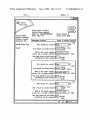
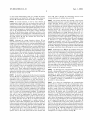
type of customer noti?cation. To illustrate, the Website may
include a Webpage (not shoWn) Whereby a customer may
input a customer ID and passWord to gain access to infor
mation and features associated With the customer. The
Website further may include a Webpage 100 for inputting
contact information for one or more entities associated With
the customer that are to be contacted in the event of a
detected poWer outage. The input contact information may
include, for example, the contacts’ names via name ?elds
102a-102c, methods of contacting the contacts (e.g., auto
mated telephone call, email, fax, pager, etc.) via contact
method ?elds 104a-104c and contact address associated
With the selected methods of contact (e.g., the contact’s
telephone, fax, or pager number, email address, etc.) via
address ?elds 106a-106c. Further, in at least one embodi
ment, the customer may indicate a desired delay after a
poWer outage before the respective entity is contacted by
entering a value representing the desired delay in the cor
responding delay ?elds 108a-108c. Additional or alternate
information and input ?elds may be implemented by the
Webpage 100 Without departing from the spirit or the scope
of the present invention.
[0073] After providing the contact information, the cus
tomer may submit the information, via the Website, to the
electric utility for use in contacting the customer’s repre
communication device 64 may determine Whether a poWer
sentatives in the event of a poWer outage at the customer
outage affects the entire electrical system at the customer
location or only a subset of circuits of the electrical system.
location. To illustrate by Way of example, assume that the
customer identi?es tWo employees, Roger and Mary, as
[0069]
In any event, the communication device 64,
according to one embodiment, may initiate a communication
With the IVR system 16 via the netWork 20, based on any
poWer outage detected on any of the circuits 68, 70 or 72 by
any of the devices 60-64. The communication device 64 may
then communicate the status of poWer supply detected by
each of the devices 60-64 to the IVR system 16 using DTMF
or other appropriate techniques.
[0070] As mentioned above, the communication device 64
and/or the outage detection devices 60 and 62 may include
a panic or emergency button to dispatch emergency person
nel, such as ?re or ambulance, When pushed. This may be
achieved using the IVR system 16 or the modem data server
18 through the netWork 20 so that emergency personnel may
be dispatched to the address associated With the device. This
provides the signi?cant advantage of providing emergency
panic buttons throughout a facility.
[0071]
contacts in the event of a poWer outage at the customer
location. Also assume that the customer indicates that Roger
is to be contacted by email immediately after a detected
poWer outage and by phone ?fteen minutes after the detected
poWer outage, as indicated by input provided by the cus
tomer in ?elds 102a, 102b, 104a, 104b, 106a, 106b, 108a
and 108b of the Webpage 100. Further, in the event that the
poWer outage continues for at least thirty-?ve minutes, the
customer may indicate that Mary is to be noti?ed by fax by
providing the corresponding information in ?elds 102c,
104c, 106c and 108c. Upon indication of a poWer outage at
the customer location received via the outage noti?cation
system 10 (FIG. 1), the receiving system or other system
associated With the electric utility may begin the process of
notifying the customer’s representatives in accordance With
the process indicated by the customer via the Webpage 100.
[0074] The Website or a telephone information netWork
also may provide additional information to the customer,
Referring noW to FIG. 5, an exemplary interface or
such as a log of prior events or a current status of the outage
Webpage 100 provided by an electric utility or other service
noti?cation system 10. To illustrate, the customer may be
interested in knoWing When a particular circuit has lost
provider is illustrated in accordance With at least one
embodiment of the present invention. As described in detail
herein, a customer may request that the outage noti?cation
system 10 notify the customer or the customer’s represen
tative of a poWer outage. When a customer requests outage
noti?cation service, the customer may provide information
relevant to the outage noti?cation, such as contact informa
tion for the appropriate individual(s) to be contacted, Where
the contact information may include, for example, fax
numbers, telephone numbers, pager numbers, or email
poWer, such as When a circuit provides poWer to devices that
are critical to the business or residence, or the customer may
desired information about the devices 60-64, such as oper
ating status or battery charge status. In this instance, the
Website may provide such information based on information
received from the devices 60-64.
[0075] Referring again to FIG. 4, the outage noti?cation
system 10 may be con?gured one or more of the customer’s
[0072] In at least one embodiment, the electric utility may
provide a Website Whereby this information may be input by
indicated representatives or the electric utility based at least
in part on the overall status of the poWer supply at the
customer location. For example, a poWer outage occurring
on only one of the circuits, such as the ?rst circuit 68, often
the customer at one or more Webpages of the Website and
indicates that the problem causing the poWer outage is local
then utiliZed by the electric utility to provide the requested
to the customer location and typically is not a result of a
addresses to contact in the event of an outage.
Apr. 1, 2004
US 2004/0061616 A1
failure on the electric grid of the electric utility. Accordingly,
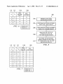
the outage noti?cation system 10 may be con?gured to
are Without poWer, but only When outages have been
detected by all of the devices 60 and 64 Will the electric
initiate a contact With the customer, but not With the electric
utility be noti?ed. Thus, the outage noti?cation system 10
utility, in such instances since a complete poWer outage has
may intelligently discern When a complete poWer outage has
not occurred and the loss of the poWer supply on the ?rst
circuit 68 is likely only a breaker or other localiZed problem
to the customer location. Alternatively, this information may
be provided by the customer to an electric utility represen
occurred at the customer location.
tative via telephone communications or one or more mailed
forms.
[0080]
The logic chart of FIG. 7 further illustrates the
ef?ciency of the present invention by producing only one
contact to the electric utility out of the eight possible
scenarios of poWer supply When detecting three circuits. The
addition of numerous circuits, monitored numerous outage
[0076] According to one embodiment, an intelligent out
age detection process may be performed by the microcon
troller 82 of the communication device 64 While in other
embodiments an intelligent outage detection process may be
performed by the IVR system 16 to more intelligently
respond to outages of poWer supply at the customer location.
The IVR system 16, according to one embodiment, may
communicate With the modem data server 18, and determine
an appropriate response to the outage noti?cation at the
customer location based on prede?ned criteria.
detection devices, generates a large number of potential
scenarios of the poWer supply at a particular customer
location that could produce false alarms or calls to the
electric utility reporting of an outage, When in fact only a
particular circuit or circuits have actually lost poWer. Thus,
the present invention provides for more ef?cient and effec
tive responses to detection and noti?cation in the event of
electrical poWer outage.
[0081]
Referring noW to FIG. 8, an exemplary outage
FIGS. 6 and 7 illustrate logic charts that may be
noti?cation method 200 is illustrated in accordance With at
least one embodiment of the present invention. The method
employed as ?rmWare or softWare by the microcontroller 82
200 initiates at block 202 Whereby the outage noti?cation
of the communication device 64, the IVR systems 16,
modem data server 18 or applications 22 (FIG. 1) to
outage detection devices 60, 62 and/or communication
[0077]
determine When to initiate communications With the cus
tomer and/or the poWer supply provider in the event of an
outage. The logic chart of FIG. 6 illustrates an exemplary
decision chart based on input received from the ?rst outage
noti?cation device 60 and the communication device 64.
The logic chart of FIG. 7 illustrates an exemplary decision
chart based on input received from both outage devices 60,
62 and the communication device 64. Those skilled in the art
may expand the logic charts to include any number of outage
detection devices using the teachings provided herein.
[0078]
Column 110 refers to the status of poWer supply as
detected by the communication device 64, and column 112
refers to the status of poWer supply as detected by the ?rst
outage noti?cation device 60. Column 118 refers to the
status of poWer supply as detected by the second outage
noti?cation device 62. Columns 114a, 116a of the logic
chart of FIG. 6 refer to the decision Whether to contact the
electric utility and the customer’s representatives, respec
tively, based on the corresponding statuses from columns
110 and 112. Similarly, columns 114b and 116b of the logic
chart of FIG. 7 refer to the decision Whether to contact the
electric utility and the customer’s representatives, respec
tively, based on the corresponding statuses from columns
110, 112 and 118. When these devices 60-64 detect that
poWer is available or on a “0” may be indicated and When
poWer is detected as unavailable or off a “1” may be
system 10 is provided as described above. One or more
devices 64 may be provided at a business or residential
customer location for monitoring a source of poWer.
[0082] The method provides, at block 204, for detecting
the status of poWer supply on the ?rst circuit 68 by the ?rst
outage noti?cation device 60. At block 206, the method
provides for detecting the status of poWer supply at the
second circuit 70, by the second outage noti?cation device
62. It Will be appreciated, hoWever, that in some embodi
ments, the second outage noti?cation device 62 may be
eliminated and only the communication device 64 may be
utiliZed When employing the method of the present inven
tion. In this instance, the communication device 64 may be
employed to monitor the second circuit 70 in instances
Where only tWo devices 60, 64 are employed.
[0083] At block 208, the communication device 64 ana
lyZes the status of poWer supply as detected on the ?rst and
second circuits 60 and 70 to determine Whether an outage
event or other monitored event has occurred. At block 210,
the method further includes notifying, such as by the com
munication device 64, the appropriate contact based on the
status of poWer supply on the ?rst and second circuits 68 and
70.
[0084]
In such instances, the communication device 64
may communicate With the IVR system 16 utiliZing, as
indicated in the corresponding columns 110, 112, and 118.
previously discussed, DTMF to perform this communication
exchange. In addition, the communication device 64 may
The corresponding decision to contact the electric utility or
customer may be indicated by a “Y” (yes) or “N” (no) in the
priate for transmitting and receiving additional information
respective columns 114a/114b and 116a/116b.
[0079] As the logic chart of FIG. 6 illustrates, a number of
different poWer con?gurations may be detected by both the
?rst outage noti?cation device 60 and communication
device 64, but only one of Which Would yield a call to the
electric utility. This is another advantage of the outage
noti?cation device 10 in that a number of poWer detection
scenarios may yield noti?cations to the customers or their
representatives, such as When a particular circuit or circuits
communicate With the modem data server 18 When appro
related to the operation and service of the ?rst and second
outage detection devices 60, 62 and communication device
64 or to provide detailed information to the modem data
server 18.
[0085] In one embodiment, the method 200 may further
include diagnostic routines, such as by pressing a test button
either unilaterally or in response to the indicator 96 prompt
ing a response by the user. The test initiating a diagnostic
routine of the outage prompting the communication device
Apr. 1, 2004
US 2004/0061616 A1
64 to initiate communication With the IVR system 16 and/or
function to periodically communicate With the IVR system
modem data server 18 for these purposes.
16 and modem data server 18 at pre-determined time inter
[0086]
vals. During such heartbeat communications, the IVR sys
tem 16 may designate the time, and priority of communi
In another embodiment, the transfer of information
betWeen the modem data server 18 and the communication
device 64 may include updates or upgrades to the micro
controller 82 or instructions utilized by the microcontroller
82 of the communication device 64 or the ?rst and second
outage detection devices 60 and 62. In one embodiment, the
method 200 includes indicating, by the indicator 96, a
sequence of perceptible light or sounds and associating a
meaning to the sequences.
cation to be established betWeen the communication device
64 and the modem data server 18 for receiving, for eXample,
programmable parameters to change settings or receive
upgrades from the modem data server 18.
[0092]
Based upon the type of outage that is detected, the
outage noti?cation system 10 may access the databases 26,
28 and initiate a communication With the appropriate con
tact. For eXample, the electric utility may be contacted When
a complete outage is detected or only the customer’s repre
[0087] The method 200 further may include the customer
of the outage noti?cation system 10 providing contact
information, such as email, pager or telephone contact
information, via a Webpage, telephone, or other means. The
sentatives may be contacted in the event of an outage on
only one or more of the circuits.
outage noti?cation system 10, (via the receiver system) may
[0093] Thus, it is apparent that there has been provided, in
contact the customer in the event of an outage detected. The
accordance With the present invention, an outage noti?cation
databases 26 and 28 of the outage noti?cation system 10
system and method that satisfy one or more of the advan
may be used for tracking or logging each event, such as a
tages set forth above. Although the preferred embodiment
loW battery, poWer outage, including the date, time and
has been described in detail, it should be understood that
various changes, substitutions, and alterations can be made
herein Without departing from the scope of the present
invention, even if all of the advantages identi?ed above are
not present. For eXample, the various elements or compo
duration of the outage. This and other associated data may
be accessible, such as via the netWork 20, by users of the
present invention.
[0088] In another embodiment, the method 200 provides
nents may be combined or integrated in another system or
for coupling the communication device 64 to the outlet 76 or
other connections to the circuits at the customer location
certain features may not be implemented.
and, in response thereto, the communication device 64
initiating a Welcome communication to the IVR system 16
and/or modem data server 18 indicating that the communi
cation device 64 is operational. Additional communications
may include handshakes or announcements betWeen the ?rst
and second outage detection devices 60 and 62 and the
communication device 64 so that the communication device
64 provides status information to the IVR system 16 and/or
modem data server 18 relevant to the outage detection status
of neWly connected devices such as the ?rst and second
[0094] Also, the techniques, systems, subsystems, and
methods described and illustrated in the preferred embodi
ment as discrete or separate may be combined or integrated
With other systems, modules, techniques, or methods With
out departing from the scope of the present invention. Other
items shoWn as directly coupled to each other may be
coupled through some other interface or device, such that the
items may no longer be considered directly coupled to each
other but may still be in communication With one another.
Other eXamples of changes, substitutions, and alterations are
outage detection devices 60, 62.
readily ascertainable by one skilled in the art and could be
made Without departing from the spirit and scope of the
[0089] In some embodiments, the communication
betWeen the ?rst and second outage detection devices 60, 62
present invention.
and the communication device 64 may be via RF commu
nication, While in other embodiments, the communication
betWeen these devices may occur via the poWer lines at the
customer location or the telephone lines Within the customer
location. In some embodiments the communication device
64 communicates With the IVR system 16 and modem data
server 18 via the modem chipset 80 and possibly through a
DTMF circuitry coupled to the communication device 64 via
a standard telephone netWork, While in other embodiments
the communication device 64 may communicate Wirelessly
With the IVR system 16 and modem data server 18.
[0090] The method 200 may also include detecting for
poWer supply While in other embodiments the method may
provide for monitoring temperature or other desired values
at the residence or business customer location. In one
[0095]
The present invention is not to be limited in scope
by the speci?c embodiments described herein. Indeed, vari
ous modi?cations of the present invention, in addition to
those described herein, Will be apparent to those of ordinary
skill in the art from the foregoing description and accom
panying draWings. Thus, such modi?cations are intended to
fall Within the scope of the folloWing appended claims.
Further, although the present invention has been described
herein in the context of a particular implementation in a
particular environment for a particular purpose, those of
ordinary skill in the art Will recogniZe that its usefulness is
not limited thereto and that the present invention can be
bene?cially implemented in any number of environments for
any number of purposes. Accordingly, the claims set forth
beloW should be construed in vieW of the full breath and
spirit of the present invention as disclosed herein.
embodiment, the communication device 64 is operable to
initiate communications With the IVR system 16 and/or
modem data server 18, While in other embodiments the
communication device 64 is able to receive communications
initiated by the IVR system 16 and/or modem data server 18.
What is claimed is:
1. An outage noti?cation system for detecting a poWer
outage at a customer location, the system comprising:
[0091] As previously discussed, the method 200 may
a ?rst device operably coupled to a ?rst circuit at the
include the communication device 64 initiating a heartbeat
customer location;
Apr. 1, 2004
US 2004/0061616 A1
11
a second device operably coupled to a second circuit at the
customer location;
Wherein the ?rst device is operable to:
10. The outage noti?cation system of claim 9, further
comprising the receiving system and Wherein the receiving
system is operable to notify the electric utility of the poWer
determine a status of poWer supply to the ?rst circuit;
and
outage When the statuses of poWer supply to the ?rst, second
and circuits indicate that poWer supply is unavailable in each
of the ?rst, second and third circuits.
11. The outage noti?cation system of claim 1, Wherein the
communicate the status of poWer supply to the ?rst
circuit to the second device;
?rst and second devices each include a Wireless transceiver
Wherein the second device is operable to:
determine a status of poWer supply to the second
circuit; and
notify, via a netWork, a receiving system associated
With the electric utility of a poWer outage at the
customer location based at least in part on the
statuses of poWer supply to the ?rst and second
circuits.
2. The outage noti?cation system of claim 1, further
comprising the receiving system and Wherein the receiving
system is operable to notify the electric utility of the poWer
outage When the statuses of poWer supply to the ?rst and
second circuits indicate that poWer supply is unavailable in
both the ?rst and second circuits.
3. The outage noti?cation system of claim 1, further
comprising the receiving system and Wherein the receiving
system is operable to notify at least one representative of a
customer of the poWer outage When the statuses of poWer
supply to the ?rst and second circuits indicate that poWer
supply is unavailable in at least one of the ?rst and second
circuits.
4. The outage noti?cation system of claim 3, Wherein the
receiving system is operable to notify the at least one
representative of the customer by transmitting an email to at
least one email address associated With the at least one
representative.
5. The outage noti?cation system of claim 3, Wherein the
receiving system is operable to notify the at least one
representative of the customer by transmitting a facsimile to
at least one facsimile number associated With the at least one
representative.
6. The outage noti?cation system of claim 3, Wherein the
receiving system is operable to notify the at least one
representative of the customer by transmitting a voice mes
sage to at least one telephone number associated With the at
least one representative.
7. The outage noti?cation system of claim 3, Wherein the
receiving system is operable to notify the at least one
representative of the customer by transmitting a page to at
least one pager number associated With the at least one
representative.
8. The outage noti?cation system of claim 1, further
comprising a third device operably coupled to a third circuit,
the third device operable to:
determine a status of poWer supply to the third circuit; and
communicate the status of poWer supply to the third
circuit to the second device.
and Wherein the ?rst device is adapted to communicate the
status of poWer supply to the ?rst circuit to the second device
via the Wireless transceiver.
12. The outage noti?cation system of claim 1, Wherein the
second device includes a netWork interface operably coupled
to the netWork for communicating With the receiver system
via the netWork.
13. The outage noti?cation system of claim 12, Wherein
the netWork includes a cable netWork.
14. The outage noti?cation system of claim 12, Wherein
the netWork includes a telephone netWork.
15. The outage noti?cation system of claim 14, Wherein
the receiver system includes integrated voice response (IVR)
system coupled to the telephone netWork and Wherein the
second device is adapted to communicate With the IVR
system via the telephone netWork using at least one dual
tone multifrequency (DTMF) signal.
16. The outage noti?cation system of claim 14, Wherein
the receiver system includes a modem data server coupled to
the telephone netWork and Wherein the netWork interface
includes a modem chipset for communicating With the
modem data server via the telephone netWork.
17. The outage noti?cation system of claim 1, Wherein the
?rst device includes an alternating current (AC) adaptor
operably connectable to an outlet associated With the ?rst
circuit and Wherein the ?rst device is adapted to determine
the status of poWer supply to the ?rst circuit based at least
in part on an output of the AC adaptor.
18. The outage noti?cation system of claim 17, Wherein
the second device includes an alternating current (AC)
adaptor operably connectable to an outlet associated With the
second circuit and Wherein the second device is adapted to
determine the status of poWer supply to the second circuit
based at least in part on an output of the AC adaptor of the
second device.
19. An outage detection device for detecting a poWer
outage in a circuit comprising:
a circuit interface operably coupleable to the circuit;
means for determining a status of poWer supply to the
circuit via the circuit interface; and
means for communicating the status of poWer supply to at
least one other outage detection device.
20. The outage detection device of claim 19, Wherein the
circuit interface includes an alternating current (AC) adaptor
operably coupleable to an outlet associated With the circuit.
21. The outage detection device of claim 20, Wherein the
means for determining a status of poWer supply to the circuit
includes a microcontroller operably coupled to the AC
adaptor and operable to determine the status of the poWer
supply of the circuit based at least in part on an output of the
9. The outage noti?cation system of claim 8, Wherein the
second device is operable to notify the receiving system of
AC adaptor.
a poWer outage at the customer location based at least in part
on the statuses of poWer supply to the ?rst, second and third
circuits.
22. The outage detection device of claim 20, Wherein the
outage detection device is poWered by an output of the AC
adaptor When poWer supply to the circuit is available.
Apr. 1, 2004
US 2004/0061616 A1
municating With the integrated voice response (IVR) system
23. The outage detection device of claim 22, further
comprising a battery for providing power to the outage
detection device When poWer supply to the circuit is unavail
via the telephone netWork using at least one dual-tone
able.
24. The outage detection device of claim 19, Wherein the
37. A method for notifying a customer of a poWer outage
at a customer location comprising:
multifrequency (DTMF) signal.
means for communicating the status includes a Wireless
transceiver operable to transmit a signal representative of the
status of the poWer supply to the circuit.
25. An outage detection device for detecting a poWer
outage at a customer location comprising:
determining a status of poWer supply to each of a plurality
of circuits at the customer location using a plurality of
outage detection devices, each outage detection device
operably coupled to a respective circuit of the plurality
of circuits; and
a circuit interface operably coupleable to a ?rst circuit at
the customer location;
means for determining a status of poWer supply to the ?rst
circuit via the circuit interface;
means for receiving a status of poWer supply to a second
circuit at the customer location; and
means for notifying a receiving system associated With
the electric utility of a poWer outage at the customer
location via a netWork based at least in part on the
status of the poWer supply to the ?rst and second
circuits.
26. The outage detection device of claim 25, Wherein the
circuit interface includes an alternating current (AC) adaptor
operably coupleable to an outlet associated With the ?rst
circuit.
27. The outage detection device of claim 26, Wherein the
means for determining a status of poWer supply to the ?rst
circuit includes a microcontroller operably coupled to the
AC adaptor and operable to determine the status of the
poWer supply to the ?rst circuit based at least in part on an
output of the AC adaptor.
28. The outage detection device of claim 26, Wherein the
outage detection device is poWered by an output of the AC
adaptor When poWer supply to the circuit is available.
29. The outage detection device of claim 28, further
comprising a battery for providing poWer to the outage
detection device When poWer supply to the circuit is unavail
able.
30. The outage detection device of claim 29, further
comprising an indicator for indicating a status of the battery.
31. The outage detection device of claim 25, Wherein the
means for receiving the status of the poWer supply to the
second circuit includes a Wireless transceiver operable to
receive a signal representative of the status of the poWer
supply to the second circuit.
32. The outage detection device of claim 31, Wherein the
signal representative of the status of the poWer supply to the
second circuit is transmitted from a second outage detection
device.
33. The outage detection device of claim 25, Wherein the
netWork includes a cable netWork.
34. The outage detection device of claim 25, Wherein the
netWork includes a telephone netWork.
35. The outage detection device of claim 34, Wherein the
receiving system includes a modem data server and Wherein
the means for notifying the electric utility of a poWer outage
includes a modem chipset adapted to communicate With the
modem data server via the telephone netWork.
36. The outage detection device of claim 34, Wherein the
receiving system includes an integrated voice response
(IVR) system and Wherein the means for notifying the
electric utility of a poWer outage includes means for com
notifying at least one representative of the customer of a
poWer outage at the customer location When the sta
tuses of poWer supply to the plurality of circuits indi
cate an unavailability of poWer supply to least one of
the plurality of circuits.
38. The method of claim 37, Wherein notifying the at least
one representative of the customer includes transmitting an
email to at least one email address associated With the at
least one representative.
39. The method of claim 37, Wherein notifying the at least
one representative of the customer includes transmitting a
facsimile to at least one facsimile number associated With
the at least one representative.
40. The method of claim 37, Wherein notifying the at least
one representative of the customer includes transmitting a
voice message to at least one telephone number associated
With the at least one representative.
41. The method of claim 37, Wherein notifying the at least
one representative of the customer includes transmitting a
page to at least one pager number associated With the at least
one representative.
42. The method of claim 37, further comprising notifying
an electric utility of a poWer outage at the customer location
When the statuses of poWer supply to the plurality of circuits
indicate an unavailability of poWer supply to each of the
plurality of circuits.
43. The method of claim 42, Wherein notifying the electric
utility of a poWer outage at the customer location includes
communicating an indication of a poWer outage to the
electric utility via a netWork.
44. The method of claim 43, Wherein the netWork includes
a cable netWork.
45. The method of claim 43, Wherein the netWork includes
a telephone netWork.
46. The method of claim 45, Wherein the receiving system
includes an integrated voice response (IVR) system and
Wherein communicating the indication of a poWer outage to
the electric utility includes communicating the indication of
a poWer outage to the IVR system via the telephone netWork
using at least one dual-tone multifrequency (DTMF) signal.
47. The method of claim 45 , Wherein the receiving system
includes a modem data server and Wherein communicating
the indication of a poWer outage to the electric utility
includes communicating the indication of a poWer outage to
the modem data via the telephone netWork.
48. The method of claim 37, Wherein determining a status
of poWer supply to each of a plurality of circuits at the
customer location includes:
coupling, for each of the plurality of circuits, an alternat
ing current (AC) adaptor to an outlet associated With
the circuit; and
Apr. 1, 2004
US 2004/0061616 A1
determining, for each of the plurality of circuits, an
availability of power supply to the circuit based at least
in part on an output of the AC adaptor coupled to the
outlet associated With the circuit.
49. A method for detecting a poWer outage a customer
location, the method comprising:
coupling an alternating current (AC) adaptor to an outlet
associated With a ?rst circuit at the customer location;
determining a status of poWer supply to the ?rst circuit
based at least in part on an output of the AC adaptor;
receiving a status of poWer supply to a second circuit at
the customer location; and
cornrnunicating, via a netWork, the statuses of poWer
supply to the ?rst and second circuits to a receiving
systern connected to the netWork and associated With an
electric utility.
50. The method of claim 49, Wherein the netWork includes
a cable netWork.
51. The method of claim 49, Wherein the netWork includes
a telephone netWork.
52. The method of claim 51, Wherein the receiving system
includes a modern data server connected to the telephone
netWork.
53. The method of claim 51, Wherein the receiving system
includes an integrated voice response (IVR) systern con
nected to the telephone netWorks.
*
*
*
*
*