1
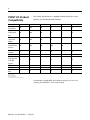
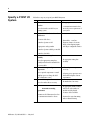
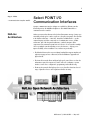
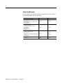
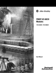
POINT I/O
SELECTION GUIDE
1734 AND
1734D SERIES
2
POINT I/O Family
The POINT I/O family has modular I/O modules that are ideal for applications where
flexibility and low-cost of ownership are key for successful control system design and
operation. As a key element in the Rockwell Automation Integrated Architecture, its
comprehensive diagnostics and configurable features allow the product to be easily
applied to any automation system and reduce engineering costs through
standardization. It can be used in remote device panels, local control panels, and can
be accessed from many locations including the Internet. This product has just-whatyou-need granularity in 1 to 8 points to reduce system cost and size.
The POINT I/O
System
POINT I/O has 4 major components:
y I/O modules provide the field interface and system-interface circuitry
y Communication interface modules provide the network-interface circuitry
y Terminal base units provide the wiring and signal termination for field-side
connections and system power for the backplane
y Power distribution modules provide the expandability of the POINT I/O system
and the flexibility to mix a variety of signal types
Publication 1734-SG001C-EN-P — May 2006
3
1734 POINT I/O modules offer 1 to 8 points per module. The I/O modules are
interfaced to a network through a communication interface, which includes a built-in
power supply that converts incoming 24V dc power to 5V dc backplane power. Each
type of communication interface supports a maximum of 13 to 17 I/O modules, with
a maximum of 10 A field power. The I/O modules receive power from the power
supply through the backplane. You can expand a POINT I/O assembly up to a
maximum of 63 I/O modules or 504 channels.
1734D Series POINTBlock I/O provides a DeviceNet communication interface with up
to 16 integrated I/O points in a single module. You can add up to 13 POINT I/O
modules to a POINTBlock I/O assembly, for a maximum of 120 channels per
assembly.
POINT I/O Features
y Highly modular design (1 to 8 point modularity)
y Broad application coverage
y Channel-level diagnostics (LED indicator and electronic)
y Channel-level alarm and annunciation (electronic)
y Parameter-level explicit messaging
y Removal and insertion under power (RIUP)
y Network solutions with multiple DeviceNet interfaces, ControlNet, EtherNet/IP, and
PROFIBUS DP adapters
y Channel-level open-wire detection with electronic feedback
y Vertical mounting without derating
y 5 g vibration
y Channel-level short-circuit detection with electronic feedback
y Flash upgradable adapters
y Electronic and mechanical keying
y Robust backplane design
y Hot swapping of I/O modules
y Built-in DIN-rail grounding
y Mounting base provides continuous backplane and field bus power
y Color-coded module labels
y UL, C-UL, CE, C-Tick, DeviceNet, EEx certifications (as marked)
y Highly reliable structural integrity
y Optical isolation between field and system circuits
Publication 1734-SG001C-EN-P — May 2006
4
The following chart illustrates the compatibility of POINT I/O with other control
platforms, especially within Rockwell Automation.
POINT I/O Product
Compatibility
PLC-5 with
Network Port
SLC 5/SLC 500
with Network
Port
PLC-5 Processor
via Network
Module
1756 Logix
Communication
Interface
PanelView
Terminal
RSLinx Software
1769-L20, -L30
Controller with
1761-NET
Interface
1769-L35E
SoftLogix 5800
PC with RSLinx
Only
1734-PDN
1734D
1734-ADN(X)
1734-ACNR
1734-AENT
1734-APB
IOD
IOD
IOD
NS
NS
NA
IOD
IOD
IOD
NS
NS
NA
IOD
IOD
IOD
NS
NS
3
IOD
IOD
IOD
IOD
IOD
3
NA
NA
NA
NA
NA
NA
NA
NA
NA
NA
NA
NA
NA
NA
NA
NS
NS
NA
NA
IOD
NA
IOD
NA
IOD
NA
IOD
IOD
IOD
NA
IOD
NS
NS
NS
NS
NS
NA
IOD = I/O Data
NS = Not Supported
NA = Not Applicable
3 = Requires third party scanner module
For information regarding POINT I/O on different networks, please refer to the
Selecting a Network Interface section in this document.
Publication 1734-SG001C-EN-P — May 2006
5
Communication
Considerations
POINT I/O features are impacted by your network choice.
Network
Impact
Each POINT I/O module will count as a
node on the main DeviceNet network.
DeviceNet 1734-PDN or 1734D
POINTBlock I/O
Total POINTBus backplane current of I/O
modules cannot exceed 1.3 A for the
1734-PDN or 1.0 A for a 1734D module.
Expansion power supplies may not be
used.
The 1734-ADNX expansion network port
allows for a DeviceNet subnet.
DeviceNet 1734-ADN(X)
A total of 63 POINT I/O modules can be
assembled on a single DeviceNet node.
Expansion power supplies may be used to
provide additional POINTBus backplane
current.
A total of 63 POINT I/O modules can be
assembled on a single ControlNet node.
ControlNet 1734-ACNR
Expansion power supplies may be used to
provide additional POINTBus backplane
current.
Up to 25 direct connections and 5 rack
connections are allowed.
A total of 63 POINT I/O modules can be
assembled on a single EtherNet/IP node.
EtherNet/IP 1734-AENT
Expansion power supplies may be used to
provide additional POINTBus backplane
current.
Refer to the User Manual to determine
the ratings for direct and rack
connections allowed.
A total of 63 POINT I/O modules can be
assembled on a single PROFIBUS DP
node.
PROFIBUS DP 1734-APB
Expansion power supplies may be used to
provide additional POINTBus backplane
current.
Publication 1734-SG001C-EN-P — May 2006
6
Specify a POINT I/O
System
Follow these steps as you specify your POINT I/O system:
9
Step
Remember to Select
1
Select a communication
interface
y the appropriate interface module
Choose the interface module for your
operating system.
y a communication interface that
meets the power requirements of
your system
2
Select I/O devices based on
field devices
y location of the device
y number of points needed
y appropriate catalog number
y I/O modules - some have
diagnostic features, electronic
fusing, isolated inputs/outputs,
and unique configurable features
y number of points available per module
y number of modules
3
Select a wiring base
assembly
Choose the appropriate wiring base
assembly with removable terminal block
for your modules.
4
Select optional power
components
Choose optional components to extend
backplane power or change the field
power distribution source.
5
Select optional accessories
y the appropriate wiring base
assembly
y additional power components as
necessary
y adequate power capacity to meet
I/O module backplane current
requirements
y the marker kit, if necessary
Choose the marker kit as necessary.
6
Determine mounting
requirement
Determine needed dimensions based on
the communication interface chosen.
Publication 1734-SG001C-EN-P — May 2006
y the appropriate number of DINrails based on the number of
modules and the physical
locations of those modules
y horizontal or vertical mounting
with no thermal derating
7
Step 1 - Select:
y a communication interface module
Select POINT I/O
Communication Interfaces
Separate communication interface adapters are available for different networks.
Install adapters into the POINTBus backplane to allow POINT I/O modules to
communicate with a controller.
NetLinx
Architecture
NetLinx open network architecture is the Rockwell Automation strategy of using open
networking technology for seamless, top-floor to shop-floor integration. The networks
in the NetLinx architecture ⎯ DeviceNet, ControlNet, and EtherNet/IP ⎯ speak a
common language and share a universal set of communication services. NetLinx
architecture, part of the Integrated Architecture, seamlessly integrates all the
components in an automation system from a few devices on one network to multiple
devices on multiple networks including access to the Internet ⎯ helping you to
improve flexibility, reduce installation costs, and increase productivity.
y The EtherNet/IP network is an open industrial standard that supports implicit and
explicit messaging and uses commercial, off-the-shelf Ethernet equipment and
physical media.
y The ControlNet network allows intelligent, high-speed control devices to share the
information required for supervisory control, work-cell coordination, operator
interface, remote device configuration, programming, and troubleshooting.
y The DeviceNet network offers high-speed access to plant-floor data from a broad
range of plant-floor devices and a significant reduction in wiring.
Publication 1734-SG001C-EN-P — May 2006
8
Select a Network
You can configure your system for information exchange between a range of devices
and computing platforms and operating systems.
Application Requirements
Network
Select
y Plant management (material handling)
y Configuration, data collection, and control on a single,
high-speed network
y Time-critical applications with no established schedule
y Data sent regularly
y Internet/Intranet connection
EtherNet/IP
1734-AENT
y High-speed transfer of time-critical data between
controllers and I/O devices
y Deterministic and repeatable data delivery
y Media redundancy
y Controller redundancy
y Intrinsic safety
y Redundant controller systems
ControlNet
1734-ACNR
y Connections of low-level devices directly to plant-floor
controllers, without interfacing them
y Data sent as needed
y More diagnostics for improved data collection and fault
detection
y Less wiring and reduced start-up time than a traditional,
hard-wired system
DeviceNet
1734-PDN
1734D
1734-ADN(X)
y Connecting to an existing PROFIBUS DP 5 m (16.4 ft) bus,
PROFIBUS
12 MB network
Publication 1734-SG001C-EN-P — May 2006
1734-APB
9
About the ControlNet Network
The 1734-ACNR adapter provides high-speed transfer of time critical data between
controllers and I/O devices. It manages data transfers between controllers on the
ControlNet network and POINT I/O modules plugged into the POINTBus backplane.
The ControlNet network, a communication architecture, allows the exchange of
messages between ControlNet products compliant with the ControlNet International
specification. The 1734-ACNR adapter features include a variety of control system
solutions, local communication network access through the network access port
(NAP), and redundant media. It requires Series C POINT I/O modules or later.
The 1734-ACNR adapter requires a typical 24V dc power supply with a maximum of
10.2 W of power. It provides a maximum backplane current of 1.0 A @ 5V dc.
Backplane current can be extended beyond 1.0 A with a 1734-EP24DC backplane
extension power supply. The 1734-EP24DC can supply up to an additional 1.3 A of
backplane current. Multiple 1734-EP24DC power supplies can be used to reach the
maximum limit of 63 POINT I/O modules if 25 or fewer of these modules are analog
or specialty modules.
The adapter supports 25 direct and 5 rack I/O connections to the POINT I/O
modules. From a single 1734-ACNR adapter, multiple controllers establish I/O
connections, up to a maximum of 5 rack I/O connections per adapter. Direct
connections must be used with analog and specialty modules. Multiple rack
connections permit multiple controllers to connect to I/O over a single 1734-ACNR
adapter. The number of connections that can be supported on a network depends on
the ControlNet parameters (NUT, RPI, and API) and the POINT I/O configuration by
itself (number and types of I/O modules).
The following example shows a single POINT I/O ControlNet adapter with 5
connections and 8 I/O modules. The POINT I/O modules are monitored by the 5
controllers on the ControlNet network. The POINT I/O modules in:
y slots 1, 3, and 5 are controlled by the first controller.
y slots 2 and 4 by the second controller.
y slot 6 by the third controller.
y slot 7 by the fourth controller.
y slot 8 by the fifth controller.
Publication 1734-SG001C-EN-P — May 2006
10
When using I/O modules with large amounts of data, it is important to be aware of the
1734-ACNR adapter's data capability. The 1734-ACNR adapter has 586 bytes of
memory available for scheduled transmit data. When developing an application, the
amount of data used by an individual connection must also include a small amount of
overhead (I/O bytes per connection).
The following formula tracks the amount of available scheduled transmit data.
Available Memory = 586 - [(Number of connections * 10) + Sum of all connection
sizes]
In the following example, the system uses a 1734-ACNR adapter with five
1734-232ASC modules.
Application Data Size (number of bytes)
Memory Required
1734-232ASC - 1 100
110
1734-232ASC - 2 88
98
1734-232ASC - 3 96
106
1734-232ASC - 4 96
106
1734-232ASC - 5 92
102
Total Bytes Used 472
522
In this example, a sixth module could be added if it used less than 54 bytes of application data. There are 64 bytes of memory
left. 64 = 586 - [(5 * 10) +472]
For more information about the 1734-ACNR adapter, see the POINT I/O ControlNet
Adapter User Manual, publication 1734-UM008.
Publication 1734-SG001C-EN-P — May 2006
11
Select the
DeviceNet
Communication
Interface
The POINT I/O family offers four interfaces for connecting to the DeviceNet network.
Refer to the following table.
For These Features
Remember
Select
y Cost-effective
y Electrically connects the main network to the I/O modules, which are connected on the
POINTBus backplane
1734-PDN
y Each I/O module counts toward the allowable limit of 63 nodes on the main network
y No configuration to the 1734-PDN communication interface necessary since it is transparent to
the main network
y Each POINT I/O module on the main network counts as a separate
node.
y Network distance limitations.
y Acts like a 1734-PDN communication interface, but uses a DeviceNet node number for the
y A POINT I/O expansion power supply is not permitted.
built-in 8 inputs and 8 outputs
y Appears to the main network as a 1734-PDN communication interface with a single, 16-point
1734D Series
module attached
y Any of the I/O modules may be attached in the same manner they are added to a 1734-PDN
communication interface
y Behaves as a slave device on the main network and a master on the POINTBus backplane
y Allows a group of I/O modules on the subnet to act as a single node on the main network
y RSNetWorx for DeviceNet software is needed for configuration of the 1734-ADN adapter on the
main network and the POINTBus backplane
y Configuration on the POINTBus backplane consists of a scan list that is very similar to those
used in all of the DeviceNet master scanner modules
y All POINT I/O modules count as a single node on the main
network.
y The main network distance is acceptable.
y POINT I/O expansion power supplies are permitted to add more
POINT I/O modules.
y Acts like a 1734-ADN adapter, with additional capabilities
y Has a second, Phoenix-style connector that extends the subnet off the module, so that any
DeviceNet-capable device could be connected to a subnet and scanned by the 1734-ADNX
adapter
y Node numbers of the devices on the POINTBus backplane and subnet would not count against
the 63 slave nodes allowed on the main network
y Data from these devices would be included in the data being sent to/from the 1734-ADNX
adapter on the main network
y Network on the second connector is electrically isolated from the main network and can be
used to extend the total DeviceNet trunk line distance
For example: with thick round media at 125 Kbps, you could run a maximum of 500 m (1640 ft)
to a 1734-ADNX adapter on the main network. You could then wire an additional 500 m (1640 ft)
of cable on the subnet connector and double the distance of the network. Remember that this
subnet needs terminating resistors and a 24V dc power connection, the same as any
other DeviceNet network.
y All POINT I/O modules, and some third-party field devices, count
as a single node on the main network.
y Devices on the subnet and the main network need to be connected
at different communication rates or use different sampling
methods (for example, change-of-state or polled).
1734-ADNX
y The main network distance is not acceptable and additional
distance is required.
y An expansion power supply may be required to add more
modules.
y POINT I/O expansion power supplies are permitted.
1734-ADN
Publication 1734-SG001C-EN-P — May 2006
12
With the introduction of the 1734-232ASC module, the amount of data to be
transferred over the subnet could become substantial. This could also occur with the
1734-ADNX adapter and the standard DeviceNet devices connected to its subnet
connector. It is important that the total amount of data coming from the subnet does
not exceed the data capability of either the 1734-ADN or 1734-ADNX adapter.
y 250 bytes (248 data + 2 bytes command info) for output data (used as either COS,
cyclic, or poll)
y 250 bytes (248 data + 2 bytes status info) for polled input data
y 250 bytes (248 data + 2 bytes status info) for COS/cyclic input data
y 8 bytes (6 data + 2 status info) for strobe input data
The data coming through the 1734 adapter combined with the other data from the
main network cannot exceed the data capability of the main network master scanner.
If this occurs, you will need multiple master scanners on the main network and the
I/O modules on the subnet will need to be split between multiple 1734-ADN or 1734ADNX adapters. With the 1734-PDN communication interface, the multiple masters on
the main network will be able to communicate to separate groups of modules on its
subnet through the same 1734-PDN communication interface, so no additional
adapter would be necessary.
Publication 1734-SG001C-EN-P — May 2006
13
About the EtherNet
I/P Network
The 1734-AENT adapter supports direct- and rack-optimized connections. A direct
connection is a real-time data transfer link between the controller and whatever
module occupies the slot that the configuration data references. Direct-connection
messaging occurs at a cyclic rate specified by the requested packet interval (RPI)
during configuration. A rack-optimized connection is a grouping of data from more
than one I/O module into a single block of data sent over a single connection at the
same data rate. Rack-optimized connections reduce the total number of connections
needed to transfer data when using many I/O modules in a system.
Assume a system contains 8 digital I/O modules interfaced to a 1734-AENT adapter. If
you used direct connections to transfer data to each of these modules, you need 8
connections ⎯ one to each of the 8 I/O modules. If you use a rack-optimized
connection to transfer the data, you need only a single connection ⎯ the connection
to the 1734-AENT adapter.
Publication 1734-SG001C-EN-P — May 2006
14
About the 1734D
Series
The 1734D series is a set of DIN-rail mounted products with an integrated DeviceNet
communication interface, various combinations of onboard I/O points, removable
terminations, and a POINTBus expansion port.
The DeviceNet interface presents the integrated I/O as a single DeviceNet node while
expansion I/O modules will appear as separate nodes.
The 1734D series includes a nonisolated DeviceNet communication interface. The
24V dc from the DeviceNet connection powers a nonisolated dc/dc converter that
generates +5V dc. This +5V dc powers the 1734D series electronics and connects to
the PointBus port to power the expansion I/O electronics.
Connect whatever field power you supply to the internal field-power bus. For
example, if 120V ac is applied to the power connections, there will be
120V ac applied to the modules through the internal field-power bus.
POINT I/O modules to the right of the 1734D products will also have that internal
power bus voltage applied, unless you use a 1734-FPD to interrupt and change the
field power-bus voltage.
Publication 1734-SG001C-EN-P — May 2006
15
POINTBlock I/O Typical Wiring
Some POINT I/O modules are isolated from the field bus power. Be sure to check the
I/O module wiring diagram and user manual to determine actual power source wiring
requirements.
Cat. No.✶
1734D-IA16(S)
1734D-IB16(S)
1734D-IB8XOB8E(S)
1734D-IB8XOW8(S)
1734D-IA8XOA8(S)
1734D-IA8XOW8(S)
Description
120V ac 16 Input Module, Cage-clamp
12/24V dc 16 Input Module, Cage-clamp
24V dc 8 Input/8 Output Module, Cage-clamp
24V dc 8 Input/8 N.O. Relay Module, Cage-clamp
120V ac 8 Input/8 Output Module
120V ac 8 Input/8 N.O. Relay Module, Cage-clamp
✶Catalog numbers ending in S indicate the spring-clamp style.
Publication 1734-SG001C-EN-P — May 2006
16
Step 2 - Select:
y I/O modules - some modules have
diagnostic features, electronic
fusing, or individually isolated
inputs/outputs
Select POINT I/O Modules
The POINT I/O family provides a wide range of input and output modules to span
many applications, from high-speed digital to process control. POINT I/O modules
support producer/consumer technology, which allows input information and output
status to be shared among multiple Logix controllers.
Each POINT I/O module mounts adjacent to the network adapter or another I/O
module and removable terminal block (RTB) to connect all field-side wiring. The
RTBs are part of the terminal base assembly (1734-TB, 1734-TB3, 1734-TBS, 1734TB3S, 1734-TBCJC). They are not included with the I/O modules and must be
ordered separately.
The POINT family of I/O modules includes:
y 1734 digital I/O modules.
y 1734 analog I/O modules.
y 1734 specialty I/O modules.
y 1734 wiring systems.
y 1734 network communication adapters.
Publication 1734-SG001C-EN-P — May 2006
17
Digital I/O Modules
Choose digital I/O modules when you need:
y Input modules.
An input module responds to an input signal in the following manner:
- Input filtering limits the effect of voltage transients caused by contact bounce
and/or electrical noise. If not filtered, voltage transients could produce false data.
All input modules use input filtering.
- Optical isolation shields logic circuits from possible damage due to electrical
transients.
- Logic circuits process the signal.
- An input LED indicator turns on or off indicating the status of the corresponding
input device.
y Output modules.
An output module controls the output signal in the following manner:
- Logic circuits determine the output status.
- An output LED indicator indicates the status of the output signal.
- Optical isolation separates module logic and bus circuits from field power.
- The output driver turns the corresponding output on or off.
y Surge suppression.
Most output modules have built-in surge suppression to reduce the effects of highvoltage transients. However, we recommend that you use an additional suppression
device if an output is being used to control inductive devices, such as:
- relays.
- motor starters.
- solenoids.
- motors.
Additional suppression is especially important if your inductive device is in series
with or parallel to hard contacts, such as push buttons or selector switches.
The 1734 digital I/O modules support:
y a wide variety of voltage interface capabilities.
y isolated and non-isolated module types.
y point-level output fault states.
y choice of direct-connect or rack-optimized communications.
y field-side diagnostics on select modules.
Publication 1734-SG001C-EN-P — May 2006
18
Digital AC Input Modules
1734-IA2
1734-IM2
Number of Inputs
2
Voltage, On-State Input, Nom.
120V ac
220V ac
Voltage, On-State Input, Min.
65V ac
159V ac
Voltage, On-State Input, Max.
132V ac
264V ac
20 ms hardware filter plus 0…65 ms digital filter programmable in increments
Input Delay Time, ON to OFF, Hardware Delay, Max.
of 1 ms✶
Current, On-State Input, Min.
3.7 mA
5.7 mA
Input Impedance, Nom.
10.6 kΩ
22.3 kΩ
Current, Off-State Input, Max.
2.5 mA
2.9 mA
Terminal Base Unit
1734-TB or 1734-TBS
PointBus Current (mA)
75
Power Dissipation, Max.
0.7 W @ 28.8V dc
✶Input ON-to-OFF delay time is the time from a valid input signal to recognition by the module.
Digital AC Output Module
1734-OA2
Number of Outputs
2
Voltage, On-State Output, Nom. 120V ac, 220V ac
Voltage, On-State Output, Min. 74V ac
Voltage, On-State Output, Max. 264V ac
Output Current Rating
1.5 A (2 channels @ 0.75 A each)
Terminal Base Unit
1734-TB or 1734-TBS
PointBus Current (mA)
75
Power Dissipation, Max.
0.8 W @ 28.8V dc
Digital DC Input Modules
1734-IB2
1734-IB4
1734-IB8
Sinking Input Modules
Number of Inputs
2
4
1734-IV2
1734-IV4
1734-IV8
Sourcing Input Modules
8
2
4
8
1734-TB or
1734-TBS
1734-TB,
1734-TBS,
1734-TB3, or
1734-TB3S7
1734-TB or
1734-TBS
1.0 W @
28.8V dc
1.6 W @ 28.8V
dc
Voltage, On-State Input, Nom. 24V dc
Voltage, On-State Input, Min. 10V dc
Voltage, On-State Input, Max. 28.8V dc
Input Delay Time, ON to OFF 0.5 ms hardware + (0…65 ms selectable)✶
Current, On-State Input, Min. 2 mA
Current, On-State Input, Max. 5 mA
Current, Off-State Input, Max. 1.5 mA
Terminal Base Unit
1734-TB or
1734-TBS
1734-TB,
1734-TBS,
1734-TB3, or
1734-TB3S7
1734-TB or
1734-TBS
PointBus Current (mA)
75
Power Dissipation, Max.
0.7 W @ 28.8V 1.0 W @ 28.8V 1.6 W @ 28.8V 0.7 W @
dc
dc
dc
28.8V dc
Thermal Dissipation, Max.
2.4 BTU/hr @
28.8V dc
3.4 BTU/hr @
28.8V dc
5.5 BTU/hr @
28.8V dc
2.4 BTU/hr @ 3.4 BTU/hr @
28.8V dc
28.8V dc
✶Input ON-to-OFF delay time is the time from a valid input signal to recognition by the module.
71734-TB3 or 1734-TB3S recommended.
Publication 1734-SG001C-EN-P — May 2006
5.5 BTU/hr @
28.8V dc
19
Digital DC Output Modules
1734-OB2✶
1734-OB2E
1734-OB2EP
1734-OB4✶
1734-OB4E
1734-OB8✶
1734-OB8E
1734-OV2E
Sourcing Output Modules
Number of Outputs
1734-OV4E
1734-OV8E
Sinking Output Modules
2
4
8
2
4
8
2.0 A max per
module, 1.0 A
per output
3.0 A per
module, 1.0 A
per output
3.0 A per
module, 1.0 A
per channel
0.8 W max @
28.8V dc
1.2 W max @
28.8V dc
2.0 W max @
28.8V dc
Voltage, On-State Output, Nom. 24V dc
Voltage, On-State Output, Min. 10V dc
Voltage, On-State Output, Max. 28.8V dc
Output Current Rating, Max.
2.0 A per module, 1.0 A per
channel
Terminal Base Unit
1734-TB or 1734-TBS
PointBus Current (mA)
75
Power Dissipation, Max.
0.8 W @ 28.8V dc
4.0 A per
module, 2.0 A
per channel
3.0 A per module, 1.0 A per channel
3.4 W @ 28.8V
1.2 W @ 28.8V dc
dc
2.0 W @ 28.8V dc
✶ Non-diagnostic, standard output modules.
Digital Contact Output Modules
1734-OW2
1734-OW4
Number of Outputs
2 Form A (N.O.) relays, non-isolated or isolated
4 Form A (N.O.) relays, isolated
1734-OX2
Output Delay Time, ON to OFF, Max.
26 ms✶
Contact Resistance, Initial
30 mΩ
2 Form C (N.O./N.C.) relays, isolated
10 ms✶
2.0 mA and bleed resistor thru snubber circuit @
240V ac
Leakage Current, Off-State Output, Max 1.2 mA and bleed resistor thru snubber circuit @ 240V ac
Terminal Base Unit
1734-TB or 1734-TBS
PointBus Current (mA)
80
Power Dissipation, Max.
0.5 W
100
✶Time from valid output off signal to relay deenergization by module.
Digital POINTBlock AC/DC Modules
1734D-IA16,
1734D-IA16S
1734D-IA8XOA8,
1734D-IA8XOA8S
1734D-IA8XOW8,
1734D-IA8XOW8S
1734D-IB16,
1734D-IB16S
1734D-IB8XOB8E,
1734D-IB8XOB8ES
1734D-IB8XOW8,
1734D-IB8XOW8S
Number of Inputs
16
8
8
16
8
8
Number of Outputs
⎯
8
8
⎯
8
8
Voltage, On-State Input, Nom. 120V ac
Input Delay Time, ON to OFF
20.0 ms hardware +
(0…65 ms selectable)
Current, On-State Input, Min.
5.0 mA
120V ac
120V ac
24V dc
24V dc
24V dc
20.0 ms hardware +
(0…65 ms selectable)
20.0 ms hardware +
(0…65 ms selectable)
0.5 ms hardware +
(0…65 ms selectable)
0.5 ms hardware +
(0…65 ms selectable)
0.5 ms hardware +
(0…65 ms selectable)
5.0 mA
5.0 mA
2.5 mA
2.5 mA
2.5 mA
Current, On-State Output, Min. ⎯
10 mA per output
10 mA per output
⎯
⎯
10 mA per output
PointBus Current (mA)
1000
1000
1000
1000
1000
1000
Power Dissipation, Max.
2.0 W @ 24V dc
2.0 W @ 24V dc
2.0 W @ 24V dc
2.0 W @ 24V dc
2.0 W @ 24V dc
2.0 W @ 24V dc
Publication 1734-SG001C-EN-P — May 2006
20
Analog, Thermocouple, and RTD I/O
Modules
The POINT I/O analog and temperature I/O modules support: on-board, channel-level
data alarming (four set-points per channel); scaling to engineering units; channellevel diagnostics (electronic bits and LED indicators); and integer format.
Choose analog, thermocouple, or RTD I/O modules when you need:
y Individually configurable channels of POINT I/O for use with a variety of
sensors.
y On-board scaling eliminates the need to scale the data in the controller.
Controller processing time and power are preserved for more important tasks, such
as I/O control, communications, or other user-driven functions.
y Online configuration. You can configure modules in the Run mode by using the
programming software or the control program. This lets you change configuration
while the system is operating. For example, the input filter for a particular channel
could be changed, or a channel could be disabled based on a batch condition. To
use this feature, the controller and network interface must also support
this feature.
y Over- and under-range detections and indications eliminate the need to test
values in the control program, saving valuable processing power of the controller.
In addition, since alarms are handled by the module, the response is faster and only
a single bit per channel is monitored to determine if an error condition has
occurred.
y Ability to direct output device operation during an abnormal condition.
You can individually configure each channel of the output module to hold its last
value or assume a user-defined value on a fault condition. This feature lets you set
the condition of your analog devices, and therefore your control process, which
may help to ensure a reliable shutdown.
y Ability to individually enable and disable channels. Disabling unused
channels improves module performance.
y Selectable input filters lets you select from several different filter frequencies for
each channel that best meets the performance needs of your application based on
environmental limitations. Lower filter settings provide greater noise rejection and
resolution. Higher filter settings provide faster performance. The analog modules
provide four input filter selections; RTD and thermocouple modules
provide six.
y Selectable response to broken input sensor. This feature provides feedback to
the controller that a field device is not connected or operating properly. This lets
you specify corrective action based on the bit or channel condition.
y High Accuracy. The modules share a high accuracy rating of ±0.1% of full-scale
accuracy @ 25 °C (77 °F).
Publication 1734-SG001C-EN-P — May 2006
21
Analog Input Modules
1734-IE2C
1734-IE2V
1734-IR2✶
1734-IT2I✶
4…20 mA
0…20 mA
0…10V
±10V
0…600 Ω
±75 mV
16 bits - over 21 mA
0.32 μA/cnt
15 bits plus sign
320 μV/cnt in unipolar or bipolar
mode
16 bits - 9.5 mV per count
0.03 °C per count (pt 385 @ 25 °C)
15 bits plus sign2.5 mV per count7
Voltage Input: 0.1% Full Scale @ 25
°CI§
Current Input: 0.1% Full Scale @ 25 °C
Voltage Input: 0.1% Full Scale @ 25
Voltage Input: 0.1% Full Scale @ 25
°C‡
°C‡
Number of Inputs
2
Input Signal Range
Input Resolution, Bits
Data Format
Signed integer
Absolute Accuracy, Analog Inputs
Current Input: 0.1% Full Scale @ 25
°C‡
⎯
Accuracy Drift w/Temp., Analog Inputs Current Input: 30 ppm/°C
Input Step Response, per Channel
70 ms @ Notch = 60 Hz (default)
80 ms @ Notch = 50 Hz
16 ms @ Notch = 250 Hz
8 ms @ Notch = 500 Hz
⎯
Input Conversion Type
Delta Sigma
⎯
Terminal Base Unit
1734-TB or 1734-TBS
PointBus Current (mA)
75
220
Keyswitch Position
3
6
Power Dissipation, Max.
0.6 W @ 28.8V dc
1734-TBCJC
0.75 W @ 28.8V dc
175
1.0 W
✶ Analog and temperature input modules support the following configurable parameters and diagnostics:
y open-wire detection with LED and electronic reporting
y four-alarm and annunciation set-points: low alarm; high alarm; low/low alarm; high/high alarm
y calibration mode detection and electronic reporting
y under-range detection and electronic reporting
y over-range detection and electronic reporting
y channel signal range and on-board scaling (scaling to any 16-bit integer under-/over-range alarms)
y filter type (notch for A/D, or first-order low-pass digital filter)
y temperature scale (Celcius, Fahrenheit, Kelvin, Rankine, or custom)
y channel update rate (step response plus 0-10,000 ms filter setting)
7Also see thermocouple type.
‡Includes offset, gain, non-linearity and repeatability error terms.
§ncludes offset, gain, non-linearity and repeatability error terms.
Analog Output Modules
1734-OE2C
1734-OE2V
Number of Outputs
2
Output Signal Range
4…20 mA
0…20 mA
0…10V
±10V
Output Resolution, Bits
13 bits - over 21 mA
2.5 μA/cnt
14 bits (13 plus sign)
1.28 mV/cnt in unipolar or bipolar mode
Data Format
Signed integer
Absolute Accuracy, Analog Outputs
Current Output: 0.1% Full Scale @ 25 °C✶
Accuracy Drift w/Temp., Analog Outputs
Current Output: 30 ppm/°C
Voltage Output: 0.1% Full Scale @ 25 °C7
Voltage Output: 5 ppm/ ºC
Step Response to 63% of FS, Current Output 24 μs
⎯
Step Response to 63% of FS, Voltage Output ⎯
20 μs
Output Conversion Rate
16 μs
Terminal Base Unit
1734-TB or 1734-TBS
PointBus Current (mA)
75
Keyswitch Position
4
Power Dissipation, Max.
1.0 W @ 28.8V dc
20 μs
✶Includes offset, gain, non-linearity and repeatability error terms.
7Includes offset, gain, non-linearity and repeatability error terms
Publication 1734-SG001C-EN-P — May 2006
22
Use Temperature
Module Alarms
POINT I/O temperature modules can detect and communicate these electronic
conditions:
y Over-range alarm
y Under-range alarm
y Level alarm (low-low, low, high, high-high)
y Open-wire alarm
Over-Range Alarm
The channel over-range alarm is set if the input is greater than the maximum
temperature (thermocouple or RTD range dependent), millivolt (+75V) or resistance
(600 Ω) range value, or above the maximum range of the thermocouple or RTD.
The cold-junction compensator has its own over-range alarm. If the CJC temperature
goes above 70 °C (158 °F), the over-range alarm is set.
Under-Range Alarm
The channel under-range alarm is set if the input is less than the minimum
temperature (thermocouple or RTD range dependent), millivolt (-75 mV) or
resistance (10 Ω) range value, or below the minimum range of the thermocouple or
RTD.
The cold-junction compensator has its own under-range alarm. If the CJC temperature
goes below 0 °C (32 °F), the under-range alarm is set.
Level Alarms
There are four level alarms.
y Low
y Low-low
y High
y High-high
When the channel input goes below a low alarm or above a high alarm, a bit is set in
the data table. All alarm status bits can be read individually or by reading the channel
status byte (bits 2 to 5 for channel 0; bits 10 to 13 for channel 1).
Each channel alarm can be configured individually.
Publication 1734-SG001C-EN-P — May 2006
23
Open-wire Alarm
The module has the ability to check for a broken or detached wire. In any mode, if a
broken/detached lead is detected, the data value is forced to maximum and the overrange alarm is set. Once the alarm is issued, it remains active as long as the input
signal is faulted.
Cold-junction
Compensation
(1734-IT2I only)
When using thermocouples, cold-junction compensation is required at the
termination of the thermocouple wire. Cold-junction can be accomplished in three
ways:
y Enter an estimated temperature
y Use a 1734-TBCJC mounting base (recommended)
y Use external cold-junction compensators
Entering an estimated temperature is the least accurate way for cold-junction
compensation. Using external compensators is the most expensive way, while using the
1734-TBCJC provides the easiest and most accurate method.
An open cold-junction compensator causes the input point to the maximum
temperature value for the selected input type. This will cause an alarm to be set. Once
the alarm is issued, it remains active as long as the input signal is faulted (above
maximum).
Cold-junction Enable (1734-IT2I only)
Set this bit to enable or disable the cold-junction linearization. If enabled, the proper
cold-junction compensation value will be applied to the selected thermocouple. If
disabled, the data (CJ temperature) will still be available but not applied to the input.
If the 1734-TBCJC is not available, this parameter should be set to disabled. A coldjunction value can be added using the cold-junction offset parameter.
Noise Filtering
(1734-IR2 only)
You can select the type and amount of noise filtering on each individual channel.
y Notch filter of analog to digital converter
y First-order, low-pass digital filter
Choose the filter that provides you with the update and step response that most closely
matches your system requirements.
Publication 1734-SG001C-EN-P — May 2006
24
POINT I/O Temperature Input Module Specifications
1734-IR2
Input Resolution, Bits
16 bits
Thermocouple Type and Resolution Average Over Span ⎯
1734-IT2I
15 bits plus sign
Type B, 30…1820 °C, 3 counts/ °C
Type C, 0…2315 °C, 6 counts/ °C
Type E, -270…1000 °C, 24 counts/ °C
Type J, -210…1200 °C, 21 counts/ °C
Type K, -270…1372 °C, 13 counts/ °C
Type N, -270…1300 °C, 11 counts/ °C
Type R, -50…1768.1 °C, 4 counts/ °C
Type S, -50...1768.1°C, 4 counts/°C
Type T, -270…400 °C, 15 counts/ °C
Cold Junction Compensation
⎯
Included in 1734-RTBCJC Remote Termination Block
Cold Junction Compensation Range
⎯
0…70 °C
Absolute Accuracy, Analog Inputs
Current Input: 0.1% Full Scale @ 25 °C
Voltage Input: 0.1% Full Scale @ 25 °C7
Input Update Rate, per Module
20 ms @ Notch = 50 Hz
17 ms @ Notch = 60 Hz (default)
10 ms @ Notch = 100 Hz
8 ms @ Notch = 120 Hz
5 ms @ Notch = 200 Hz
4 ms @ Notch = 240 Hz
3 ms @ Notch = 300 Hz
3 ms @ Notch = 400 Hz
2 ms @ Notch = 480 Hz
Input Step Response, per Channel
60 ms @ Notch = 50 Hz
50 ms @ Notch = 60 Hz
30 ms @ Notch = 100 Hz
25 ms @ Notch = 120 Hz
15 ms @ Notch = 200 Hz
13 ms @ Notch = 240 Hz
10 ms @ Notch = 300 Hz
8 ms @ Notch = 400 Hz
6 ms @ Notch = 480 Hz
Input Impedance
⎯
100 kΩ
Input Resistance
⎯
1 MΩ
Input Conversion Type
Delta Sigma
Input Common Mode Rejection Ratio
120 dB
Input Normal Mode Rejection Ratio
-100 dB -3 dB
Notch filter:
13.0 Hz @ Notch = 50 Hz
15.7 Hz @ Notch = 60 Hz
26.2 Hz @ Notch = 100 Hz
31.4 Hz @ Notch = 120 Hz
52.4 Hz @ Notch = 200 Hz
62.9 Hz @ Notch = 240 Hz
78.6 Hz @ Notch = 300 Hz
104.8 Hz @ Notch = 400 Hz
125.7 Hz @ Notch = 380 Hz
-60 dB, -3 dB
Notch filter:
13.1 Hz @ Notch = 50 Hz
15.7 Hz @ Notch = 60 Hz
26.2 Hz @ Notch = 100 Hz
31.4 Hz @ Notch = 120 Hz
52.4 Hz @ Notch = 200 Hz
62.9 Hz @ Notch = 240 Hz
78.6 Hz @ Notch = 300 Hz
104.8 Hz @ Notch = 400 Hz
125.7 Hz @ Notch = 380 Hz
Overvoltage Protection, Inputs
No input protection
Input not overvoltage protected
Input Calibration
Factory calibrated
Factory calibrated
PointBus Current (mA)
220
175
Power Dissipation, Max.
1.0 W
1.0 W
Thermal Dissipation, Max.
3.3 BTU/hr
3.3 BTU/hr
Isolation Voltage
50V continuous
(non-isolated, channel to channel)
50V continuous
(isolated, channel to channel)
External DC Supply Voltage, Nom.
24V dc
⎯
External DC Supply Voltage Range
10…28.8V dc
⎯
External DC Supply Current, Nom.
15 mA @ 24V dc
⎯
Installation Instructions
1734-IN012
1734-IN002
User Manual
1734-UM004
1734-UM004
✶ Includes offset, gain, non-linearity and repeatability error terms.
Publication 1734-SG001C-EN-P — May 2006
25
Specialty I/O
Modules
1734-232ASC and 1734-485ASC
The 1734-232ASC and 1734-485ASC serial-interface modules offer a serial-link
communication interface solution for peripheral products with RS-232 (use the 1734232ASC), RS-485, and RS-422 ports (use the 1734-485ASC). These modules allow a
device with serial-interface output (for example, bar code readers) to communicate
up to 128 bytes of ASCII data onto any network supported by the POINT I/O system.
Each module is a single-channel, full-duplex interface and is rated for up to
38.4 Kbps. LED indicators on the modules offer diagnostics for the module, POINTBus
backplane, and transmit/receive status indication.
1734-SSI
The 1734-SSI module collects serial data from industrial absolute-position encoding
sensors that use standard SSI protocol. The SSI module is inserted into a POINT I/O
terminal base that provides common power, communications, and wiring connections
for the SSI sensors.
1734-ARM
With the release of higher density digital I/O modules, the POINT I/O system continues
to expand into wider OEM and general purpose applications. Some OEMs and System
Integrators prefer to design one modular system based on a single software project.
Features are turned off in software depending on the module set the customer
purchases.
The 1734-ARM address reserve module reserves address and slot numbers to
maintain the numbering schemes of purchased I/O module sets. Non-parameterized,
signal modules' structure and address location is retained when replaced with a signal
module. The 1734-ARM has no module configuration and does not communicate I/O
data.
1734-CTM and 1734-VTM
The 1734-CTM common terminal module and 1734-VTM voltage terminal module
provide expansion of the termination capability of POINT I/O. The modules support
higher density (8 channel) POINT I/O modules and management of wiring of field
devices to the POINT I/O solution.
Publication 1734-SG001C-EN-P — May 2006
26
POINT I/O ASCII Module Specifications
1734-232ASC, -485ASC
Number of Serial Channels
1
Keyswitch Position
2 (specialty)
PointBus Current (mA)
75
Power Dissipation
0.75 W @ 28.8V dc
Terminal Base Unit
1734-TB or -TBS
Serial Port Parameters
Serial Character Framing
7N2, 7E1, 7O1, 8N1, 8N2, 8E1, 8O1, 7E2, 7O2
Serial Port Comm Speed
9600, 1200, 2400, 4800, 19.2 k, 38.4 k
Serial Port Receive from ASCII Device
Number of Receive Chars, Max
1…128
Receive Record Start Mode
No, exclude, include start delimiter
Receive Start Delimiter
ASCII character
Receive Record End Mode
No, exclude, include end delimiter
Receive End Delimiter
ASCII character
Send (Produce) on DeviceNet to Master
Receive String Data Type
Array, short_string, string
Pad Mode
Pad mode disabled, enabled
Pad Character
ASCII character
Receive Swap Mode
Disabled, 16-bit, 24-bit, 32-bit swap
DeviceNet Handshake Mode
Master/slave handshake, produce immediate
Produce Assembly Size
4…132
Serial Data Size
0…128 bytes
Receive Transaction ID
0…255
Serial Port Transmit to ASCII Device
Number of Transmit Chars, Max
1…128
Transmit End Delimiter Mode
No, exclude, include end delimiter
Transmit End Delimiter Character ASCII character
Consume on DeviceNet from Master
Consume String Data Type
Array, short_string, string
Transmit Swap Mode
Disabled, 16-bit, 24-bit, 32-bit swap
DeviceNet Record Header Mode
Transmit handshake/immediate
Consume Assembly Size
4…132
Serial Port Transmit/Explicit Messages from Configuration Tool
Publication 1734-SG001C-EN-P — May 2006
Transmit Serial Data String Size
0…128 bytes
Transmitted Serial Data Length
0…128 bytes
Transmit Transaction ID
0…255
Status
TX FIFO overflow, RX FIFO overflow, RX parity error, handshake error, new data flag
27
1734-SSI Module Specifications
1734-SSI
Number of SSI Channels
1
Keyswitch Position
2
PointBus Current (mA)
110
Power Dissipation, Max.
0.94 W
Terminal Base Unit
1734-TB, 1734-TBS
Isolation Voltage
Isolation voltage (continuous-voltage withstand rating) 50V continuous, Tested to withstand 1100V dc for 60 s
External DC Power Supply Voltage, Nom.
24V dc
Encoder Type
Any absolute encoder supporting standard SSI protocol including linear, rotary, and optical distance measuring devices
SSI Data Rate
125 kHz, 250 kHz, 500 kHz, 1 MHz, 2 MHz (software selectable)
SSI Bits Per Word
2…31 (software selectable)
SSI Word Length
4 bytes (32 bits)
SSI Word Delay Time
16 μs…64 ms (software selectable)✶
SSI Features
Gray or binary code capable with gray to binary conversion, increasing or decreasing SSI count indication, 2 SSI word comparator values, SSI word
latching with I1 input
SSI Cable Type
UL CM/AWM 2464/CSA Type CMG FT4 or similar cable utilizing shielded twisted pairs for D± and C± connections. See sensor manufacturer for
actual cable required for the SSI sensor under use. I1 input can be wired separate from SSI cable.7
SSI Cable Length
Depends on desired SSI data rate:
125 kHz…1050 ft (320m)
250 kHz…525 ft (160m)
500 kHz…195 ft (60m)
1 MHz…65 ft (20m)
2 MHz…25 ft (8m)
SSI Sensor Power (At V+/- Terminals)
10…28.8V dc common with field power voltage, 0.75A dc maximum with short circuit protection
SSI Clock Drive Current, Max. (Out of C+/- Terminals) 750 mA maximum
Input I1 Category/Type
Similar to IEC Type 3
Voltage, On-State Input, Min.
0V dc
Voltage, On-State Input, Max.
Field Power Supply Voltage minus 10V
Current, On-State Input, Min.
2 mA
Current, On-State Input, Nom.
4 mA (Field Power Supply Voltage = 24V dc)
Current, On-State Input, Max.
5 mA
Voltage, Off-State Input, Min.
Field Power Supply Voltage minus 5V
Voltage, Off-State Input, Max.
Equal to Field Power Supply Voltage
Current, Off-State Input, Max.
1.2 mA
Input Impedance, Nom.
3.6 kΩ
Input Impedance, Max.
4.7 kΩ
Input Filter Time, Nom.
0.5 ms
Field Power Bus Supply Voltage, Min.
10V dc
Field Power Bus Supply Voltage, Nom.
24V dc
Field Power Bus Supply Voltage, Max.
28.8V dc
✶Time between successive SSI words (Tp). Also called Dwell Time.
7Use this conductor category information for planning conductor routing as described in publication 1770-4.1, Industrial Automation Wiring and Grounding Guidelines.
1734-ARM Module Specifications
1734-ARM
PointBus Current (mA)
75
Power Dissipation, Max.
0.375 W @ 5V dc
Thermal Dissipation, Max. 1.3 BTU/hr @ 5V dc
Keyswitch Position
Use the keyswitch position of the removed module
Terminal Base Unit
1734-TB, 1734-TBS
Publication 1734-SG001C-EN-P — May 2006
28
1734-CTM and 1734-VTM Module Specifications
1734-CTM, 1734-VTM
PointBus Current (mA)
None
Power Dissipation, Max.
None
Thermal Dissipation, Max.
None
Keyswitch Position
5
Isolation Voltage
Tested to 1600V rms for 60 s
Field Power Bus Supply Voltage Range 10…28.8V dc, 120/240V ac
Field Power Bus Supply Current, Max. 2 A per point, 4 A module
Terminal Base Unit
Publication 1734-SG001C-EN-P — May 2006
1734-TB, 1734-TBS
29
POINT I/O Counter
Modules
Choose the POINT I/O high-speed counters when you need:
y Intelligent counter modules with their own microprocessors and I/O that can
react to high-frequency input signals up to 1 MHz.
y Signals received at the inputs are filtered, decoded, and counted.
y Some modules can generate a pulse width modulated signal. (1734-VHSC
only)
y Count and rate values can be used to activate one or two embedded outputs in
less than 1 ms (1734-VHSC only).
y Signals are also processed to generate rate and pulse interval (time-between
pulses) data.
Counter Modules Specifications
1734-IJ
Number of Counters
1734-IK
1734-VHSC24
1734-VHSC5
1
Number of Compare Windows ⎯
4
Output Groups
⎯
Input Frequency, Max.
1.0 MHz counter and encoder X1 configurations (no filter)
500 kHz encoder X2 configuration (no filter)
250 kHz encoder X4 configuration (no filter)
Voltage, On-State Input, Nom. 5V dc
1 group of 2
24V dc
Output Delay Time, OFF to ON ⎯
5V dc
25 μs (load dependent)✶
Current, On-State Input, Min. ≥5 mA
Terminal Base Unit
1734-TB or 1734-TBS
PointBus Current (mA)
160
Power Dissipation, Max.
1.1 W @ rated load
180
1.5 W @ rated load
1.9 W @ rated load
1.5 W @ rated load
✶OFF to ON delay is time from a valid output “on” signal to output energization.
Publication 1734-SG001C-EN-P — May 2006
30
The counter modules serve as signal conditioners and function blocks (that is,
counters) between the customer process signals on the mounting base and the
POINTBus backplane containing the command information. The three main functional
blocks are the customer digital I/O interface, the counter ASIC, and the
microprocessor.
The counter modules accept feedback from:
y Encoders (either single-ended or differential)
y Pulse generators
y Mechanical limit switches
y Frequencies up to 1 MHz
A filter is available with four settings:
y 50 Hz
y 500 Hz
y 5 kHz
y 50 kHz
The filter can be turned off to achieve the fastest counting rate.
The input voltage range is 5V dc (1734-IJ and 1734-VHSC5) or 15 to 24V dc (1734-IK
and 1734-VHSC24). The module returns the count or frequency in the form of a 24bit binary number (0 to 16,777,215) expressed in a 32-bit word. Each counter has a
user-selectable preset and rollover value associated with it.
Publication 1734-SG001C-EN-P — May 2006
31
The counter modules operate in the following modes.
y Counter mode - read incoming single-phase pulses, return a binary count
y Encoder mode - read incoming two-phase quadrature pulses, return a binary count
y Period/rate mode - count internal clocks during the on period, return a frequency
(1734-VHSC24 and 1734-VHSC5 outputs are updated only at the end of the period)
y Continuous/rate mode - count internal clocks during the on period, return a
frequency (1734-VHSC24 and 1734-VHSC5 outputs are updated continuously
during this period)
y Rate measurement mode - read pulses during the sample period, return a
frequency
y Pulse width modulation (PWM) mode - generate a pulse width modulated signal
(1734-VHSC24 and 1734-VHSC5 only)
y Pulse generator mode - generates a pulse of defined width, returns width and
quantity of trigger (1734-VHSC24 and 1734-VHSC5 only)
The operation of the counter and encoder modes is nearly identical. The difference
between the two modes is in the type of feedback (one-phase versus two-phase) for
the count direction (up or down). In encoder mode, a transition is expected on B for
counting to proceed in a direction, whereas, in counter mode, the B input may be left
at a static level. All operating modes are selected by writing appropriate configuration
data to the module.
1734-IJ and 1734-IK Specifications
1734-IJ
1734-IK
Voltage Category/Type, Input
5V dc
A/Areturn, B/Breturn, Z/Zreturn
24V dc
A/Areturn, B/Breturn, Z/Zreturn
Current, Off-State Input, Max.
≤0.250 mA
≤0.250 mA
Voltage, Off-State Input, Max.
≤1.25V dc
≤1.8V dc
Current, On-State Input, Max.
25.7 mA @ 6V dc 19.1 mA @ 5V dc
6.1 mA @ 15V dc or 10.2 mA @ 24V dc
Voltage, On-State Input, Min.
≥2.6V dc
≥12.5V dc
Voltage, On-State Input, Max.
≤6V dc
Refer to input derating curve
Off
10 μs (50 kHz)
Input Filter Selections, per A/B/Z group 100 μs (5 kHz)
1.0 ms (500 Hz)
10.0 ms (50 Hz)
Off
10 μs (50 kHz)
100 μs (5 kHz)
1.0 ms (500 Hz)
10.0 ms (50 Hz)
Keyswitch Position
2
2
Thermal Dissipation, Max.
3.75 BTU/hr @ rated load
5.1 BTU/hr @ rated load
Isolation Voltage
240V, Basic Insulation Type
Tested at 1100 V dc for 60 seconds, I/O to
system
240V, Basic Insulation Type
Tested at 1100 V dc for 60 seconds, I/O to
system
External DC Power Supply Voltage, Nom.
No additional external power required to
power module
No additional external power required to
power module
Installation Instructions
1734-IN005
1734-IN006
User Manual
1734-UM006
1734-UM006
Publication 1734-SG001C-EN-P — May 2006
32
1734-VHSC24 and 1734-VHSC5 Specifications
1734-VHSC24
1734-VHSC5
Voltage Category/Type, Input
24V dc
5V dc
Current, Off-State Input, Max.
≤0.250 mA
≤0.250 mA
Voltage, Off-State Input, Max.
≤1.8V dc
≤1.25V dc
10.2 mA @ 24V dc or 6.1 mA @ 15V dc
25.7 mA @ 6V dc
19.1 mA @ 5V dc
Current, On-State Input, Max.
Voltage, On-State Input, Min.
≥12.5V dc
≥2.6V dc
Voltage, On-State Input, Max.
Refer to input derating curve
≥2.6V dc
Input Filter Selections
Off
10 μs (50 kHz)
100 μs (5 kHz)
1.0 ms (500 Hz)
10.0 ms (50 Hz)
Off
10 μs (50 kHz)
100 μs (5 kHz)
1.0 ms (500 Hz)
10.0 ms (50 Hz)
Input Frequency, Max.
1.0 MHz counter and encoder X1 configurations (no filter)
500 kHz encoder X2 configuration (no filter)
250 kHz encoder X4 configuration (no filter)
1.0 MHz counter and encoder X1 configurations (no filter)
500 kHz encoder X2 configuration (no filter)
250 kHz encoder X4 configuration (no filter)
Keyswitch Position
2
2
Thermal Dissipation, Max.
6.5 BTU/hr @ rated load
5.1 BTU/hr @ rated load
Isolation Voltage
240V, Basic Insulation Type
Tested at 1100 V dc for 60 seconds, I/O to system
240V, Basic Insulation Type
Tested at 1100 V dc for 60 seconds, I/O to system
External DC Power Supply Voltage, Nom. No additional external power required to power module✶
No additional external power required to power module✶
✶Does not represent power required to supply outputs.
1734-VHSC24 Input Derating Curve
Publication 1734-SG001C-EN-P — May 2006
33
Step 3 - Select:
y the appropriate terminal base unit
for your module
Select a Terminal Base
Assembly
The POINT I/O wiring system supports:
y removal and insertion under power.
y pluggable terminations.
y vibration-proof operation to 5 g.
y screw-cage and spring-clamp terminations.
y 5 x 5 marker card system.
The POINT I/O system follows a No Tools design approach. The mounting base, I/O
module, and removable terminal block (1734-RTB) may be assembled as a system
without tools. The POINT I/O mounting base mounts directly on the DIN-rail, either
vertically or horizontally.
The mounting base forms the interconnect for the POINTBus backplane
communication and field power-bus distribution. The mechanical keying of the
mounting base prevents incorrect module placement. The mounting base and RTBs
are sold together (preassembled) as a single unit called a Terminal Base Assembly.
Terminal
Base
Assembly
Description
1734-TB
Pre-assembled mounting base and 8-terminal cage-clamp RTB
1734-TBS
Pre-assembled mounting base and 8-terminal spring-clamp RTB
1734-TB3
Pre-assembled mounting base and 12-terminal cage-clamp RTB
1734-TB3S
Pre-assembled mounting base and 12-terminal spring-clamp RTB
1734-TBCJC✶ Pre-assembled mounting base and cold-junction compensation RTB
✶ Use the cold-junction compensation terminal base assembly with the 1734-IT2I thermocouple input module.
The pins on the 1734-TB terminal base assembly are independent of each other. Pins
4, 5, 8, and 9 as well as 6, 7, 10, and 11 are connected together on the 1734-TBS
terminal base assembly. The connections for the 1734-TB and 1734-TB3 are
determined by the 1734 module being used.
1734-TB
1734-TB3
0
1
0
1
2
3
2
3
4
5
4
5
6
7
6
7
8
9
10
11
Pins 4, 5, 8, and 9 are connected together.
Pins 6, 7, 10, and 11 are connected together.
Publication 1734-SG001C-EN-P — May 2006
34
The removable terminal blocks (RTBs) provide 8 or 12 separate terminal locations
for field wiring. They also provide vertical access to wire and screw terminations.
Each terminal is numbered and a separate terminal point is provided for each wire,
including a shield ground terminal point for 2-point analog modules.
Removable Terminal
Blocks (RTBs)
Once the RTB is wired properly, you never need to rewire terminations. RTBs
separate independently of the base and I/O module to facilitate rapid installation and
commissioning of the system, whether it's one loop or one sub-system at a time. Each
terminal is numbered on the bottom of the RTB to simplify troubleshooting during
commissioning or maintenance cycles.
Cat. No.
Terminal Base Screw Torque, Metric
Terminal Base Screw Torque, Imperial
0.6 N•m
7 lb•in
1734-RTB
1734-RTBS
1734-RTB3
1734-RTB3S
1734-RTBCJC✶ 0.5…0.6 N•m
5…7 lb•in
✶Use the 1734-TBCJC wiring base assembly with the 1734-IT2I thermocouple input module.
Publication 1734-SG001C-EN-P — May 2006
35
Step 4 - Select:
y the appropriate power unit
Select a Power Supply Unit
POINT I/O adapters have built-in POINTBus power supplies. All POINT I/O modules
are powered from the POINTBus backplane by either an adapter or expansion power
supply.
Power Specifications
Input Voltage, Nom.
Input Voltage Range
Field Side Power
Requirements
24V dc
11…25V dc DeviceNet
specification
24V dc (+4% = 25V dc)
6 A for 5 ms
@ 400 mA
1734D Series 24V dc
11…25V dc DeviceNet
specification
24V dc (+4% = 25V dc)
6 A for 5 ms
@ 350 mA
10…28.8V dc
24V dc (+20% = 28.8V
dc) @ 400 mA
10…28.8V dc
24V dc (+20% = 28.8V
dc) @ 425 mA
10…28.8V dc
24V dc (+20% = 28.8V
dc) @ 400 mA
10…28.8V dc
24V dc (+20% = 28.8V
dc) @ 400 mA
10…28.8V dc
24V dc (+20% = 28.8V
dc max) @ 400 mA
85…264V ac
120V ac @ 200 mA,
240V ac @ 100 mA
Cat. No.
1734-PDN
1734-ADN(X) 24V dc
1734-ACNR
1734-AENT
1734-APB
24V dc
24V dc
24V dc
1734-EP24DC 24V dc
1734-EPAC
120/240V ac
Inrush Current
6 A for 10 ms
6 A for 10 ms
6 A for 10 ms
6 A or 10 ms
6 A for 10 ms
2 A for 6 ms
PointBus Current
(mA)
Input Overvoltage
Protection
1300✶
Reverse polarity
protected
⎯
1000
Reverse polarity
protected
⎯
1000‡
Reverse polarity
protected
Output voltage will stay
within specifications
when input drops out for
10 ms at 10V with max.
load.
1000‡
Reverse polarity
protected
Output voltage will stay
within specifications
when input drops out for
10 ms at 10V with max
load.
700§
Reverse polarity
protected
Output voltage will stay
within specifications
when input drops out for
10 ms at 10V with max
load
1000‡
Reverse polarity
protected
Output voltage will stay
within specifications
when input drops out for
10 ms at 10V with max
load.
1300✶
Reverse polarity
protected
Output voltage will stay
within specifications
when input drops out for
10 ms at 10V with max
load
MOV and fuse protected
Output voltage will stay
within specifications
when input drops out for
10 ms at 85V with max
load
13007
Interruption
✶1300 mA @ 5V dc ±5% (4.75…5.25V).
‡1000 mA @ 5V dc ±5% (4.75…5.25V).
§700 mA When Input Voltage < 17V dc.
Publication 1734-SG001C-EN-P — May 2006
36
Power units are divided into three categories:
y Communication adapter with built-in power supply (dc-dc)
y Expansion power supply
y Field power distributor
When to Use the
Field Power
Distributor
The 1734-FPD breaks the field power distribution at the left of the 1734-FPD from the
field power distribution to the right of the 1734-FPD.
You can use the 1734-FPD field power distributor with a broad range of voltage
inputs including 5 to 125V dc and 24 to 240V ac applications and I/O modules.
y Field-side voltage distribution module
y AC or DC input
y For use with all communication interfaces
y Partitioning (auxiliary power, major motion, or minor motion)
y Starts new voltage distribution point
y No backplane bus power extension (12 modules maximum) when using the
1734-PDN communication interface or 1734D POINTBlock I/O modules as they
don't add power to the POINTBus backplane
The 1734-FPD field power distributor passes through all POINT I/O backplane signals,
but does not provide additional POINTBus backplane power. The field power
distributor gives you the ability to change the field power distribution source for I/O
modules to the right of the 1734-FPD field power distributor. This facilitates logical or
functional partitioning of low-channel count, high I/O-mix applications using any of
the communication adapters.
Use the 1734-FPD field power distributor to isolate field power segments.
Publication 1734-SG001C-EN-P — May 2006
37
Wiring Using a 1734-FPD to Create a New AC Device Power Bus
Wiring Using a 1734-FPD to Create a New Analog Device Power Bus
Publication 1734-SG001C-EN-P — May 2006
38
Wiring Using a 1734-FPD to Create a New DC Device Power Bus
When to Use the
Expansion Power
Unit
The 1734-EP24DC or 1734-EPAC expansion power unit provides two services:
y Breaks the field power distribution at the left of the 1734-EP24DC or 1734-EPAC
from the field power distribution to the right of the 1734-EP24DC or 1734-EPAC
y Adds an additional 1.3 A of current to the POINTBus for I/O modules to the right of
the 1734-EP24DC or 1734-EPAC
The expansion power unit maintains the integrity of the POINT I/O backplane by not
interrupting the POINTBus data.
The 1734-EP24DC expansion power unit passes 24V dc field power on the POINTBus
backplane to the I/O modules to the right of it. The 1734-EPAC expansion power unit
passes 120/240V ac field power on the POINTBus backplane to the I/O modules to
the right of it. These units extend the backplane bus power and creates a new field
voltage partition segment for driving field devices for up to 17 I/O modules. The
expansion power units separate field power from I/O modules to the left of the unit,
effectively providing functional and logical partitioning for:
y separating field power between input and output modules.
y separating field power to the analog and digital modules.
y grouping modules to perform a specific task or function.
You can use multiple expansion power units with the 1734-ADN, 1734-ADNX,
1734-ACNR, 1734-AENT, and 1734-APB communication adapters to assemble a full
system. For instance, if you are using the 1734-ADN adapter, you can use a
1734-EP24DC or 1734-EPAC expansion power unit to add additional modules.
Publication 1734-SG001C-EN-P — May 2006
39
For example, if you had a 36 module system with a 1734-ADN adapter, you would
have to add at least two or more 1734-EP24DC or 1734-EPAC expansion power units
to provide more POINTBus current for modules to the right of the supply.
y 24 to 5V dc converter (1734-EP24DC)
120/240V ac to 5V dc converter (1734-EPAC)
y 1.3 A, 5V dc output (extend backplane power)
y For use with adapters only
(not with 1734-PDN communication interface)
(not with 1734D series modules)
y Starts new voltage distribution
y Partitioning
y Dark-gray color for easy visual inspection and identification
You can use the 1734-EP24DC or 1734-EPAC expansion power units only with POINT
I/O adapters. Do not use it with the 1734-PDN or 1734D series communication
interfaces.
1734-EP24DC Current Derating for Mounting
1734-EPAC Current Derating for Mounting
Publication 1734-SG001C-EN-P — May 2006
40
Example of Continuing Power to Field Devices
Example of Logical Partitioning
Publication 1734-SG001C-EN-P — May 2006
41
Example of Functional Partitioning
Power Distribution
General Specifications
1734-EP24DC
1734-EPAC
Field Side Power Requirements, Max. —
1734-FPD
24V dc (+20% = 28.8V dc max) @ 400 mA
120V ac @ 200 mA, 240V ac @ 100 mA
Inrush Current, Max.
—
6 A for 10 ms
2 A for 6 ms
PointBus Output Current Rating
—
Horizontal mounting: 1 A @ 5V dc for 10…19.2V
input; 1.3 A @ 5V dc for 19.2…28.8V input
Vertical mounting: 1 A @ 5V dc for 10…28.8V input
Horizontal DIN rail mounting - 1.3 A @ 5.2V dc
Vertical DIN rail mounting - 1.0 A @ 5.2V dc
Overvoltage Protection, Inputs
—
Power Supply Interruption Protection —
Reverse polarity protected
MOV and fuse protected
Output voltage will stay within specifications when
input drops out for 10 ms at 10V with max load
Output voltage will stay within specifications when
input drops out for 10 ms at 85V with max load
Power Supply Input Voltage, Nom.
12V/24V dc
120V/220V ac
24V dc
120/240V ac
Operating Voltage Range
10…28.8V dc
120V/240V ac
10…28.8V dc
85…264V ac
Power Consumption, Max.
None
9.8 W @ 28.8V dc
15.1 W @ 264V ac
Power Dissipation, Max.
None
3.0 W @ 28.8V dc
8.4 W @ 264V ac
Thermal Dissipation, Max.
None
10.0 BTU/hr @ 28.8V dc
28.7 BTU/hr @ 264V ac
Isolation Voltage
Continuous-voltage withstand rating: 50V continuous,
tested to withstand 2600V dc for 60 s
1250V rms
264V continuous, tested to withstand 3250V dc for 60
s
Field Power Bus Supply Voltage, Nom.
12V dc, 24V dc, (10…28.8V dc range)
120V ac, 240V ac 50/60 Hz
12V dc or 24V dc
120…240V ac
10 A
10 A
Field Power Bus Supply Current, Max. 10 A
Publication 1734-SG001C-EN-P — May 2006
42
Step 5 - Select:
y optional POINT I/O marker card
Marker Card
Select POINT I/O
Accessories
The POINT I/O Marker Card is available under catalog number 1492-SM5X5. Each kit
contains five 12.7 x 12.7 cm (5 x 5 in.) cards with 100 markers per card. You can
enter text on the marker cards using different font sizes and text widths; you can print
multiple lines on one marker card; you can even print common symbols.
Publication 1734-SG001C-EN-P — May 2006
43
Step 6 - Select:
y appropriate number of DIN rails
based on the number of modules
and the physical requirements
Place POINT I/O
Modules
Determine Mounting
Requirements
The producer/consumer model multicasts messages. This means that multiple nodes
can consume the same data at the same time from a single device. Where you place
I/O modules in the control system determines how the modules exchange data.
DIN rail should be securely fastened every 200 mm (7.87 in.).
For a Rockwell Automation controller to control 1734 I/O, the I/O must be:
y on the same network as the controller.
or
y on a ControlNet network that is local to that controller.
or
y on an EtherNet/IP network that is local to that controller.
Maximum Size Layout
1734-PDN on DeviceNet network
PointBus Current (mA)
Max I/O Modules with 24V dc
Backplane Current at 75 mA
each
1300
Up to 17
1734D POINTBlock on DeviceNet network 1000
1734-ADN(X) on DeviceNet network
1000
1734-ACNR on ControlNet network
1000
1734-AENT on EtherNet/IP network
1000
1734-APB on PROFIBUS network
1000
1734-EP24DC Expansion Power
Horizontal mounting: 1 A @ 5V dc for
10…19.2V input; 1.3 A @ 5V dc for
19.2…28.8V input
Up to 17
Vertical mounting: 1 A @ 5V dc for
10…28.8V input
1734-EPAC Expansion Power
Max I/O Modules with
Expansion Power Supplies
Expansion power supply not allowed
Max Number of I/O Module
Connections
Not to exceed scanner capacity
5 rack and 20 direct
Up to 13
20 total connections including rack
and direct
Horizontal DIN rail mounting - 1.3 A
@ 5.2V dc
Vertical DIN rail mounting - 1.0 A @
5.2V dc
63
Not to exceed scanner capacity
Up to 17
Power Supply Distance Rating
Place modules to the right of the power supply. Each 1734 I/O module can be placed
in any of the slots right of the power supply until the usable backplane current of that
supply has been exhausted. An adapter provides 1 A current to the POINTBus
backplane. The 1734-EP24DC or 1734-EPAC provides up to 1.3 A and I/O modules
require from 75 mA (typical for the digital and analog I/O modules) up to 220 mA or
more.
Publication 1734-SG001C-EN-P — May 2006
44
Mount the POINT
I/O System
Mount the POINT I/O system on a DIN rail in the horizontal or vertical orientation.
Use steel, 35 x 75.5 mm DIN rails (A-B part number 199-DR1; 46277-3; EN 50022).
The DIN rails for all POINT I/O system components must be mounted on a common,
conductive surface to ensure proper electro-magnetic interference (EMI)
performance.
Approximate Mounting Dimensions
Secure DIN rail approximately every 200 mm (7.87 in).
POINT I/O with 1734-PDN Mounting Dimensions
Publication 1734-SG001C-EN-P — May 2006
45
1734D POINTBlock Mounting Dimensions
Publication 1734-SG001C-EN-P — May 2006
46
POINT I/O with 1734-ADN(X), 1734-ACNR, 1734-AENT, 1734-APB Mounting
Dimensions
Publication 1734-SG001C-EN-P — May 2006
47
Summary
As you select devices for your POINT I/O system, keep these things in mind.
9
Step
Remember to Select
1
Select a communication
interface
y the appropriate interface module
Choose the interface module for your
operating system.
y a communication interface that
meets the power requirements of
your system
2
Select I/O devices based on
field devices
y location of the device
y I/O modules - some have
diagnostic features, electronic
fusing, isolated inputs/outputs,
and unique configurable features
y number of points needed
y appropriate catalog number
y number of points available per module
y number of modules
3
Select a wiring base
assembly
Choose the appropriate wiring base
assembly with removable terminal block
for your modules.
4
Select optional power
components
Choose optional components to extend
backplane power or change the field
power distribution source.
5
Select optional accessories
y the appropriate wiring base
assembly
y additional power components as
necessary
y adequate power capacity to meet
I/O module backplane current
requirements
y the marker kit, if necessary
Choose the marker kit as necessary.
6
Determine mounting
requirement
Determine needed dimensions based on
the communication interface chosen.
y the appropriate number of DINrails based on the number of
modules and the physical
locations of those modules
y horizontal or vertical mounting
with no thermal derating
Publication 1734-SG001C-EN-P — May 2006
48
Related Documentation
Additional user documentation presents information according to the tasks you
perform and the programming environment you use. Refer to this table for
information on 1734 POINT I/O products.
POINT I/O Related Publications✶
Cat. No.
General Information
⎯
Description
DeviceNet Media (Media,
Sensors and Distributed I/O)
Catalog Guide
DeviceNet Adapter Quick Start
ControlNet Media
EtherNet/IP Performance and
Application Guide
Industrial Automation Wiring
and Grounding Guidelines
Allen-Bradley Terminal
Marking System Product Profile
Literature Library
1734-ADN(X)
1734-PDN
Communication Interfaces
1734-AENT
1734-ACNR
1734-APB
Digital and Analog
AC
1734 Series
1734-IA2
1734-IM2
1734-OA2
✶ Contact your local A-B distributor for information on ordering any of the above publications.
For electronic copies of these publications, go to: http://www.literature.rockwellautomation.com
Publication 1734-SG001C-EN-P — May 2006
POINT I/O DeviceNet Adapter
Module
POINT I/O DeviceNet
Communication Interface
Module
EtherNet/IP Communication
Adapter Module
POINT I/O Redundant
ControlNet Adapter Module
POINT I/O PROFIBUS Adapter
Module
Digital and Analog Modules
120V ac 2 Input Module
220V ac 2 Input Module
120/220V ac 2 Output Module
Pub.No.
1485-CG001
1734-QS002
AG-PA002
ENET-AP001
1770-4.1
1492-1.18
http://www.literature.rockwella
utomation.com
1734-IN007
1734-UM002
1734-IN057
1734-UM010
1734-IN582
1734-UM008
1734-IN014
1734-UM005
1734-UM001
1734-IN010
1734-IN008
1734-IN009
49
POINT I/O Related Publications✶
Cat. No.
Description
1734-IB2
1734-IB4
1734-IB8
24V dc 2 Input Sink Module
24V dc 4 Input Sink Module‡
24V dc 8 Input Sink Module
24V dc 2 Input Source
Module‡
24V dc 4 Input Source Module
24V dc 8 Input Source Module
24V dc 2 Output Source
Module with Diagnostics‡
24V dc 2 Output Source
Module with Diagnostics
24V dc Electronically Protected
2 Output Source Module‡
24V dc 4 Output Source
Module
24V dc 4 Point Output Module
with Diagnostics
Point I/O 24V dc 8 Output
Source Module
24V dc 8 Point Output Module
with Diagnostics
24V dc 2 Output Sink Module
with Diagnostics
24V dc 4 Output Sink Module
with Diagnostics
24V dc Protected 8 Output Sink
Module
24V dc Analog 2 Current Input
Module
24V dc Analog 2 Voltage Input
Module
24V dc Analog 2 Channel
Current Output Module
24V dc Analog 2 Channel
Voltage Output Module
2 Channel Single-ended Input
RTD Module
2 Channel Isolated Differential
Input Thermocouple Module
1734-IV2
1734-IV4
1734-IV8
1734-OB2E
1734-OB2E
1734-OB2EP
DC
1734-OB4
1734-OB4E
1734-OB8
1734-OB8E
1734-OV2E
1734-OV4E
1734-OV8E
1734-IE2C
1734-IE2V
1734-OE2C
Analog
1734-OE2V
1734-IR2
1734-IT2I
Pub.No.
1734-IN051
1734-IN052
1734-IN056
1734-IN585
1734-IN053
1734-IN001
1734-IN054
1734-IN002
1734-IN012
1734-IN002
✶ Contact your local A-B distributor for information on ordering any of the above publications.
For electronic copies of these publications, go to: http://www.literature.rockwellautomation.com
Publication 1734-SG001C-EN-P — May 2006
50
POINT I/O Related Publications✶
Cat. No.
1734-232ASC/-485ASC
Serial Interface Modules
1734-SSI
1734-IK
1734-IJ
Counters
1734-VHSC24
1734-VHSC5
1734-TB
1734-TBS
Bases
1734-TB3
1734-TB3S
1734-TBCJC
1734-FPD
Power Units
1734-EP24DC
1734-EPAC
✶ Contact your local A-B distributor for information on ordering any of the above publications.
For electronic copies of these publications, go to: http://www.literature.rockwellautomation.com
Publication 1734-SG001C-EN-P — May 2006
Description
Pub.No.
1734-IN588
1734-UM009
1734-IN581
1734-UM007
1734-IN006
24V Encoder/Counter Module
1734-UM006
1734-IN005
5V Encoder/Counter Module
1734-UM006
1734-IN003
24V dc Very High Speed
Counter Module
1734-UM003
5V dc Very High Speed Counter 1734-IN004
Module
1734-UM003
Wiring Base Assembly with 8
Point Cage-Clamp Removable
Terminal Block
1734-IN511
Wiring Base Assembly with 8
Point Spring-Clamp Removable
Terminal Block
Wiring Base Assembly with 12
Point Cage-Clamp Removable
Terminal Block
1734-IN013
Wiring Base Assembly with 12
Point Spring-Clamp Removable
Terminal Block
Cold Junction Compensation
1734-IN583
Wiring Base Assembly
Field Potential Distributor
1734-IN059
Module
24V dc Expansion Power
1734-IN058
Supply
120/240V ac Expansion Power
1734-IN017
Supply
RS-232, -422, and -485 ASCII
Modules
Synchronous Serial Interface
Module with Absolute Encoder
51
Publication 1734-SG001C-EN-P — May 2006
POINT I/O, POINTBus, POINTBlock, PLC-5, SLC 500, Logix, NetLinx, PanelView, RSLinx, RSNetWorx, and SoftLogix are trademarks of Rockwell Automation, Inc.
Trademarks not belonging to Rockwell Automation are property of their respective companies.
Publication 1734-SG001C-EN-P – May 2006
Supersedes 1743-SG001B-EN-P – July 2005
Copyright ©2006 Rockwell Automation, Inc. All Rights Reserved. Printed in USA.
Part Number 953002-68