1
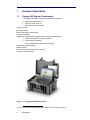
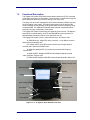
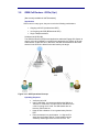
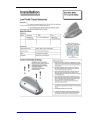
5.4
Appendix 4 - Power Amplifier (Opt.)
Introduction
The purpose of the power amplifier is to extend the effective communication range
between the Engage Gi2 System and the target mobile phones. The power
amplifier enables easy operation of the System from within a car by using a
magnetic base car antenna or external directional antenna.
The Unit can be used with one of 3 types of antennas or a combination thereof:
5.4.1
I.
The Internal Antennas enclosed within the Engage Gi2 System itself
II.
External Passive Antennas
III.
External Power Amplifier
PA Operating Instructions
a. Ensure the Manager is in Standby and not Transmitting
b. The main unit has embedded flat panel directional antennas – an antenna for
each of the frequency bands that your Engage Gi2 System can broadcast on is
configured for transmission and reception.
c. External Passive antennas can be connected to both the Rx and Tx ports of
your Engage Gi2 System in order to improve the reception and transmission
range.
In the case that you want to connect Passive Antennas it is necessary to
unscrew the connectors used by the Antennas in the lid of the Unit.
d. When using the External Power Amplifier caution must be taken to ensure that
the correct connections are established between the System and the PA.
Labels are added to each Unit to indicate which ports are to be used to connect
to the PA.
e. It is recommended to connect the PA in the following manner.
Identify the Tx port, on the Engage Gi2 System, for a particular Band, e.g. 900
Tx, connect this port to the Rf Input port of the same Band on the PA. Repeat
this for process for each Band for which the System and PA are configured.
(Note, you may want to amplify only one particular Band, in which case use
only that particular connection)
f.
Connect the external Antenna to the Rf Output Port of the PA. Repeat this
process for each Band on which you want to have an amplified transmission.
g. If your PA has Rx Inputs then you can connect the Rx Port of the System to the
PA. This can be repeated for each Band.
Note: It is possible and is an accepted configuration that the Tx is amplified
using the PA whilst the Rx uses External Passive Antennas or the Internal
Antennas of the System.
h. Switch on the Main PA switch, if the PA has individual Switches for each Band
then enable the switch for the Band on which you wish to transmit.
Note: the PA Battery life can be prolonged by enabling only the particular band
for which you need to transmit.
i.
The System is now ready to transmit.
Note: ALWAYS go to Standby on the Manager before powering off the PA as
failure to do so may damage the PA.
84
User Manual