1
Micriµm
© Copyright 2004, Micriµm
All Rights reserved
µC/GUI
and the
Soft-Core Processor
AN-5001
www.Micrium.com
µC/GUI
and the Altera Nios II Processor
Table of Contents
1.00
1.01
1.02
1.03
1.04
1.05
1.06
Introduction........................................................................................................... 3
Lancelot VGA Video Controller............................................................................. 4
Using the Lancelot Core ....................................................................................... 5
Adding µC/GUI to your Project ............................................................................. 7
Configuring µC/GUI .............................................................................................. 9
BASIC_HelloWorld.c .......................................................................................... 12
A µC/GUI Demo ................................................................................................. 13
Licensing ............................................................................................................ 14
Contacts ............................................................................................................. 14
2
µC/GUI
and the Altera Nios II Processor
1.00
Introduction
µC/GUI provides graphics software, written in 100% ANSI-“C”, that can be used to add a graphical user
interface to your Nios II application. µC/GUI can be used with a single-task application or with multi-task
applications involving either a proprietary operating system or a commercial RTOS, such as µC/OS-II.
The features available on µC/GUI include the following:
General
• A clear structure
• The display size is configurable.
• Characters and bitmaps may be written at any point on the LCD, not just on even-numbered byte
addresses.
• Routines are optimized for both size and speed.
• Complile time switches allow for different optimizations.
• Virtual display support; the virtual display can be larger than the actual display
Graphic Library
• Bitmaps of different color depths are supported.
• A bitmap converter is available.
• Absolutely no floating-point usage
• Fast line/point drawing (without floating-point usage)
• Very fast drawing of circles/polygons
• Different drawing modes
Fonts
• A variety of different fonts are shipped with the basic software: 4x6, 6x8, 6x9, 8x8, 8x9, 8x16,
8x17, 8x18, 24x32, and proportional fonts with pixel-heights of 8, 10, 13, 16.
• New fonts can be defined and simply linked in.
• Only the fonts used by the application are actually linked to the resulting executable, so there is
minimum ROM usage.
• Fonts are fully scalable, separately in X and Y.
• A font converter is available; any font available on your host system (i.e. Microsoft Windows) can
be converted.
String/Value Output Routines
• Routines to show values in decimal, binary, or hexadecimal, and in any font
• Routines to edit values in decimal, binary, or hexadecimal, and in any font
Window Manager (WM)
• Complete window management including clipping; overwriting of areas outside a window’s client
area is impossible
• Windows can be moved and resized.
• Callback routines are supported (usage is optional).
• WM uses minimum RAM (app. 20 bytes per window).
Optional Widgets for PC Look and Feel
• Widgets (window objects, also known as controls) are available.
automatically and are simple to use.
PC tools
• Simulation plus viewer
• Bitmap converter
• Font converter
3
They generally operate
µC/GUI
and the Altera Nios II Processor
1.01
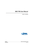
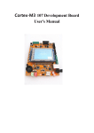
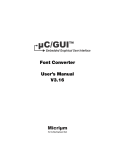
Lancelot VGA Video Controller
µC/GUI can be used on the Altera Nios II Development Boards with the Lancelot VGA video controller.
This peripheral consists of the Lancelot core, which can easily be added to an SOPC Builder-generated
system, along with an add-on daughter board that can be attached to the expansion prototype connectors
on the boards.
Figure 1-1, The Lancelot VGA video controller daughter board.
4
µC/GUI
and the Altera Nios II Processor
1.02
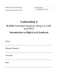
Using the Lancelot Core
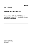
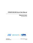
The Lancelot core can be added to a Nios II system in SOPC Builder; simply select the core from the list
of Avalon Modules, as shown in Figure 1-2, below.
Figure 1-2, Adding the Lancelot core to your system.
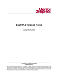
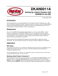
After the core has been added, and it appears in the list of modules included in your system, you must
select the memory device from which the core’s DMA controller will gather video data. In order to specify
a memory device, you should select Show Master Connections from the View menu. This will allow you
to specify which module will serve as a slave device for the core’s DMA controller. Select the desired
device by clicking next to its name under the vga (avalon) column, so that a darkened circle appears.
5
µC/GUI
and the Altera Nios II Processor
Figure 1-3, Selecting a slave device for the Lancelot core’s DMA controller.
After your Nios II system module with the Lancelot core has been generated, you may add the module to
your Quartus II project. You should then assign the Lancelot core’s input and output ports to the
appropriate FPGA pins by consulting the data sheet for your board and the documentation for the
Lancelot controller. If you encounter problems while compliling your Quartus II project, or if you would
like a simple design from which to begin designing graphics software utilizing the Lancelot core,
reference designs for both the Stratix and Cyclone Development Boards are available at www.fpga.nl.
6
µC/GUI
and the Altera Nios II Processor
1.03
Adding µC/GUI to your Project
After your Nios II system has been properly set up with the Lancelot core, beginning to develop with
µC/GUI is simply a matter of copying the appropriate files into your project folder. This section assumes
that you have purchased the µC/GUI package from Micrium (contact Micrium for pricing). µC/GUI is
provided in source code form and is thus compiled along with your application software.
You should place all of the files in three main folders within the project folder; this structure supports a
consistent and easily maintainable environment. Also, since µC/GUI is shipped with this same directory
structure, files can easily be copied from the appropriate µC/GUI folder to the folder within your project
directory with the same name. The three folders that your project should have are:
Application
Config
GUI
This folder holds all of the files associated with your µC/GUI application.
This folder holds the configuration files for µC/GUI.
This is where all of the µC/GUI program files are located.
Because of this directory structure, you will need to specify some additional include search paths that will
be used by the compiler during the build process. Include search paths can be added by right-clicking
your project folder and selecting Properties. You can then select C/C++ Build, and use the New...
button to add paths. Assuming that you have organized your project as described above, the following
paths should be added:
../Config/
../GUI/Core/
../GUI/WM/
../GUI/Widget/
This is where the µC/GUI configuration header files are located.
This folder contains general µC/GUI header files.
This folder contains header files associated with the Window Manager.
This folder contains header files associated with the Widget library.
Once you have created the suggested folders, and added the include search paths, you can begin
copying the µC/GUI files into your project folder. As a minimum, you will need to copy the following files:
•
•
•
All “C” files of the folder GUI\Core
The fonts that you plan to use (in GUI\Font)
The LCD driver: LCDLin32.c (in GUI\LCDDriver)
If you plan to use additional, optional modules you must also copy their “C” files.
•
•
•
•
•
•
Grayscale converting function: all “C” files located in GUI\ConvertMono
Color conversion functions: all “C” files located in GUI\ConvertColor
Antialiasing: all “C” files located in GUI\AntiAlias
Memory devices: all “C” files located in GUI\MemDev
Widget library: all “C” files located in GUI\Widget
Window Manager: all “C” files located in GUI\WM
Additionally you must copy the hardware-dependent file GUI_X.c from Sample\GUI_X to your
Application directory. After all of the files have been copied, your project should resemble Figure 1-4,
below.
7
µC/GUI
and the Altera Nios II Processor
Figure 1-4, Example project folder.
8
µC/GUI
and the Altera Nios II Processor
1.04
Configuring µC/GUI
Configuring µC/GUI basically involves modifying three files: LCDConf.h, GUIConf.h, and GUI_X.c.
GUIConf.h is a high-level configuration file used mainly to enable support for various options, such as
memory devices. It is explained further in the µC/GUI User’s Manual. LCDConf.h and GUI_X.c are
dependent on the hardware, and implementations of these files for the Nios II are described in the
sections that follow.
Listing 1-1, LCDConf.h
#ifndef LCDCONF_H
#define LCDCONF_H
#define LCD_XSIZE
#define LCD_YSIZE
#define
#define
#define
#define
#define
#define
LCD_BITSPERPIXEL
LCD_CONTROLLER
LCD_ENDIAN_BIG
LCD_ALLOW_NON_OPTIMIZED_MODE
LCD_FIXEDPALETTE
LCD_SWAP_RB
800
600
// (1)
8
3200
0
1
8666
1
// (2)
#define LCD_VRAM_ADR DispRam
// (3)
#define LCD_SET_LUT_ENTRY(Pos, Color)\
// (4)
IOWR_LANCELOT_VGA_COLOUR(VGA_BASE, ((((U32)Pos) << 24) | (0x00FFFFFF & Color)))
#define LCD_READ_MEM(Off)
#define LCD_WRITE_MEM(Off,data)
(*((U32 *)DisplayRam + (U32)Off))
*((U32 *)DisplayRam + (U32)Off) = data
// (5)
#define LCD_INIT_CONTROLLER()\
// (6)
DispRam = (U32*) alt_uncached_malloc(800*600);\
IOWR_LANCELOT_VGA_RESET(VGA_BASE, 0x12345678);\
while((IORD_LANCELOT_VGA_STATUS(VGA_BASE) & 0xFFFF0000) != 0x52470000);\
IOWR_LANCELOT_VGA_RESOLUTION(VGA_BASE, (HORIZONTAL_RESOLUTION << 16) + VERTICAL_RESOLUTION);\
IOWR_LANCELOT_VGA_HORIZONTAL(VGA_BASE, (HSYNC_PULSE_WIDTH << 16)\
+ (HSYNC_BACK_PORCH_WIDTH << 8)\
+ HSYNC_FRONT_PORCH_WIDTH);\
IOWR_LANCELOT_VGA_VERTICAL(VGA_BASE, (VSYNC_PULSE_WIDTH << 16) + (VSYNC_BACK_PORCH_WIDTH << 8)\
+ VSYNC_FRONT_PORCH_WIDTH);\
IOWR_LANCELOT_VGA_CONTROL(VGA_BASE, LANCELOT_VGA_CONTROL_START_VIDEO\
| LANCELOT_VGA_CONTROL_SET_DAC);\
IOWR_LANCELOT_VGA_DMA(VGA_BASE, (U32) (DispRam) & 0x7FFFFFFF)
#endif
L1-1(1)
The resolution is set to 800 x 600. The Lancelot VGA video controller also supports
resolutions of 640 x 480 and 1024 x 768.
L1-1(2)
Several definitions are needed to specify the video controller and the color palette that will be
used. Setting LCD_CONTROLLER to 3200 selects the LCDLin32.c driver, which is
compatible with the Lancelot controller. LCD_FIXEDPALETTE is set to 8666, but this is not
the only palette that can be used with the Lancelot controller. For descriptions of additional
palettes, see the µC/GUI User’s Manual.
9
µC/GUI
and the Altera Nios II Processor
L1-1(3)
LCD_VRAM_ADR indicates the address where video memory begins. Since the Lancelot
video controller does not include its own video memory, this address will actually be in the
memory device that is designated to hold read/write data in the project’s System Library
Properties. This should be the same device that was selected as a slave device for the
video controller in SOPC Builder.
L1-1(4)
LCD_SET_LUT_ENTRY() is used by µC/GUI to set entries in the Lancelot video controller’s
color table. Entries in the color table are modified with IOWR_LANCELOT_VGA_COLOUR(),
which is defined in the file lancelot_vga_regs.h that is included with the Lancelot
component.
L1-1(5)
LCD_READ_MEM() and LCD_WRITE_MEM() specify how to read to and write from the video
memory.
L1-1(6)
LCD_INIT_CONTROLLER() prepares the video controller to begin reading video data. This
routine actually allocates the space that will be used for video memory. The routine also sets
up the resolution and timing registers on the Lancelot video controller. The documentation
for the controller describes appropriate values for constants like HORIZONTAL_RESOLUTION
and VSYNC_PULSE_WIDTH.
Listing 1-2, GUI_X.c
#include “includes.h”
// (1)
volatile int OS_TimeMS;
int
{
GUI_X_GetTime (void)
// (2)
int ticks;
ticks
= OSTimeGet();
OS_TimeMS = ticks;
return (ticks);
}
void
{
GUI_X_Delay (int ms)
// (3)
ms = ms * 10;
OSTimeDlyHMSM(0,0,0,ms);
}
L1-2(1)
includes.h is a master include file that is usually used in µC/OS-II applications. It should
include any files needed by your application. For µC/GUI applications, includes.h should
include GUI.h. If you are not using µC/OS-II, or if you choose not to place GUI.h in
includes.h, you must manually include GUI.h in all of your application files.
L1-2(2)
GUI_X_GetTime() uses the µC/OS-II function OSTimeGet() to return the time expressed
in “ticks”. If µC/OS-II is not being used, this function needs to be modified.
L1-2(3)
GUI_X_Delay() uses the µC/OS-II function OSTimeDlyHMSM() to delay the task from
which uC/GUI functions are called. Again, if µC/OS-II is not used, this function will have to be
rewritten.
10
µC/GUI
and the Altera Nios II Processor
In addition to the two functions declared in Listing 1-2, the functions shown below need to be declared in
GUI_X.c (but they can be left empty).
void
void
void
void
void
GUI_X_Init (void)
GUI_X_ExecIdle (void)
GUI_X_Log (const char *s)
GUI_X_Warn (const char *s)
GUI_X_ErrorOut (const char *s)
These empty functions, along with the two functions described above, should be all that is required for an
application running µC/OS-II and calling µC/GUI functions from only one task (GUI_OS is 0). If you are
not running µC/OS-II, or if you wish to call µC/GUI functions from multiple tasks, GUI_X.c will need to be
modified. The µC/GUI User’s Manual contains further information about modifying GUI_X.c.
11
µC/GUI
and the Altera Nios II Processor
1.05
BASIC_HelloWorld.c
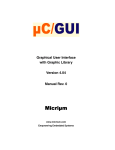
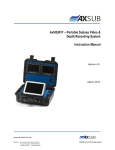
BASIC_HelloWorld.c, which comes with µC/GUI, is a simple example program that can be used to
make sure you have configured everything properly. In a multi-task environment, copy MainTask()
from the file and add it to your application. In a single-task environment change the name of
MainTask() and place it into your application as main(). You can then build and run your project. The
video controller should display a screen similar to that shown below.
Figure 1-5, BASIC_HelloWorld.c.
12
µC/GUI
and the Altera Nios II Processor
1.06
A µC/GUI Demo
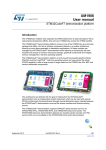
ucgui.flash is a flash file that can be programmed onto your Nios development board, Stratix edition
so that you can view a running demo of many of µC/GUI’s features. In order to view the demo, you
should first use the nios2-flash-programmer utility to program gui_system.flash to flash memory on
your board. The nios2-flash-programmer must be run from the Nios II SDK shell. You will need to
specify an input file (gui_system.flash), the flash base address (which should be 0x00800000) and
a .sof file, which is the flash programmer design that will be configured on the FPGA. The flash
programmer design is included with your development board, and can be found in a standard location.
For example, the flash programmer design for the Stratix EP1S10ES Nios development board can be
found in the following location:
<nios2kitinstall>/components/altera_nios_dev_board_stratix_1s10_es/system
gui_system.flash contains the FPGA configuration data for the hardware that the demo will run on.
After it has been programmed into flash memory, ucgui.flash can be programmed using the
nios2-flash-programmer as described above. The board’s Reset Config button should then be
pressed, after which a screen similar to that shown in Figure 1-6 should appear. Subsequent screens will
display additional examples of µC/GUI’s capabilities.
Figure 1-6, µC/GUI demo title screen.
13
µC/GUI
and the Altera Nios II Processor
Licensing
µC/GUI is licensed on a per end-product basis. Specifically, each different product that embeds µC/GUI
in a commercial product requires a different license. A license allows you to manufacture an unlimited
number of units of the product that embeds µC/GUI for the life of that product. In other words, a µC/GUI
license is royalty free. Contact Micrium for pricing information.
Contacts
Micriµm
949 Crestview Circle
Weston, FL 33327
USA
+1 954 217 2036
+1 954 217 2037 (FAX)
e-mail: [email protected]
WEB: www.Micrium.com
14