1
April 2005
170-765-00A
EPX
2
EPX
2
Explosion Proof Voltage-to-Pressure
(E/P) Transmitter
Explosion Proof Voltage-to-Pressure
(E/P) Transmitter
All product names are registered trademarks of their respective companies.
Table of Contents
Introduction ....................................................................................................... 3
The EPX2 ............................................................................................................ 3
Specifications ................................................................................................... 3
Calibration ......................................................................................................... 4
Necessary Equipment .........................................................................................................4
Preparing for Calibration .....................................................................................................4
Calibration Process ............................................................................................................ 5
Installation ......................................................................................................... 7
Phase One: Mounting ......................................................................................................... 7
Phase Two: Electrical Connections .................................................................................... 7
Phase Three: Pneumatic Connections ...............................................................................8
Operation ........................................................................................................... 9
Maintenance ...................................................................................................... 9
Troubleshooting the EPX2 .................................................................................................................................... 10
Customer Service ........................................................................................... 10
EPX 2
Explosion Proof Voltage-to-Pressure
(E/P) Transmitter
Introduction
EPX2
This is the user’s manual for the Moore Industries
Voltage-to-Pressure Transmitter (EPX2). It contains
all of the information that is needed to calibrate,
install, operate, maintain and troubleshoot the
instrument.
The rugged EPX2 Voltage-to-Pressure (E/P) Transmitters are designed specifically for extended duty in harsh
field environments. The extruded aluminum housing of
the EPX2 is explosion-proof and waterproof, making it
perfect for most any location.
The following guidelines are used in this manual:
WARNING - Hazardous procedure or condition that
could injure the operator.
Caution - Hazardous procedure or condition that could
damage or destroy the unit.
Note - Information that is helpful for a procedure,
condition or operation of the unit.
This 3-wire (auxiliary-powered) transmitter converts a
voltage signal to a pneumatic actuator, valve or damper
drive. This instrument accepts a 3-wire (1-5Vdc, 20100kPA, etc.) input.
Units are available with an optional coalescing filter/
regulator that combines an air filter and miniature
supply line regulator with a pressure gauge that reads in
both psi and bars.
Specifications
Performance Accuracy: <±0.25% of
span including the combined
effect of linearity, hysteresis
and repeatability (between
0 and 3psig output, error will
not exceed ±1.0% of span)
Input: 1-5 Volts
Voltage Input Impedence:
1 Mohm
Output: 3-15psig;
0-30psig; 6-30psig
Stability: Not to degrade
from stated accuracy for six
months
Step Response: <0.2
seconds into 100ml load
(6 in3) from 10% to 90% of
span; Not guaranteed below
3psig output.
Supply Pressure Effect:
Negligible from 20-40psig,
steady pressure
Air Capacity:
5.0SCFM minimum (20psig
supply, 0psig output)
Relief Capacity: 2.5SCFM
minimum (15psig output)
Air Supply: Instrument air
only, 20-40psig (Must be
5psig greater than maximum
output)
Gas Supply with –NG1 or
Performance –NG2 Options: Same
(Continued) cleanliness as instrument air.
H2S not to exceed 20ppm
Air Consumption
(Dead-ended):
At 3psig output, 20psig
supply, consumes
0.08SCFM (0.14m3/hr),
maximum; At 15psig output,
20psig supply, consumes
0.10SCFM (0.17m3/hr),
maximum; At 15psig output,
40psig supply, consumes
0.15SCFM (0.26m3/hr),
maximum; At 30psig output,
40psig supply, consumes
0.17SCFM (0.29m3/hr),
maximum
Maximum Input: 80psig
without damage for units with
output pressure rating of
>15psig; 45psig without
damage for units with output
pressure rating of >15psig
Power Supply:
9-30Vdc, 5mA maxiumum
Mounting Position Effect:
Negligible, unit can be
mounted in any position;
Should be mounted upright or
horizontal to keep water out if
it is not in a dry environment
Ambient Operating & Storage
Conditions Range:
-40°C to +85°C
(-40°F to +185°F)
Ambient Temperature
Effect: <±0.025% of
span/°C, maximum from
-20°C to 80°C; <±0.1% of
span/°C, maximum
RFI/EMI Effect:
<±0.1% of span change in
field strengths of 10V/m @
frequencies of 20-500MHz
Shock and Vibration
Effect: Meets
SAMA PMC 31.1 as detailed
in the field mounted category
Relative Humidity:
0-100%, non-condensing
Adjustment Zero & Span: Screw
adjusts zero or span by
±10% minimum,
non-interactive
Weight 2.0kg (4.4 lbs)
Specifications and information subject to change without notice.
The Interface Solution Experts
3
EPX 2
Explosion Proof Voltage-to-Pressure
(E/P) Transmitter
Preparing for Calibration
Calibration
Every EPX2 is fully tested and calibrated at the factory
prior to shipment. However, before installation, your
instrument should be bench-checked to verify the
desired unit zero and unit span. Calibration should be
conducted in an appropriate testing environment.
Necessary Equipment
Table 1 lists the equipment required to calibrate the
unit. This equipment is not supplied by Moore Industries, but should be available in most labs or maintenance areas.
Table 1. EPX 2 Calibration Equipment
Equipment
Description
Adjustable voltage source
0-10 Volts
Voltage Power Source
8-30Vdc
DC Multimeter
Accurate to ±0.05%
Instrument air supply
Filtered
Air pressure gauge #1
Accurate to ±2%
Air pressure gauge #2
Accurate to ±0.1%
Pneumatic load
Volume of 7.5 cubic inches
(approximately 120 milliliters)
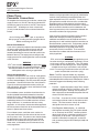
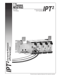
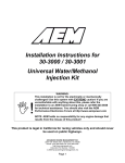
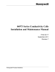
To prepare the EPX2 for calibration, remove the screwon cap and connect the unit to your configuration
equipment as shown in Figure 1.
Unit Connections and Controls. The EPX2 3-wire
units are connected to the conduit and wire inside the
unit.
The two controls are also located inside the unit
housing under the screw-on cap. They consist of two
potentiometers, each accessed through the front panel.
They are labeled “zero” and “span”. The zero potentiometer provides a control range for offsets of ±10% of
rated unit span, while the span potentiometer adjusts
unit full-scale output to 100 percent of rated span.
To adjust the potentiometer move its wiper from one
extreme to the other: clockwise for maximum, or
counterclockwise for minimum values. Each is
equipped with a slip clutch to prevent damage if the
adjustment is turned beyond the wiper stop.
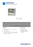
Figure 1. EPX 2 Hook-Up Diagram
WITHOUT
-NG1 OR -NG2 OPTION
+DC
9-30VDC
POWER
SUPPLY
–DCC
WITH
-NG1 OR -NG2 OPTION
RED
9-30VDC
POWER
SUPPLY
+IN
VOLTAGE
INPUT
SIGNAL
-IN
VOLTAGE
INPUT
SIGNAL
+DC
BLACK
–DCC
WHITE
+IN
BLACK
-IN
NOTE: DCC and –IN ARE COMMON (CONNECTED INTERNALLY).
4
The Interface Solution Experts
EPX 2
Explosion Proof Voltage-to-Pressure
(E/P) Transmitter
Note:
Always use clean, dry, instrument air when
calibrating or operating the EPX 2.
All pneumatic lines used in calibration and operation
must be purged prior to connection to the unit. Any
condensation or oil residue in the lines, if introduced
into the pneumatic chambers of the unit, may result in
poor unit performance.
Calibration Process
To perform the recommended bench-check for the
EPX2, first perform the setup as described in the next
section. See Figure 1 for illustration of the Calibration
Setup, then follow the steps under Calibration Setup
and Calibrating the EPX2.
Calibration Setup
1. Connect 1/4-inch pneumatic tubing between the
appropriate output port of the regulated instrument
air supply and the pressure gauge #1 (accuracy of
±2% of span). Connect another tube from the
pressure gauge to the port labeled “IN” on the
EPX2.
2. Connect 1/4-inch pneumatic tubing between the
port labeled “OUT” and the appropriate port of
pressure gauge #2 (accuracy of ±0.1% of span),
then from gauge #2 to the appropriate pneumatic
load.
Calibrating the EPX2
This calibration procedure consists of a basic check
and adjustment of unit zero and span, based on the
reading of pressure gauge #2. To calibrate, perform the
following:
1. Check unit zero setting. Monitor reading of pressure gauge #2 (output), and turn zero potentiometer
counterclockwise to lower output, clockwise to
raise output. Set zero potentiometer so that
pressure output is at 0% of span when a current
input of 0% of span is applied (i.e. 3psi for a
3-15psi unit).
2. Check unit span setting. Increase input to 100% of
rated span (i.e. 5Vdc).
3. Monitor reading of pressure gauge #2 (output), and
adjust span potentiometer so that reading is at
100% of span for your unit (i.e. 15psi for a 3-15psi
unit).
4. Repeat steps 1 through 3 until the unit outputs 0%
of rated pressure range at 0% current input, and
100% of output pressure range at 100% of span.
5. Verify the accuracy of your adjustments by
inputting 0%, 25%, 50%, and 75% of span inputs,
and monitoring the output.
3. Run voltage source wiring through conduit opening
in housing.
4. Connect the positive lead of your adjustable voltage
source (white wire) to the +IN terminal of the unit.
Connect the negative input source lead (black wire)
to the –IN terminal. Connect the positive lead of
the power source (red wire) to the +DC, and the
negative lead of the power source (black wire) to
the DCC . A multimeter may also be connected to
verify level of voltage input.
5. When connections are complete, apply an input
voltage of 0% of span (i.e. 1Vdc).
6. Apply appropriate filtered, instrument-quality air to
supply line: 20 or 35psi (1.4bar to 2.4bar). Verify
appropriate supply pressure by checking Supply
Pressure field of unit model number.
7. Allow approximately 30 seconds for calibration
setup to stabilize.
The Interface Solution Experts
5
EPX 2
Explosion Proof Voltage-to-Pressure
(E/P) Transmitter
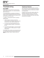
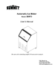
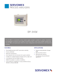
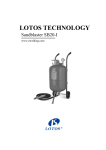
Figure 2. EPX 2 Voltage-to-Pressure Transmitter Housing Dimensions
TOP VIEW
(WITH PIPE CLAMP)
125mm
(4.9 in)
89mm
(3.5 in)
MANUAL OVERRIDE &
FILTER HOLDER
MANUAL OVERRIDE &
FILTER HOLDER
SIDE VIEW
(–NG OPTION)
BACK VIEW
(NO OPTIONS)
FRONT VIEW
(NO OPTIONS)
154mm
(6.1 in)
INSTRUMENT
TAG
1/4 NPT FEMALE
PNEUMATIC
INPUT PORT
BOTTOM VIEW
(–NG OPTION)
BOTTOM VIEW
(NO OPTIONS)
1/4 NPT FEMALE
PNEUMATIC
OUTPUT PORT
1/2 NPT
OUTPUT
VENT
102mm
(4.0 in)
25mm
(1.0 in)
125mm
(4.9 in)
NATURAL GAS VENT
(–NG1 OPTION SHOWN)
FRONT VIEW
(WITH –NG OPTION)
NOTE:
BOTH SIDE FITTINGS ARE
PERMANENTLY ATTACHED.
DO NOT ATTEMPT TO REMOVE.
(THEY MAY BE INSTALLED ON
EITHER SIDE OF THE UNIT BY
THE FACTORY)
PERMANENT
FITTING
INSTRUMENT
TAG
166mm
(6.5 in)
6
The Interface Solution Experts
NOTE:
–NG1 MODEL SHOWN.
FOR THE –NG2, THE
ELECTRICAL CONDUIT
IS ON THE RIGHT SIDE,
AND PERMANENT PLUG
IS ON THE LEFT.
EPX 2
Explosion Proof Voltage-to-Pressure
(E/P) Transmitter
Installation
The installation of the EPX2 is carried out in three
phases: the physical mounting of the unit, the electrical
connections phase and the pneumatic connections
phase. It is strongly suggested that each unit be
calibrated according to the instructions in this manual
before being placed into service.
Phase One: Mounting
Figure 2 gives the dimensions of the EPX2. The
illustrations also give the dimensions of the available
option hardware, which is recommended for most
installations. After placing the unit in the desired
location and orientation, secure the housing with the
optional pipe mounting hardware or other appropriate
fasteners.
2
The EPX may be installed at any angle–either surfacemounted or attached to pipe or round conduit. However, if water entering the unit is a consideration the
EPX2 should be mounted with at least one vent on a
low side. The EPX2 with natural gas (–NG1 or
–NG2) option does not have an open vent, so water is
not a consideration.
Phase Two: Electrical Connections
Connect the positive lead of your adjustable voltage
source (white wire) to the +IN terminal of the unit.
Connect the negative input source lead (black wire) to
the –IN terminal. Connect the positive lead of the
power source (red wire) to the +DC, and the negative
lead of the power source (black wire) to the DCC . A
multimeter may also be connected to verify level of
voltage input..
• Any Moore Industries product in a metal
case or housing should be grounded.
• The protective earth conductor must be
connected to a system safety earth ground
before making any other connections.
• All input signals to, and output signals
from, Moore Industries’ products should be
wired using a shielded, twisted pair
technique. Shields are to be connected to an
earth or safety ground at the unit itself.
Ground only one end of the shield.
• The maximum length of unshielded input
and output signal wiring should be 2-inches.
Power Sourcing Parameters for General
Locations, Intrinsically Safe, and
Non-Incendive/Type N applications
In accordance with IEC 1010.1 Annexes F.2.1 and H
(all models) or any equivalent international standard,
the input terminals must be connected to and/or
supplied from a certified energy limiting Class 2 or a
Separated Extra Low Voltage (S.E.L.V.) power supply
separated from all mains by double/reinforced
insulation.
Caution:
When connecting the EPX 2 Natural Gas (–NG1 or
–NG2) model, use an appropriately certified conduit box
and wire connectors. Do not attempt to remove the
seal fitting. For input source, connect the positive lead
(+) to the white wire from the seal fitting, and the
negative lead (–) to the black wire from the seal fitting.
Note:
+Power is connected to the DC red wire.
–Power is connected to the DCC black wire.
Use shielded, twisted-pair wiring for low-level input.
Ground the shielding wire as close as possible to the
installed unit.
Recommended Ground Wiring Practices
Moore Industries recommends the following ground
wiring practices:
The Interface Solution Experts
7
EPX 2
Explosion Proof Voltage-to-Pressure
(E/P) Transmitter
Phase Three:
Pneumatic Connections
To complete the final phase of installation, connect the
supply line to the ¼-inch NPT female port labeled “IN”.
Connect the output line to the ¼-inch NPT female port
labeled “OUT”. All tubing must have at least 6mm
(¼-inch) inside diameter or the maximum flow will be
limited.
Note:
Seal all fittings with Teflon® tape, or equivalent.
Always purge all tubing and the controlled device
before connecting the EPX2.
Manual Override Screw
If you are in a potentially explosive environment and do
not want to apply electric power to the unit with the
cover removed, the pneumatic installation may be
tested by loosening the manual override screw on the
bottom of the unit. The output pressure will go to the
supply pressure. Be sure to tighten the manual override
screw after test.
WARNING:
EPX 2 units installed in a natural gas application must
have the natural gas vent properly connected. Follow
the directions below to install an EPX 2 with –NG1 or
–NG2 options into a natural gas application.
Natural Gas Applications
Customers using the EPX2 with –NG1 or –NG2 options
to regulate a sweet natural gas application (H2S levels
are not to exceed 20ppm) must also make the vent port
connections. Connect the Natural Gas Vent (shown in
Figure 2) to a device prepared to receive natural gas.
After connection, the fittings, cover and filter/test screw
should be tested for leaks.
For an outdoor system, ventilation should consist of a
weather-proofed connection between the transmitter
exhaust and a riser, six feet above the transmitter and
control valve assembly. The riser should be shepherdcrooked to prevent rain or incident water from accumulating at the base. In accordance with local safety
regulation, an in-line flame arrestor should be applied to
the riser to prevent flash back to the transmitter from an
external, spontaneous flame source.
For an indoor system, ventilation must consist of a
leak-proof connection from the exhaust of the transmitter to a process vent. The process vent should already
be dedicated for natural gas excursions and should
conform to all standards for flaring or after-burn, and
flame arrest, as dictated by local environmental and
safety regulations.
8
The Interface Solution Experts
Indoor natural gas operations are typically monitored to
maintain safety conformance outside the lower and
upper explosion limits (LEL and UEL). To add a natural
gas operated transmitter in these cases, consideration
should be made as to the extent of natural gas leak
detection legacy to the installed transmitter. Placement
of the transmitter should be such that detection and
alarming surround any critical connections between the
transmitter and the natural gas process.
If the natural gas driven transmitter is to be installed
indoors with no legacy monitoring capabilities,
additional consideration must be made to ensure the
operating area is well-ventilated and the transmitter can
be exhausted to a process vent. Furthermore, monitoring with remote annunciation within LEL and UEL
should be projected as an upgrade to the facility,
concurrently with this installation. The transmitter
installation must adhere to local environmental and
safety regulations.
WARNING:
EPX 2 units installed in a natural gas application must
have the natural gas vent properly connected. Failure
to do so may result in an explosion. The –FR1 option
is not suitable for flammable gas use. A filter-regulator
suitable for natural gas use without a vent may be
used. For natural gas certification to be valid, the vent
system must be able to maintain <1psig.
Filters. The EPX2 requires filtered, dry, regulated,
instrument-quality air to prevent clogging and to ensure
extended periods of maintenance-free operation. Moore
Industries suggests the following levels of filtering
protection:
•
Pre-filter – A general purpose “rough” filter, used to
reduce particulate matter to 5 microns in size. Also
removes bulk liquids. Although not required, this
filter is especially recommended to protect the 0.01
micron final filter when used.
•
Final Filter – A second, final filter is recommended
to remove particulate matter in sizes down to 0.01
micron. This filter removes virtually all condensable liquids from the air stream as well.
•
Filter/Regulator Module Option – A combined
filter/regulator assembly, the -FR1 Option, offered
as an accessory for the EPX2, removes particles
down to 0.01 microns, supplying regulated, instrument-quality air to the unit. This space-saving
module is affixed to the supply port, and comes
with a pressure gauge scaled in both psi (0-60) and
bars (0-4).
EPX 2
Explosion Proof Voltage-to-Pressure
(E/P) Transmitter
Operation
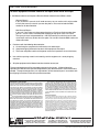
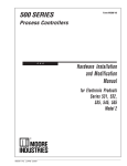
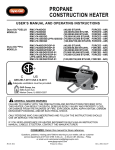
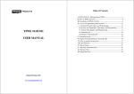
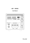
Figure 3. Filter Replacement Diagram
Once the unit has been configured and installed, it
operates unattended with the exception of the minor
maintenance procedures that are described in the next
section.
EPX 2
BOTTOM
If the unit is determined to be the cause of a loop
irregularity, carry out the maintenance procedure in the
next section of this manual. If problems persist, refer
to the Troubleshooting section.
Instrument-quality Air. Air from the application
continuously flows through the EPX2 during operation.
Depending upon the purity of the air supply, the unit’s
internal assembly may have to be removed and cleaned
to ensure continued optimum performance.
Initially, random checks can help establish a satisfactory internal maintenance geared to the user’s air
supply cleanliness. Refer to the next section for
instruction on the disassembly and cleaning of your
unit.
O-RING
P/N 802-187-24
ORIFICE
ASSEMBLY
FILTER
P/N 800-829-43
O-RING
P/N 802-186-24
SPRING (IF LOST)
P/N 800-011-24
Maintenance
For most applications, no maintenance outside of
routine inspection and calibration of the EPX2 will be
necessary. These units are designed to work unattended for up to six months with little change in accuracy.
Occasionally, a unit will become clogged when its air
source becomes contaminated. An internal filter will
prevent the control orifice and nozzle from being
clogged. To replace the filter, you will need to order the
filter and two (for EPX2) or three (EPX2 –NG1 or –NG2)
o-rings from Moore Industries, (see Figure 3 for part
numbers) then follow the instructions below. This filter
is not intended to replace any of the filters described in
the Installation section.
Use a screwdriver to remove the filter holder from the
bottom of the unit. Remove the orifice assembly and
filter from the filter holder, taking care not to lose any of
the parts. Replace the filter and o-rings in the filter
holder. Screw the filter holder back into place. If this is
an EPX2 unit with –NG1 or –NG2 options and is being
used in a natural gas application, you will also want to
test for natural gas leaks at this time.
FILTER
HOLDER
O-RING
(EPX2 –NG) P/N 802-198-24
Note:
After maintenance, the EPX 2 should be recalibrated
before it is returned to service. Refer
to the Calibration section of this manual
for instructions.
Drain Check. System filters (not EPX2 filters) have
automatic drains that depend on the fluctuation of
system pressure to induce drainage. A stable system
may not drain efficiently. Check periodically for clogs
and drain system’s filters by pushing the drainage valve
with a small probe or wire.
The Interface Solution Experts
9
EPX 2
Explosion Proof Voltage-to-Pressure
(E/P) Transmitter
Troubleshooting
the EPX2
Many components of the EPX2 have been thermally
aged, tested and selected. This usually makes field
repair unnecessary.
It is recommended that any properly maintained unit
found to be performing below specifications be returned
to the factory in accordance with the instructions found
on the back cover of this manual.
If a problem is suspected with the EPX2, review the
following steps:
1. Verify that bench instruments used to take
measurements have the proper range and accuracy
and are within current certification period limits.
2. If a change in the relationship between the input
and output is detected, attempt a re-calibration of
the unit.
3. If the response time lengthens, or if the span drops,
check the system for a blockage due to air supply
contamination.
The complete valve assembly can be removed from the
housing for replacement without disturbing the connections to the housing. Contact customer service for
details.
10
The Interface Solution Experts
Customer Service
If service assistance is ever required for your EPX2,
refer to the back cover of this manual for the telephone
numbers to Moore Industries’ STAR Center customer
service department.
If possible, make a note of the model number of the
offending module before calling. For the fastest
assistance, try to gather information on the unit(s)
serial number and the job and purchase order number
under which it was shipped.
RETURN PROCEDURES
To return equipment to Moore Industries for repair, follow these four steps:
1. Call Moore Industries and request a Returned Material Authorization (RMA) number.
Warranty Repair –
If you are unsure if your unit is still under warranty, we can use the unit’s serial number
to verify the warranty status for you over the phone. Be sure to include the RMA
number on all documentation.
Non-Warranty Repair –
If your unit is out of warranty, be prepared to give us a Purchase Order number when
you call. In most cases, we will be able to quote you the repair costs at that time.
The repair price you are quoted will be a “Not To Exceed” price, which means that the
actual repair costs may be less than the quote. Be sure to include the RMA number on
all documentation.
2. Provide us with the following documentation:
a) A note listing the symptoms that indicate the unit needs repair
b) Complete shipping information for return of the equipment after repair
c) The name and phone number of the person to contact if questions arise at the factory
3. Use sufficient packing material and carefully pack the equipment in a sturdy shipping
container.
4. Ship the equipment to the Moore Industries location nearest you.
The returned equipment will be inspected and tested at the factory. A Moore Industries
representative will contact the person designated on your documentation if more information is
needed. The repaired equipment, or its replacement, will be returned to you in accordance with
the shipping instructions furnished in your documentation.
WARRANTY DISCLAIMER
THE COMPANY MAKES NO EXPRESS, IMPLIED OR STATUTORY WARRANTIES (INCLUDING ANY WARRANTY OF MERCHANTABILITY OR OF FITNESS
FOR A PARTICULAR PURPOSE) WITH RESPECT TO ANY GOODS OR SERVICES SOLD BY THE COMPANY. THE COMPANY DISCLAIMS ALL WARRANTIES ARISING FROM ANY COURSE OF DEALING OR TRADE USAGE, AND
ANY BUYER OF GOODS OR SERVICES FROM THE COMPANY ACKNOWLEDGES THAT THERE ARE NO WARRANTIES IMPLIED BY CUSTOM OR
USAGE IN THE TRADE OF THE BUYER AND OF THE COMPANY, AND THAT
ANY PRIOR DEALINGS OF THE BUYER WITH THE COMPANY DO NOT IMPLY THAT THE COMPANY WARRANTS THE GOODS OR SERVICES IN ANY
WAY.
ANY BUYER OF GOODS OR SERVICES FROM THE COMPANY AGREES
WITH THE COMPANY THAT THE SOLE AND EXCLUSIVE REMEDIES FOR
BREACH OF ANY WARRANTY CONCERNING THE GOODS OR SERVICES
SHALL BE FOR THE COMPANY, AT ITS OPTION, TO REPAIR OR REPLACE
THE GOODS OR SERVICES OR REFUND THE PURCHASE PRICE. THE
COMPANY SHALL IN NO EVENT BE LIABLE FOR ANY CONSEQUENTIAL OR
INCIDENTAL DAMAGES EVEN IF THE COMPANY FAILS IN ANY ATTEMPT
TO REMEDY DEFECTS IN THE GOODS OR SERVICES , BUT IN SUCH CASE
THE BUYER SHALL BE ENTITLED TO NO MORE THAN A REFUND OF ALL
MONIES PAID TO THE COMPANY BY THE BUYER FOR PURCHASE OF THE
GOODS OR SERVICES.
ANY CAUSE OF ACTION FOR BREACH OF ANY WARRANTY BY THE
COMPANY SHALL BE BARRED UNLESS THE COMPANY RECEIVES
FROM THE BUYER A WRITTEN NOTICE OF THE ALLEGED DEFECT OR
BREACH WITHIN TEN DAYS FROM THE EARLIEST DATE ON WHICH THE
BUYER COULD REASONABLY HAVE DISCOVERED THE ALLEGED DEFECT OR BREACH, AND NO ACTION FOR THE BREACH OF ANY WARRANTY SHALL BE COMMENCED BY THE BUYER ANY LATER THAN
TWELVE MONTHS FROM THE EARLIEST DATE ON WHICH THE BUYER
COULD REASONABLY HAVE DISCOVERED THE ALLEGED DEFECT OR
BREACH.
RETURN POLICY
For a period of thirty-six (36) months from the date of shipment, and under
normal conditions of use and service, Moore Industries ("The Company") will
at its option replace, repair or refund the purchase price for any of its manufactured products found, upon return to the Company (transportation charges
prepaid and otherwise in accordance with the return procedures established
by The Company), to be defective in material or workmanship. This policy
extends to the original Buyer only and not to Buyer's customers or the users
of Buyer's products, unless Buyer is an engineering contractor in which case
the policy shall extend to Buyer's immediate customer only. This policy shall
not apply if the product has been subject to alteration, misuse, accident, neglect or improper application, installation, or operation. THE COMPANY
SHALL IN NO EVENT BE LIABLE FOR ANY INCIDENTAL OR CONSEQUENTIAL DAMAGES.
United States • [email protected]
Tel: (818) 894-7111 • FAX: (818) 891-2816
Australia • [email protected]
Tel: (02) 8536-7200 • FAX: (02) 9525-7296
© 2005 Moore Industries-International, Inc.
Belgium • [email protected]
Tel: 03/448.10.18 • FAX: 03/440.17.97
The Netherlands • [email protected]
Tel: (0)344-617971 • FAX: (0)344-615920
China • [email protected]
Tel: 86-21-62491499 • FAX: 86-21-62490635
United Kingdom • [email protected]
Tel: 01293 514488 • FAX: 01293 536852
Specifications and Information subject to change without notice.
User’s Manual Supplement
EPX2
Natural Gas Applications
June 2007
The information contained within this document accompanies the EPX2 User’s Manual, 170-765-00A.
When using the –NG1 and –NG2 options for natural gas
applications, ensure that the electrical conduit is sealed
within 18 inches of the EPX2 in order to prevent gas from
leaking into the conduit.
United States • [email protected]
Tel: (818) 894-7111 • FAX: (818) 891-2816
Australia • [email protected]
Tel: (02) 8536-7200 • FAX: (02) 9525-7296
© 2007 Moore Industries-International, Inc.
170-765-01A
Belgium • [email protected]
Tel: 03/448.10.18 • FAX: 03/440.17.97
The Netherlands • [email protected]
Tel: (0)344-617971 • FAX: (0)344-615920
China • [email protected]
Tel: 86-21-62491499 • FAX: 86-21-62490635
United Kingdom • [email protected]
Tel: 01293 514488 • FAX: 01293 536852
Specifications and information subject to change without notice.