1
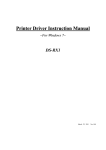
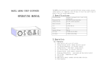
Table of Contents
TPMS 10.02.011
USER MANUAL
Impaqed Products BV
www.impaqedproducts.eu
I. TPMS 10.02.011, Full-time Direct TPMS----------------------------------3
II. Parts of TPMS 10.02.011-----------------------------------------------------4
III. Installation of TPMS 10.02.011---------------------------------------------6
IV. Access of Programming Index Interface----------------------------------11
A. Standard Pressure Inquiry and Programming-------------------------12
B. Pressure and Temperature Unit Inquiry and Programming ---------15
C. System Time Inquiry and Programming---------------------------17
D. Alarm Record--------------------------------------------------------------20
E. Deletion of Transmitter ID-----------------------------------------------22
V. System Functions-------------------------------------------------------------25
VI. Inquiry and programming of Transmitter ID ---------------------------29
VII. How to monitor the spare tire --------------------------------------------33
VIII. Specifications -------------------------------------------------------------34
IX. Special Annex---------------------------------------------------------------35
X. Frequently Asked Questions -----------------------------------------------36
XI. Warranty Term --------------------------------------------------------------38
XII. Important Notes------------------------------------------------------------39
TPMS 10.02.011 User Manual
I. IMPAQED PRODUCTS TPMS 10.02.011 Full-Time Direct
TPMS
TPMS 10.02.011 User Manual
II. Parts of IMPAQED PRODUCTS TPMS 10.02.011
Monitor
TPMS 10.02.011 is a full-time direct tire pressure monitoring system
which includes one Monitor and four screw-on Transmitters. The system
can also support monitoring of the spare tire and an additional two-wheel
trailer (totally monitoring 6 or 7 wheels). The Transmitters can be
screwed onto the tire valve to replace the original valve cap and then
sense the pressure inside the tire all the time, and transmit the pressure
information data to the Monitor by RF technology.
The Monitor can receive and deal with the data, then display the pressure
Transmitter
on the screen. The Monitor can issue different alarms if the tire pressure
is under an improper state based on the programmed standard pressure.
IMPAQED PRODUCTS TPMS 10.02.011 can sense and display the tire
pressure and temperature all the time and can issue an alarm when the tire
pressure or temperature is at an improper level, so as to notify the driver
to treat the problem in advance. Through TPMS 10.02.011, the driver can
Parts of TPMS 10.02.011
keep the tire at a proper pressure so as to avoid excess gasoline
1 Monitor
consumption and keep the vehicle under an easily controlled state.
4 Transmitters
4 Security locks
1 Lighter plug
4 Counterweights (each 10g)
2 Wrenches
3
4
TPMS 10.02.011 User Manual
TPMS 10.02.011 User Manual
1 User Manual
No.
1 Warranty Card
⑴ Tire position Icon
Optional Parts
Transmitters for spare tire and trailer wheel
Meaning
No.
Meaning
Current tire
⑻ High Temperature
High temperature
information
Alarm Icon
alarm
⑼ Battery Power Icon
Battery power
⑵ Transmitter Trouble
Transmitter
Alarm Icon
trouble
indication icon
⑶ Standard Pressure
Standard pressure ⑽ Temperature
Temperature value
Icon
value icon
⑷ Pressure
Pressure value
⑸ Pressure Unit
⑹ Temperature Unit
⑺ Fast Leak Alarm
⑾ Low Pressure alarm Indicate low pressure
Icon
alarm
Pressure unit,
⑿ High Pressure Alarm
High pressure alarm
bar/Kpa/ psi
Icon
Temperature unit, ⒀ Trailer
Tire position of
℃/℉
trailer
Fast leak alarm
⒁ Spare Tire
Spare tire position
Icon
III. Installation of TPMS 10.02.011
Screen Display
Installation of Monitor
1. Take out the Monitor from the package.
2. Choose a suitable location on the dashboard to place the monitor.
3. Connect lighter plug with vehicle power supply as shown in below
figure.
5
6
TPMS 10.02.011 User Manual
TPMS 10.02.011 User Manual
4. Turn on the monitor by switching to “ON”. Before the Transmitters are
still connected, the vehicle power maybe exhausted and then cannot be
installed, the screen displays as shown below:
started later. Thus, we strongly suggest that the user pull out the lighter
plug if the vehicle won’t’ be in use for a long time.
Installation of Transmitter
Transmitter installation position
Note: 1. If you don't want to use the lighter plug, the battery is an option
for powering the Monitor. The steps are as follows:
1) Take off the cover of the battery box on the back of the
Monitor.
The Transmitters must be installed onto corresponding tire position as
2) Put two AA batteries into the battery box.
marked on the top. When install the system to a 4-wheel car, the meaning
3) Cover the battery box.
of the marks on Transmitter is as follows:
4) Turn on the monitor by switching to “ON”.
2. The lighter plug is a special plug with a transformer inside.
3. For some vehicles, the lighter plug will be powered off when the
engine powers off. If this happens, or the user accidentally pulls out the
lighter plug, while batteries are already put into the battery box, and the
power of the batteries is enough to operate the monitor, the Monitor
will switch to battery power mode automatically.
Note: FL: stands for front left tire
FR: stands for front right tire
4. When the monitor is turned off, it can not receive, deal with and
RL: stands for rear left tire
RR: stands for rear right tire
display any alarm information.
5. If the vehicle won’t be in use for a long time while the lighter plug is
7
8
TPMS 10.02.011 User Manual
TPMS 10.02.011 User Manual
Transmitter Installation steps:
1. Please ensure monitor has been powered on.
2. Remove the current tire valve cap.
6. Tighten the lock using the wrench.
3. Put the security lock on the valve, ensure the side with screw is at the
direction which is easy for tightening.
7. After the Transmitter is installed, it will start working and send signals
to the monitor. As shown below, the front left tire was installed with a
4. Install the Transmitter onto the valve, please ensure install it according
Transmitter and the monitor has received the signals from it.
to the position mark on the top.
The other 3 Transmitters can be installed in the same way stated above.
8. Installation of Counterweights
In order to ensure that each tire remains balanced after installation of the
5. Connect the meshing parts of the Lock and the Transmitter to make
Transmitter and security lock, it is recommended that the user take their
them an integrated part.
car to a service center for re-balancing. Or the user can install the
provided counterweights inside the package to keep tires balanced. To
9
10
TPMS 10.02.011 User Manual
TPMS 10.02.011 User Manual
install the counterweight:
Note: If there is no operation for a certain time, the system will exit the
a. Clean the location where the counterweight will be installed. This
programming interface and return to the normal operating mode
location should be directly across the position of the Transmitter on
automatically.
the wheel.
Below are the function descriptions of each index interface.
b. Take out the counterweight from the package and remove the liner
material on its back. Then place it onto the cleaned location.
Index
Function
1
Transmitter ID inquiry and programming
2
Standard Pressure Inquiry and Programming
3
Pressure and Temperature Unit Inquiry and Programming
4
System Time Inquiry and Programming
5
Alarm Record Inquiry
6
Transmitter ID Deletion
A. Standard Pressure Inquiry and Programming
Standard Pressure Inquiry
The pressure alarm that issued by monitor is based on the programmed
standard pressure.
IV. Access to Programming Index Interface
The system will issue the high pressure alarm when the tire pressure is
Under the normal operation mode, press the E key
25% higher than the standard pressure.
for 3 seconds to access monitor programming index
The system will issue the low pressure level 1 alarm when the tire
interface. The screen will display “-1-” which stands
pressure is 12.5% lower than the standard pressure.
for index interface 1.
The system will issue the low pressure level 2 alarm when the tire
Pressure S key to switch between the interfaces
pressure is 25% lower than the standard pressure.
from 1 to 6. Press and hold S key until monitor
The system will issue the low pressure level 3 alarm when the tire
exits the programming index interface and returns
pressure is 50% lower than the standard pressure.
to the normal operation mode.
It is necessary to set a proper standard pressure to ensure the system
11
12
TPMS 10.02.011 User Manual
TPMS 10.02.011 User Manual
works normally. The default standard pressure set in factory is 32 psi.
Standard Pressure Programming
User can adjust the standard pressure according to actual needs.
For example, set the standard pressure of front left tire to 35psi on the
Under the normal interface, press E key for 3 seconds to enter the monitor
monitor, operations are as below:
programming mode, and it shows index interface 1 first.
Under the mode of inquiring standard pressure, press E key for 3 seconds
to enter the programming mode, and the first digit starts to flash.
Press S key to switch to index interface 2, then press E key to enter the
standard pressure inquiry interface. Firstly it displays the standard
pressure for front left tire. The default standard pressure is 32 psi.
Press S key can adjust the number. When no need to adjust, press E key
to confirm and switch to next digit which flashes. Then press S key to
adjust it to “5”.
Press S key to check the other tires’ standard pressure setting in turn. At
After set the standard pressure, press E key for about 3 seconds to save
any tire position, press and hold S key will return to interface 2.
with beep buzzes twice and screen flashes twice, then the screen will
return to the standard pressure inquiry mode.
During process of setting the standard pressure,
press and hold S key will return to index interface 2
and will give up the setting, the adjusted value will
not be saved.
13
14
TPMS 10.02.011 User Manual
TPMS 10.02.011 User Manual
Note:
temperature unit interface. As shown below, the “-” indicates that current
The system limits the maximum standard pressure value which is allowed
temperature unit is “℃”.
to be set in monitor. This is to ensure system works normally. If the
desired value exceeds this value, the system will not save the setting and
remains unchanged.
As shown in left figure, the maximum standard
Pressure Unit Programming
pressure for all tires is as below:
Under the pressure unit inquiry mode, press E key for 3 seconds to enter
9.9 Bar 999 Kpa 144 Psi
programming mode. The current pressure unit flashes. As shown in the
figure. Press S key to select the desired pressure unit.
B. Pressure and Temperature Unit Inquiry and Programming
The system provides 3 kinds of pressure units Psi, bar and Kpa and 2
kinds of temperature units ℃ and ℉. User can choose the desired unit
as follows:
After selection, press E key for 3 seconds to save with beep buzzes twice
Under normal mode, press E key for 3 seconds to enter the monitor
and screen flashes twice, and then system returns to pressure unit inquiry
programming model, the screen displays index interface 1. Press S key to
mode.
switch to interface 3.
Temperature Unit Programming
Then press E key to enter pressure and temperature unit programming
mode. First the pressure units will be displayed. As shown below, the “-”
Under temperature unit inquiry mode, press E key for 3 seconds to enter
indicates that current pressure unit is “psi”. Press S key can switch to
the programming mode. The current unit will flash. Press S key to select
15
16
TPMS 10.02.011 User Manual
desired temperature unit.
TPMS 10.02.011 User Manual
Press S key to adjust the index interface to interface 4, then press E key to
enter the time inquiry and programming mode. It first displays year and
month.
After selection, press E key for 3 seconds to save with beep buzzes twice
and screen flashes twice, and then system returns to temperature unit
inquiry mode.
C. System Time Inquiry and Programming
As shown in the figure, “08” means year 2008,
Check the system time when use the product for first time. The monitor
“10” means October. The “1” at bottom means
provides 24 hours time system inquiry and programming. Even though
this is first interface of system time inquiry.
the monitor is powered off, the internal clock is still in operation. The
alarm information and alarm time will be saved into the monitor when
Press S key to switch to second interface. “20”
alarm was issued.
means date 20th, “10” means 10am. The “2” at
System time inquiry
bottom means this is second interface of system
You can check the time “year/month/date/hour/minutre/second” on
time inquiry.
the monitor.
Press S key to switch to third interface. “30”
Under normal mode, press E key for 3 seconds to enter the monitor
means minute, “50” means the second. The “3”
programming mode, the screen displays index interface 1.
at bottom means this is third interface of system
time inquiry.
The system time showed in above figures is 10:30:50, Oct. 20th, 2008.
Under inquiry mode, press and hold S key can return to index interface 4.
17
18
TPMS 10.02.011 User Manual
TPMS 10.02.011 User Manual
System time programming
After finsh the settings, press E key for about 3 seconds to save with beep
Under any inquiry interface, press E key for 3 seconds to enter the
buzzes twice and screen flashes twice, then return to the time inquiry
programming mode. For example, change the time to March, 2009. When
mode.
it displays year and month, press S key for 3 seconds to enter
programming mode. The “0” will start flashing, then press E key to
During programming process, press and hold S key can return to the
index interface 4 and give up the change.
confrim and move to next digit, press S key again to adjust the number to
“9”.
D. Alarm Record Inquiry
The monitor will issue an alarm when the tire is under the improper
status and will record the alarm. User can check alarm records in this
mode. The system can record the latest 10 alarms. When there were
Then press E key to confirm and it switches to next digit, the digit which
already 10 alarm records saved in monitor, once there is a new alarm
indicates month will flash. Press S key to adjust the number, then press E
happens, the earliest alarm will be deleted automatically.
key to confirm and switch to next digit. Also press S key to adjust, as
Under normal mode, press E key for 3 seconds to enter the monitor
shown in below figures:
programming mode, the screen displays index interface 1. Press S key to
(Note: after finish above setting, continue to press E key can proceed with
switch to interface 5.
setting of “date” and “hour”. )
19
20
TPMS 10.02.011 User Manual
TPMS 10.02.011 User Manual
left tire, the pressure is 32.8 psi, the temperature is 76 , the alarm is high
temperature.
Press S key to check the detail alarm time. As
shown in left figure, year (08) and month (10)
Then press E key to enter the inquiry mode of
when alarm happened are displayed.
alarm records. If there is no record, it will display
“---”.
Press S key to check date (20th) and hour (10 am).
Alarm Record Number
If there is alarm record in the monitor, then it will display “1” showing
Continue to press S key to check minute as shown
the first record. Press S key to switch to next record number, as shown
left.
below.
Under the inquiry mode, press E key to return to
the alarm record number interface.
Contents of Alarm Records
Under the inquiry mode, press S key for about 3
Under alarm record number mode, press E to enter
seconds to return to the index interface 5.
and check alarm details. As shown in left figure, it
is the first alarm record which is also the latest
alarm record.
Firstly it displays the detailed alarm information,
as shown in left figure, alarm happened to front
E. Deletion of Transmitter ID
If you don’t want to have a tire monitored by the TPMS system, just
delete the Transmitter ID number of that tire location from the monitor.
Firstly delete the ID of the lost Transmitter from the monitor. Under the
21
22
TPMS 10.02.011 User Manual
TPMS 10.02.011 User Manual
normal mode, press E key for about 3 seconds to enter the monitor
programming mode, the screen displays index interface 1. Press S key to
switch to index interface 6, then press E key to enter the Transmitter ID
deletion mode.
The tire position with ID number deleted cannot be monitored under the
normal mode. The screen will not display pressure and temperature
information of that tire position.
Then press and hold S key will return to index interface 6.
Then the first six ID numbers of front left Transmitter will be shown. The
letter “d” in the figure is the initial letter of “delete” which stands for
Transmitter ID deletion interface to differentiate from the ID inquiry and
programming interface. Press S key to switch to other different tire
positions.
At any tire position, press E key for about 3 seconds will delete the ID
number with beep buzzes twice and screen flashes twice, and then
monitor will return to inquiry interface.
For example as shown below, under ID inquiry mode, “---” shows at front
right tire position. This means all 12 digits of ID were deleted.
23
24
TPMS 10.02.011 User Manual
V. System Functions
TPMS 10.02.011 User Manual
Alarm mode: The alarm light, LCD background light, high temperature
warning icon and the audible alarm turn on together.
Power Switch automatically
The Monitor can be powered by vehicle power through the lighter plug or
Treatment: Press any key to stop the audible alarm or it will automatically
the battery. Using vehicle power is strongly recommended.
stop 30 seconds later. The red alarm light remains on and the
If the lighter plug is connected with the Monitor, and the batteries are also
display reverts to the normal mode. The red alarm light goes
inside the Monitor battery box, the Monitor will still draw power from
off only when the tire pressure returns to the normal level.
vehicle power. For some reason, if the vehicle power is not available, the
High Pressure Alarm
monitor will automatically switch to battery power mode.
Function: The system will issue a high pressure
Power-saving mode
alarm when the tire pressure is 25% higher than the
When powered by batteries and the car is static, the Monitor (no vibration
standard.
to it for about 10 minutes) will switch to power-saving mode with LCD
Alarm mode: The alarm light, LCD background light, high pressure
warning icon and the audible alarm turn on together.
screen shut down.
Treatment: Press any key to stop the audible alarm or it will automatically
Screen display
After correctly installed and used for a while, when
stop 30 seconds later. The red alarm light remains on and the
turn off and turn on again the monitor, the screen
display reverts to the normal mode. The red alarm light goes
will display the last piece of information received
off only when the tire pressure returns to the normal level.
before monitor is turned off, as shown in left figure (for front left tire, the
Low Pressure Level 1 Alarm
pressure is 32.2 psi and the temperature is 26℃).
Function: The system will issue a low pressure
High Temperature Alarm
level 1 alarm when the tire pressure is 12.5%
Function:
The
system
will
issue
a
High
Temperature Alarm when temperature inside the
tire exceeds 75 .
25
lower than the standard.
Alarm mode: The alarm light, LCD background light, low pressure level
1 warning icon and the audible alarm turn on together.
26
TPMS 10.02.011 User Manual
Treatment: Press any key to stop the audible alarm or it will automatically
TPMS 10.02.011 User Manual
Treatment: Press any key to stop the audible alarm or it will automatically
stop 30 seconds later. The red alarm light remains on and the
stop 30 seconds later. The red alarm light remains on and the
display reverts to the normal mode. The red alarm light will
display reverts to the normal mode. The red alarm light will
automatically turn off when the tire pressure returns to the
automatically turn off when the tire pressure returns to the
normal level.
normal level.
Fast Leak Alarm
Low Pressure Level 2 Alarm
Function: The system will issue a low pressure
Function: The system will issue a fast leak alarm
level 2 alarm when the tire pressure is 25% lower
when the tire pressure changes more than 0.2 bar
than the standard.
within 12 seconds.
Alarm mode: The alarm light, LCD background light, low pressure level
Alarm Mode: The alarm light, LCD background light, the fast leak icon
2 warning icon and the audible alarm turn on together.
Treatment: Press any key to stop the audible alarm or it will automatically
and the audible alarm turn on together.
Treatment: Press any key to stop the audible alarm. The system reverts to
stop 30 seconds later. The red alarm light remains on and the
normal mode.
display reverts to the normal mode. The red alarm light will
Note: Once leakage happens, please slow down immediately to check the
automatically turn off only when the tire pressure returns to
tire.
the normal level.
Transmitter Trouble Alarm
Function: If one Transmitter fails to work, or the
Low Pressure Level 3 Alarm
Function: The system will issue a low pressure
Monitor can't receive the data because of the RF
level 3 alarm when the tire pressure is 50% lower
interference for a certain time, the system will
than the standard.
issue a Transmitter trouble alarm.
Alarm mode: The alarm light, LCD background light, low pressure level
3 warning icon and the audible alarm turn on together.
27
Alarm Mode: The red alarm light, LCD background light, the Transmitter
trouble alarm icon and the audible alarm turn on together.
28
TPMS 10.02.011 User Manual
TPMS 10.02.011 User Manual
Treatment: Press any key to stop the audible alarm or it will automatically
Firstly it will display first six digits of Transmitter
stop 30 seconds later. The red alarm light will automatically
ID of front left tire, we also call these 6 digits as
turn off when the monitor can receive the signals from this tire
“high part” of the ID number. The “H” stands for
position again.
the first six digits of the ID.
Press S key to switch screen interface. At this time,
Warning of Low Battery Power
Function: The system will issue a warning alarm
the screen displays the last six digits of Transmitter
when the battery power is too low to afford the
ID, we also call it as “low part” of the ID number.
monitor to work.
The “L” stands for the last six digits of the ID.
Alarm mode: The beep buzzes twice shortly and stops, the battery icon
Continue to press S key can check through each
flashes continually.
Treatment: Replace the batteries or connect the monitor with the lighter
Transmitter’s ID number.
plug immediately to use the vehicle power supply.
At any tire position, press and hold S key can
VI. Inquiry and programming of Transmitter ID
return to index interface 1.
Inquiry of Transmitter ID
Under normal mode, press E key for 3 seconds to
enter programming mode. The screen displays
For example, as shown in below 2 figures, there is no Transmitter ID
programmed into the front right tire position which is in solid black.
“-1-” which stands for index interface 1.
Under index interface 1, press E key to enter the
Programming of Transmitter ID
Transmitter ID programming and inquiry mode.
This function is for adding a new Transmitter to the system or replacing a
29
30
TPMS 10.02.011 User Manual
TPMS 10.02.011 User Manual
lost or broken Transmitter. You will need to first program the new
During process of setting ID, press and hold S key
Transmitter’s ID into the corresponding tire position on the monitor, and
can return to index interface 1, and no setting will be
then install the Transmitter onto the tire valve correctly. Operations are as
saved.
follows:
Under the ID inquiry mode, press E key for about 3
Note:
seconds to enter the ID programming mode. At this
When finished programming of all 12 digits ID, but found desired setting
time, the first digit flashes. Press S key to adjust
of ID is not saved and screen displays as below 2 figures, please check as
the value.
below for possible wrong operation:
Press E key to confirm and switch to next position,
then the second digit flashes. Also press S key to
adjust value, and then press E key to confirm
and switch to next position.
1. Programming of non-valid ID. The complete ID number of each
When finish programming of the first 6 digits
Transmitter has 12 digits, and is divided into 4 groups. For each group the
(High Part), press E key to switch to last 6 digits
digit should be in the range of 001 to 255. For example, input such as 000
(Low part) for programming, at this time, the first
or 256 cannot be set into monitor.
digit also flashes.
2. One same ID was set into two tire positions on monitor. For
When finish programming of all 12 digits as above,
Transmitters inside each package, each of them has a different ID.
press E key for 3 seconds to save with beep buzzes
Should above situation occurs, the system will not save the
twice and screen flashes twice, and then return to
programming, and user needs to reprogram again.
ID inquiry mode.
31
32
TPMS 10.02.011 User Manual
TPMS 10.02.011 User Manual
VII. How to monitor the spare tire
VIII. Specifications
If you want to have the spare tire monitored as other wheels, you will
Monitor
need to first program a new Transmitter into the monitor and then install
Operating Temperature:
this Transmitter onto the tire. Operations are as below:
Modulation Type:
FSK
1. Under the Transmitter ID programming mode, press S key to switch to
Mid-frequency:
433.9 MHz
spare tire position, as shown below:
Receiving Sensitivity:
~ +70
-30
-105 dbm
Input Voltage:
5V(Cigarette lighter plug)
1.5V×2 (AA batteries)
Weight:
72±2 g
2. Input all 12 digits of the new Transmitter into the monitor.
3. Program the standard pressure for spare tire on monitor.
Transmitter
4. Install the Transmitter onto the tire.
Operating Temperature:
-30
~ +85
Pressure Range:
0~13 bar / 0~188 psi
Installation of a New Transmitter
Accuracy of Pressure Measurement:
± 0.15 bar / ± 2 psi
After program Transmitters ID to the corresponding tire positions in the
Modulation Type:
FSK
monitor, user can install the Transmitter to the corresponding tires. For
Mid-frequency:
433.9 Mhz
installation, please refer to “Installation of Transmitter” on page 8.
Transmitting Power:
-10 dbm
When installed successfully, user should check the standard pressure and
Weight:
8±1 g
system time on the monitor. Please refer to “V. Standard Pressure Inquiry
and Programming” on page 12 and “VII. System Time Inquiry and
Programming” on page 17.
33
34
TPMS 10.02.011 User Manual
TPMS 10.02.011 User Manual
IX. Special Annex
1. LCD operating temperature
X. Frequently Asked Questions
For all of the LCD, the lowest limitation operating temperature is -30℃,
the upper temperature limit for working mode is 70℃,for storage the
1.Q: Why is it necessary to do a periodic check on the pressure of a tire
with TPMS?
temperature limit is 85℃. This is determined by the character of the LCD.
A: As you drive, tires can be damaged or become unbalanced over
If the LCD works under lower temperature (for example, -30℃) for a
time. Checking your tire on a regular basis will ensure that it is
long time, the LCD may be destroyed.
functioning properly and safely.
In order to use the LCD properly, we strongly recommend the user power
2.Q: After installation, when change the batteries or reset the Monitor,
off the display if the temperature inside the vehicle will be lower than -30
will real-time pressure and temperature information show on
℃ for a long time.
display?
2. Checking and inflating the tire pressure regularly
A: No. After power off the monitor and turn on again, screen will
In order to ensure that your tires remain at optimum pressure levels, it is
display the latest information received by monitor before it’s
strongly recommended that the user check and adjust the pressure of each
turned off.
3.Q: Sometimes the LCD screen is not very clear.
tire once a month.
A: This usually happens when the temperature inside the car is too
3. Replace with a new Transmitter
low. When the temperature becomes higher, the LCD screen will
If one of the Transmitters is broken or lost, you should change a new
display normally.
Transmitter for the tire. The broken Transmitter will not influence the
other Transmitters’ operation, only the broken one needs to be changed.
4.Q: Blurriness appears on the LCD screen, or even the LCD screen is
blank. Sometimes the audible alarm also can be heard.
A: This is usually due to low battery power. Please change the
batteries or connect the Monitor to vehicle power through the
provided Lighter Plug immediately.
5. Q: Why does the pressure inside the tire rises after running a period?
35
36
TPMS 10.02.011 User Manual
TPMS 10.02.011 User Manual
A: This is because of the friction between the tires and the ground.
XI. Warranty Terms
Heat from the friction of a moving tire will cause air inside the tire
to inflate. Then pressure inside the tire will rise, usually
Valid Warranty Card
1. The Warranty Card must be filled completely, signed by the user and
approximately 2 to 4psi.
6. Q: Why is the Monitor not turning on?
A: If the Monitor is being powered by batteries, please check whether
the batteries are installed in correct polarity and if batteries have
enough power. If the Monitor is powered by vehicle power through
the authorized distributors of IMPAQED PRODUCTS TPMS.
2. The Warranty Card is valid in the countries or regions where the
purchase occurs.
3. The Warranty Service requires user to offer the Warranty Card.
the Lighter Plug, please check if connection is proper. If this does
Warranty Condition, Responsibility and Limitation
not solve your problem, please contact your dealer.
1. The product warranty period is one year and is subject to the time
marked on the invoice.
2. Any damage or faults due to improper use are not involved in the
warranty commitment.
3. Users are not allowed to open, repair and refit the products by
themselves, otherwise the warranty service will be invalid.
4. The warranty does not include replacement of the enclosure and
display panel.
5. The warranty does not cover product damage due to abrasion and
corrosion.
37
38
TPMS 10.02.011 User Manual
XII. Important Notes
1. The Warranty Card must be filled completely and its number shall be
quoted whenever the user requires the service.
2. Please inform Impaqed Products BV in the case that the telephone
number or address on the Warrant Card are changed.
3. The warranty responsibility is subject to the conditions and limitations
specified in the User Manual.
39