1
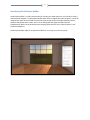
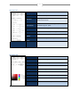
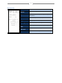
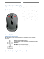
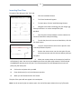
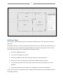
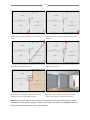
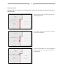
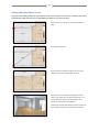
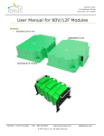
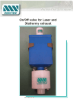
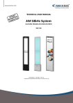
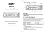
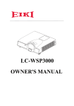
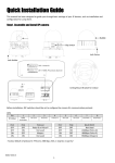
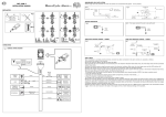
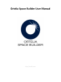
Ortelia Space Builder User Manual http://ortelia.com 1 Table of Contents Introducing Ortelia Space Builder ............................................................................................................. 2 System Requirements ........................................................................................................................3 1. Operating system: ............................................................................................................................ 3 2. Hardware: ........................................................................................................................................ 3 Minimum Graphics card specification ...................................................................................................... 3 Getting Started ..................................................................................................................................4 The Space Builder Interface ...................................................................................................................... 4 The File Menus .......................................................................................................................................... 5 The Build work panel in detail .................................................................................................................. 6 3. The Inserts Tab ................................................................................................................................. 8 Keyboard functions and Navigating ....................................................................................................9 Plan View Mode ........................................................................................................................................ 9 Preview (3D) Mode ................................................................................................................................... 9 4. Keyboard functions (Directional Keys)............................................................................................. 9 Mouse Functions (Selecting objects, looking around) .............................................................................. 9 Moving and Turning ................................................................................................................................ 10 Importing Floor Plans .............................................................................................................................. 11 Building a Space ............................................................................................................................... 12 Splitting Walls ......................................................................................................................................... 14 Adding additional Space Spaces.............................................................................................................. 15 Adding Internal Walls .............................................................................................................................. 16 Adding Doorways, Doors and Windows ................................................................................................. 18 Setting the geographical position and orientation of the Space ............................................................ 21 Adding colour to Walls ............................................................................................................................ 23 Changing floor coverings......................................................................................................................... 24 Saving your Space for use in Ortelia Set Designer .................................................................................. 24 Help and Support ............................................................................................................................. 25 2 Introducing Ortelia Space Builder Ortelia Space Builder™ is a 3D interactive tool for creating 3D space spaces for use in Ortelia Curator™ and Ortelia Set Designer™. Ortelia Space Builder allows users to import floor-plans of spaces. A scale 3D model of the space can be created from the floor-plans as well as the inserting of doorways, doors, windows and square holes in walls. Users can set ceiling and wall height and wall thickness independently. Walls can be painted and the resulting space saved for use in Ortelia Curator™ and Ortelia Set Designer™. Ortelia Space Builder requires no specialised CAD skills, it as easy to use and very quick. 3 System Requirements The following hardware and software configurations are recommended for running Ortelia Space Builder. Operating system: Microsoft Windows XP® (SP3) Microsoft Vista®. Microsoft Windows 7® Macintosh and Linux operating systems are not supported. Hardware: Recommended minimum of 2Gb of RAM Intel Core 2 Duo or Quad Core processor or above DirectX 9.0c (and above) capable graphics card with a minimum of 512Mb graphics memory (we recommend Nvidia graphics cards, see below) Important Note Ortelia Space Builder leverages many of the latest developments in graphics cards technology. Specifically, the interactive environment utilizes Microsoft DirectX Shaders (Shader Model 3 support and above). Your graphics card should support Microsoft DirectX 9c and above to ensure that your environment will display correctly. The following graphics cards are a minimum specification required to run Ortelia Space Builder. Minimum Graphics card specification ATI Radeon HD 3800 Series and above - 512Mb Memory and above NVIDIA GeForce 8 Series and above - 512Mb Memory and above Note: We do not recommend the use of integrated motherboard graphics cards. It is highly recommended that a stand-alone graphics card be used. 4 Getting Started Ortelia Space Builder is installed Ortelia Set Designer™. To start Ortelia Space Builder™ go to the Windows start menu and navigate to the Ortelia Set Designer menu. Click on the Ortelia Space Builder link with your Left Mouse Button (LMB). Note: Load time will depend on the hardware configuration you are using. Refer to our recommended hardware configuration above. The Space Builder Interface There are three key areas within the environment. These are: I. The File Menus II. The Build Panel III. The Build Work Space File menus Build Work Space The 'Build' work panel The Ortelia Space Builder Interface 5 The File Menus The 'File' menu consists of four menu items with each menu having its own drop-down. The menu items and their drop-downs are detailed below. The 'File' menu gives users access to commonly used commands. New Create a new space Open Open an existing space file Save Save the current space Save As Save the current space with a new name Exit Exit Ortelia Space Builder The 'Edit' menu allows users to undo and redo actions. Undo (Ctrl + z) Undo the last actions Redo (Ctrl + y) Redo the undo sequence The 'View' menu allows users to switch between ‘Plan View’ and ‘Preview’. Plan View (Ctrl + p) Switch to 'Plan' view when in preview mode (3D view) Preview (Ctrl + p) Switch to 'Preview' view (3D view) when in plan view mode The 'Help' menu gives access to this help manual and information about the software. About Application credits and version number Web Go to the Ortelia website Help Opens this help document as a PDF. 6 The Build work panel in detail The 'Build' work panel is divided into four individual tabs that allow access to categorised functionality. The work panel tabs are summarised below: External Shape Tools for creating the external walls of individual space spaces, setting ceiling height and apply floor coverings Walls Tools for building and painting internal walls Inserts Tools for creating doorways, windows and hole inserts in walls Tools Tools for importing floor plans, setting drawing scale and setting space real-world position The External Shape Tab Add Space Create a new space or add another to the current build Remove Remove the selected space Ceiling Height Set the ceiling height (in cm) for the currently selected space Flooring Change the floor covering for the selected space from the preset list. 7 The Tools Tab Load Plans Load space floor plans Display Plans Show or hide the plan in the Build area Grid Size Set the grid size interval. Useful when dealing with fine scale measurements. Location information Enter the time zone, latitude, longitude, and orientation of your space Plan View Switch to Plan View from Preview View (3D mode) Preview View Switch to Preview view (3D mode) from Plan View Display Wall Codes Selected Wall Code Show or hide the wall codes Create Create a internal wall Detach Detach a section of wall Split Split a wall into two equal sections Delete Delete the selected wall Height Set the wall height Width Set the wall thickness Colour The colour selection space for choosing a wall colour Save Save the current wall colour Flood Paint all the walls in the space with the saved colour Shows the code of the currently selected wall The Walls Tab 8 The Inserts Tab Add Insert Add an insert in a wall Remove Remove an insert from a wall Type Select between, Window, Door Way, Hole or fixed door (Closed door) Width Set the width of the insert (in cm) Height Set Height of the insert (in cm) Full Height Checkbox for full floor to ceiling insert Distance From Floor Repeat Horizontal Repeat Vertical Distance of the bottom of the insert from the floor Repeat the insert horizontally Repeat the insert vertically 9 Keyboard functions and Navigating There are a number of methods for interacting and moving around inside the Ortelia Space Builder™. A combination of keystrokes and mouse functions can be used to navigate. Plan View Mode There are only two mouse functions needed to use and navigate in Plan View mode. The following table summarizes these functions. MMB LMB RMB Left Mouse Button (LMB) – This button is the action button. You can use it to select/move walls, and complete input actions such as check boxes. Middle Mouse Button (MMB) - The middle mouse button is used to pan around the work space. Click and hold the MMB and move your mouse to Pan. The scroll wheel can be used for zooming in and out in Plan View. Preview (3D) Mode Keyboard functions (Directional Keys) Both the arrow keys and the W,S,A,D keys can be used as directional keys to move around the environment. Arrow keys allow the following movement: Forward (Up arrow, Backwards (Down Arrow), Left (Left arrow) and Right (Right Arrow) W,S,A,D keys allow the following movement: Forward (W key), Backwards (S Key), Left (A Key) and Right (D Key) Mouse Functions (Selecting objects, looking around) The mouse buttons serve various functions. 10 LMB RMB Left Mouse Button (LMB) – This button is the action button. You can use it to select/move walls, and complete input actions such as check boxes. Right Mouse Button (RMB) – This button is used to rotate about the 3D preview environment. Hold the RMB down and then move your mouse sideways to rotate about. Use this in combination with the direction keys to move freely around the environment. For example, you can simply use the forward and backward directional keys to move in those directions while holding down the RMB to steer. Note: This is a very effective and efficient way to navigate the 3D environment. Hint: You can travel faster through the 3D environment by holding down the 'SHIFT' key while moving. Moving and Turning Use either the arrow keys or the W,S,A,D keys to move forward, backwards or pan sideways. Click and hold down the RMB in combination with the directional keys to turn corners and look around. The figure below demonstrates moving forward in the 3D environment while using the mouse to steer. OR Hold down either the Up Arrow key or the W key + and Hold down the Right Mouse Button while moving the mouse sideways 11 Importing Floor Plans To import a floor plan go to the 'Tools' tab. 1. Click the 'Load Plans' button. 2. The 'Plans' window will appear. 3. To Load a plan, click the 'Load Plan Image' button. 4. Navigate to the folder containing your plan image (.jpg format) and select it or use the example floor plan provided. 5. Once the plan has been loaded, it can be scaled to the correct real-world size ready for building. 6. To scale the plan to the correct real-world size, click the 'Set Scale' button. 7. Use your mouse wheel to zoom into the plan for more accurate placement of points. 8. Position the mouse cursor over the start point for your scale measurement and click with the LMB to place your first point. 9. Move your mouse pointer to the next point (a red line will be drawn). Note: You can use your MMB to pan across the plans while zoomed in. Click and hold the MMB while panning across the plan. The red measurement line will disappear but you can still place your final scale point. 10. Click on the end point with your LMB 11. Enter the distance (in cm) in the Distance input box. 12. When you are finished click the 'Ok' button. The plan of the space will now appear in the workspace. Note: You do not need a plan to create a space. You can build a space without the use of a floor plan. 12 Building a Space The first step in creating a space space is to create the individual spaces. To do this go to the 'External Shape' tab. Note: Before starting, it is useful to set the grid intervals (via the ‘Tools’ Tab) that you want to work at. If for example you have a measurement length of 3950mm you should set your grid size to 5cms so that you can accurately snap to 5cm increments when creating your space. 1. Click on the 'Add Space' button. 2. Your cursor will change to a crosshair. 3. Click with the LMB on the first point where you want to start the external wall. 4. Move your cursor to the next point and click with the LMB to add the next point. 5. Trace your way around the first space space and finish the space by pressing 'Enter' on your keyboard. 6. The sequence below shows this process for creating the first space n the example file. Note. If you do not want to complete the space simply press the 'Escape' key on your keyboard to abort the drawing operation. 13 1. Place the cursor over the first point and click with the 2. Place the cursor over the next point point and click with LMB the LMB 3. Continue around Space space one 4.Continue to add points 5. Press 'Enter' to complete the space. Set your ceiling 6. View your room in 3D view by clicking the 'Preview' height (in cm) in the 'Ceiling Height' input box. button in the 'Tools' tab or using the shortcut Ctrl + p Note: When creating a space be sure to take into consideration where other walls may join the space and add points in these places. In figure 5 above 3 points need to be added in the highlighted section to account for where Gallery spaces 2 and 3 adjoin Gallery 1 14 Splitting Walls Individual walls can be split into multiple segments if needed. The following steps describe how to split and move walls. 1. Select a wall by clicking on it with the LMB. The wall will be highlighted in red. 2. In the 'Walls' Tab click the 'Split' Button. The wall will now by split in equal halves. 3. Click and hold the LMB on one end of the highlighted section of wall and move it to a new position. Release the LMB to finish. 15 Adding additional Space Spaces The process for adding additional space spaces to the current space is the same as creating a new space. The following steps describe how to add additional spaces to your current build. 1. Place the cursor over the first point and click with the LMB 2. Continue to add points 3. Press 'Enter' to complete the space. Set your ceiling height (in cm's) in the 'Ceiling Height' input box. 4. View your room in 3D view by clicking the 'Preview' button in the 'Tools' tab or using thhe shortcut Ctrl + p. In this example Space space One ceiling height is set at 320cm's an Space space Two at 280cm's. Note that the common walls between the two spaces have been removed. These will be replaced by internal walls 16 Adding Internal Walls When you have all the spaces added to your space you can begin to add internal walls. The following steps describe the process for adding internal walls to your space. To add internal walls go to the 'Walls' Tab. 1. This 3D preview shows the entire space completed without internal walls. In this example Space 1 has a celing height of 320 cm, Space 2 is 290 cm and Space 3 is 270 cm. 2. The process for adding an internal wall is the same as that for creating external shape. Place the cursor over the first point and click with the LMB 3. Continue to add points 17 4. Continue to add points 5. Add points where you want other walls to snap to. 6. Press 'Enter' to complete the wall 7. View your room in 3D view by clicking the 'Preview' button in the 'Tools' tab or using the shortcut Ctrl + p. 18 Adding Doorways, Doors and Windows Adding doorways, Doors, Windows and Holes is very simple. To add inserts go to the 'Inserts' tab. The following steps describe how to add inserts into the walls of your current build. 1. From the 'Inserts' Tab choose 'Door Way' from the 'Type' drop-down menu 2. Click on the 'Add Insert' button and move your cursor over the wall where you want the doorway to be placed. Note that as you move the insert the distance from each wall is displayed. Set the width and height of the doorway in the relevant input boxers. Note that if an insert is selected, the dimensions/type/etc from that insert will be used for the new insert. 3. Continue to add doorways as shown and setting their width and height. 4. From the 'Inserts' Tab choose 'Fixed Door' option from the 'Type' drop-down menu. Place the door as shown and set the desired width and height. 19 5. This 3D preview shows the fixed door in place. 6. Inserts can be manipulated in the 3D view as well. Simply click on a doorway with the LMB and drag it where you want it. If the door is above floor level change the 'Distance From Floor' input to 0. 7. To add a hole in a wall select 'Hole' from the 'Type' dropdown menu and click on the wall that you would like the insert in. You can do this in Plan view and Preview mode. Set the width and height of the hole. You can adjust the position of the hole interactively in Preview Mode. 8. To add a window in a wall select 'Window' from the 'Type' drop-down menu and click on the wall that you would like the insert in. You can do this in Plan view and Preview mode. Set the width and height of the window. You can adjust the position of the window interactively in Preview Mode. 20 Windows can also be tiled by inputting the number of horizontal and vertical repeats in the relevant input boxes in the 'Inserts' tab. Fixed doors can also be tiled horizontally. The following are some examples of windows set at varying repeats horizontally and vertically. Single window. One horizontal repeat and one vertical repeat Four horizontal repeats and one vertical repeat Four horizontal repeats and one vertical repeat with the 'Full Height' checkbox activated Four horizontal repeats and four vertical repeats with the 'Full Height' checkbox activated 21 Setting the geographical position and orientation of the Space To set your space in real-world space go to the 'Tools' tab. 1. 2. 3. Set you timezone relative to GMT using the 'Time' slider Set the Latitude and the Longitude using the sliders Set the orientation of the space using the slider. O° is Due North, 90° due East, 180° is Due South and 270° is Due West. To test the effects of light and shadow resulting from exterior light use the 'Time' slider. The following examples are for a space located at Latitude 27°25'S and Longitude 153° 9' E. 5 AM 9 AM 5 PM 22 View from Space number two at 5 AM 23 Adding colour to Walls All walls in the space can be painted by accessing the 'Walls' Tab. In addition it is possible to change the default floor covering for each space space by accessing the 'External Shape' Tab. Note that wall colours and floor coverings added in Space Builder are fixed and cannot be changed when imported into Ortelia Set Designer™. 1. To Paint a wall the 'Walls' tab must be active. Select the wall you want to paint with your LMB. Choose the colour you want to use from the Colour box and colour bar. 2. The wall will change to reflect the colur chosen. If you want to paint other walls the same colour click the 'Save' button in the 'Walls' tab. 3. With the colour saved you can now select more walls with the LMB and they will change to the saved colour. 4. Make your way around selecting the walls you want to paint. 24 5. Continue painting. Changing floor coverings 1. To change floor coverings the 'External Walls' tab must be active. Select the space that you want to change (in either plan view or preview mode) and then scroll through the available pre-defined floor coverings in the 'Flooring' list. Select the floor covering you would like to apply by clicking on it witht he LMB 2. Priview mode showing all three space spaces with different floor coverings. Saving your Space for use in Ortelia Set Designer Save your space by going to the 'File' menu and selecting 'Save' or 'Save As' and navigating to the folder you want to save to. There may be instances where you need to add your space to the list of saved spaces in Ortelia Set Designer for future use. The following steps will guide you through the process. 1. Locate the space file you would like to add. The extension will be .ort, for example, MySpace.ort. 2. You need to copy this space file to the 'spaces' folder in the Ortelia Curator program folder. (Typically this will be C:\Program Files (x86)\Ortelia Set Designer\spaces) 3. The next time you start Ortelia Set Designer you space will appear in the list. The next time you start Ortelia Curator you gallery will appear in the list. 25 Help and Support Support Options: Website: http://orteliacurator.com Forums: http://ortelia.com/Forums/ Email: [email protected] Please allow 24 hours for support requests to be answered. Contact Details: Ortelia Interactive Spaces PO Box 3129 Newmarket , 4051 Queensland Australia