1
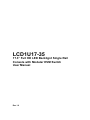
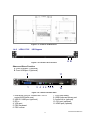
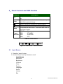
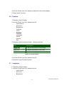
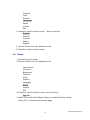
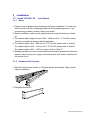
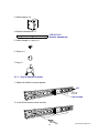
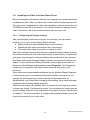
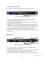
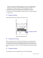
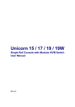
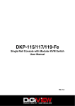
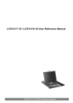
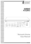
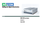
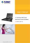
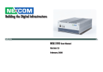
Toll Free: 1-888-865-6888 Tel: 510-226-8368 Fax: 510-226-8968 Email: [email protected] LCD1U17-35 17.3” Full HD LED Backlignt Single Rail Console with Modular KVM Switch User Manual Rev 1.0 Packing List The complete LCD1U17-35 17.3” Full HD single rail console with modular KVM switch package consist of : One 1U 19” rack mount console Two rails with front and rear bracket Two extended brackets Two Short brackets Two bracket attachments LCD1U17-35 bracket attachment One 1.8 m KVM cable (HDDB-15 / VGA + PS/2 x 2) One USB cable One DC power adapter One power cord One user manual CD One quick installation guide Two keys Six flat screws (for rail mount to console body) Six screws (for replace extended bracket) Check to make sure that the unit was not damaged in shipping. If you encounter a problem, contact your dealer. Please read this manual thoroughly, and follow the installation and operation procedures carefully to prevent any damage to the product, and / or any of the devices that connect to it. I www.RackmountMart.com Safety Instructions 1. Please read these safety instructions carefully. 2. Please keep this User’s Manual for later reference. 3. Please disconnect this equipment from AC outlet before cleaning. Don’t use liquid or sprayed detergent for cleaning. Use moisture sheet or clothe for cleaning. 4. For pluggable equipment, the socked-outlet shall be installed near the equipment and shall be easily accessible. 5. Please keep this equipment from humidity. 6. Lay this equipment on a reliable surface when install. A drop or fall could cause injury. 7. Do not leave this equipment in an environment unconditioned, storage temperature above 60 0C, it may damage the equipment. 8. The opening on the enclosure is for air convection hence the equipment from overheating. DO NOT COVER THE OPENING. 9. Make sure the voltage of the power source connect the equipment to the power outlet. 10. Please keep the power cord such a way that people can not step on it. Do not place anything over power cord. The power cord must rate for the voltage and current marked on the product’s electrical ratings label. The voltage and current rating of the cord should be greater than the voltage and the current rating marked on the product. 11. All cautions and warning on the equipment should be noted. 12. If the equipment is not in use for long time, disconnect the equipment from mains to avoid being damaged by transient over-voltage. 13. Never pour any liquid into ventilation openings; this could cause fire or electrical shock. 14. Never open the equipment. For safety reason, qualified service personnel should only open the equipment. 15. If one of the following situations arises, get the equipment checked by service personnel. The Power Cord or plug is damaged. Liquid has penetrated into the equipment. The equipment has been exposed to moisture. The equipment has not worked well or you can not get it work according to User’s Manual. II www.RackmountMart.com The equipment has dropped and damaged. If the equipment has obvious signs or breakage. III www.RackmountMart.com Index of Contents Packing List .......................................................................................................... I Safety Instructions ............................................................................................... II Index of Contents .............................................................................................. IV 1. General Information ...................................................................................... 6 1.1 Feature ................................................................................................. 6 1.2 Benefits ................................................................................................. 6 1.3 Advantage............................................................................................. 2 1.4 Product Specification ............................................................................ 3 1.4.1 LCD1U17-35 Specification ....................................................... 3 1.4.2 LCD1U17-35 I/O Diagram ........................................................ 4 2. Panel Controls and OSD Function ................................................................ 5 2.1 Input Source ......................................................................................... 5 2.2 Auto Tune ............................................................................................. 6 2.3 Brightness ............................................................................................. 6 2.4 Contrast ................................................................................................ 6 2.5 Color ..................................................................................................... 7 2.6 Position ................................................................................................. 8 2.7 Language .............................................................................................. 8 2.8 Recall .................................................................................................... 9 2.9 Volume................................................................................................ 10 2.10 Exit .................................................................................................... 10 3. Installation .................................................................................................. 11 3.1 Install LCD1U17-35 into Cabinet ...................................................... 11 3.1.1 Notes ........................................................................................ 11 3.1.2 Hardware Kits Contents ............................................................ 11 3.1.3 Step A (Install Console) ............................................................ 12 3.1.4 Step B (Replace short bracket).................................................. 14 3.1.5 Step C (Replace extended bracket): ........................................... 16 3.1.6 Unload Steps ............................................................................ 17 3.3 Install Modular KVM Switch ................................................................ 19 3.3.1 Hardware Kits Contents ............................................................ 19 3.3.2 Install Modular KVM Switch Step .............................................. 19 3.4 Installing the Video Card and Video Driver ......................................... 21 3.4.1 Configuring the Display Settings ............................................... 21 3.4.2 Connecting the Console ............................................................ 22 IV www.RackmountMart.com 3.5 Fingerprint Scanner ............................................................................ 23 3.6 Turning on the Console....................................................................... 23 3.7 Testing the Console ............................................................................ 23 4. KVM Switch ................................................................................................ 24 V www.RackmountMart.com 1. General Information LCD1U17-35 Full-HD Patented Single Rail console industrial level input solution to optimize your space utilization by controlling your systems in just 1U. With the unique modular design, you can easily integrate more than 24 models of KVM switches with different functions and expand the connections up to 8 levels of the KVM switches. 1.1 Feature Support 1920 x 1080 Full HD resolution Provide front USB port to easy data access (optional) Easy to install, single rail design. Support Sun native resolution Support 18 various keyboard languages (increasing) Bright Active TFT display OSD function for LCD display and KVM switch Durable keyboard with touchpad Sun keys (optional) Front USB HUB port (optional) Finger Print Scanner (optional) With our fully modular IP & CAT5 modules, our customers can create 21 models of KVM Switch from 7 basic models. 1.2 Benefits 1. Cost effective solution : With our unique design and all the options, you can easily suffice the demand for your customer at reasonable cost. 2. Time to serve your customer : With the modular KVM, you can easily turn single port console into 8 / 16 / 32 ports console to serve your customer well. 3. Keep low inventory : From the 1 models of consoles and 23 models of KVM switches, IP Module and CAT5 Module, you can create total 24 models in this Series. It is the best solution for inventory control. 4. Easy to maintain : Once the defective comes from the KVM switch, you can just swap the KVM switch module without asking your customer to send the whole console back to you. VI www.RackmountMart.com 5. Save freight cost : Since you have to keep only 1 models of consoles and generate new models by yourself, you can ship all the goods by sea instead of by air. In case, you run out of the KVM switch stock, it is much cheaper to ship the KVM switch modules by air. 1.3 Advantage Easy to install: With the unique separate rail design. One man can install the LCD1U17-35 console easily. In case you need to maintain the console, you can easily uninstall without effecting the server above or below. Modular KVM switches: The user can use LCD1U17-35 console as single port console or through some simple action and few screws to be 8 / 16 even 32 ports KVM consoles. Various keyboard language support: to fit the demand of each individual countries. 2 www.RackmountMart.com 1.4 1.4.1 Product Specification LCD1U17-35 Model name LCD1U17-35 Number of ports 1 Dimension 582 x 436.4 x 44.0 mm / 20.8 x 17.2 x 1.7 inches Net Weight 13 Kg / 28.7 lbs Display Size 17.3 inches Full HD Panel Type TFT LCD Resolution Capabilities Maximum Resolution up to 1920 x 1080 (Full HD) Pixel Pitch Supports 0.198 mm x 0.198 mm Viewing Angle (CR>10) Right-Left view 140°(Typ) Up-Down View 120°(Typ) Contrast Ratio 650 : 1 Brightness White 300 cd/ m² Back Light DualLamps for Back Light Supported Colors 16.7M Colors (8-bit with FRC) Response Time Rising Time 2 ms, Decay Time 6 ms Operating System Dos, Unix, Linux, OSX, Windows ( XP, 7, 8, Server 2012 R2) Multi Platform Support PS/2 and USB System Cables VGA + PS/2 x 2 or VGA + USB x 1 cable Keyboard Mouse 106 key PS/2 keyboard with touch pad Sync 45 ~ 80 KHz Power Source 100 ~ 240 VAC input Power Consumption 10.2W for Panel Temperature Operate 0 ~ 50°C / 32 ~ 122°F Storage -20 ~ 60°C / -4 ~ 140°F Humidity 10% ~ 90% RH Chassis Construction Heavy duty steel materials Keyboard Language US, UK, German, French, Spanish, Italian, Dutch, Portuguese, Swiss, Belgium, Swedish, Norwegian, Danish, Russian, Hebrew, Arabic, Japanese, Mandarin 3 www.RackmountMart.com Figure 1-2. LCD1U17-35 Dimension 1.4.2 LCD1U17-35 I/O Diagram A B Figure 1-3. LCD1U17-35 Front View Share and Store Function A. Front USB port 1 (optional) B. Front USB port 2 (optional) 11 2 1 3 4 56 78 9 10 Figure 1-4. LCD1U17-35 Rear View 1. KVM dock (Only for Combo-free / CAT5 series KVM Switch use.) 2. USB 2.0 HUB port (optional) 3. DC in 4. VGA port 5. PS/2 keyboard 6. PS/2 mouse 4 7. PS/2-USB select 8. USB Keyboard Mouse port 9. Audio line in (optional) 10. DVI port (optional) 11.HDMI port (optional) www.RackmountMart.com 2. Panel Controls and OSD Function Controls Description Soft power on/off button. Adjacent LCD is lit when on. Auto Auto-synchronize and scale down display to any valid factory preset timings. Press to scroll the function you want to adjust. Press to scroll the function you want to adjust. Menu To access the main menu. This button also acts as the “Enter” button. GERRN RED Power Indicator RED RED ON STANDBY SUSPEND OFF Table 2-1. Panel Controls Figure 2-1. LCD1U17-35 OSD Control Bar 2.1 Input Source 1. Press the “menu” button. 2. Use the “Down” and “Up” button to scroll. Input Source Auto tune. Brightness Contrast Color Position Language Recall Volume Exit 5 www.RackmountMart.com 3. Press the“menu”button to enter,and you will see: VGA DVI HDMI AUTOSERCH 4. Use the “Down” and “Up” button to select the input source of signal. 5. Press the “menu” button to enter 2.2 Auto Tune Press the “auto tune” button. The panel will adjust the display size automatically and also tune the panel to its best condition. 2.3 Brightness 1. Press the “menu” button. 2. Use the “Down” and “Up” button to scroll. Input Source Auto tune. Brightness Contrast Color Position Language Recall Volume Exit 3. Press the“menu”button to enter. 4. Use the“Down”and“Up”button to adjust the brightness of the display. 5. Press the “menu” button to enter. 2.4 Contrast 1. Press the “menu” button. 2. Use the “Down” and “Up” button to scroll. Input Source 6 www.RackmountMart.com Auto tune. Brightness Contrast Color Position Language Recall Volume Exit 1. Press the “menu” button to enter. 2. Use the “Down” and “Up” button to adjust the contrast of the display. 3. Press the “menu” button to enter. 2.5 Color 1. Press the “menu” button. 2. Use the “Down” and “Up” button to scroll. Input Source Auto tune. Brightness Contrast Color Position Language Recall Volume Exit 3. Press the “menu” button to enter. And you will see: Icon Description 9300°K To set CIE coordinates at 9300°K color 7500°K To set CIE coordinates at 7500°K color 6500°K To set CIE coordinates at 6500°K color User To set user defined CIE Auto color To auto adjust color Return To exit and return to the previous page Table 2-2. Icon Description 7 www.RackmountMart.com 4. Use the “Down” and “Up” button to adjust the color of the display. 5. Press “menu” to enter. 2.6 Position 1. Press the “menu” button. 2. Use the “Down” and “Up” button to scroll. Input Source Auto tune. Brightness Contrast Color Position Language Recall Volume Exit 3. Press the “menu” button to enter. And you will see: Icon Description Image Pos To adjust the position of the image. OSD Pos To adjust the position of the OSD. Return To exit and return to the previous page Table 2-3. Icon Description 4. Use the “Down” and “Up” button to scroll. 5. Press the “menu” button to enter. 2.7 Language 1. Press the “menu” button. 2. Use the “Down” and “Up” button to scroll. Input Source Auto tune. Brightness 8 www.RackmountMart.com Contrast Color Position Language Recall Volume Exit 3. Press the “menu” button to enter. And you will see: English Deutsch Francais Italiano Espanol 4. Use the “Down” and “Up” button to scroll. 5. Press the “menu” button to enter. 2.8 Recall 1. Press the “menu” button. 2. Use the “Down” and “Up” button to scroll. Input Source Auto tune. Brightness Contrast Color Position Language Recall Volume Exit 3. Press the “menu” button to enter, and you will see: Yes/ No 4. Select “Yes” button then ‘Menu” button to recall the factory setting. Select “No “ to return to the previous page. 9 www.RackmountMart.com 2.9 Volume For Audio version use. 2.10 Exit Press the “exit” button to quit OSD menu. 10 www.RackmountMart.com 3. 3.1 3.1.1 Installation Install LCD1U17-35 into Cabinet Notes 1. Please check all peripherals according the list before installation. To make sure that the whole unit was not damaged and lost during shipping process. If you encounter any problem, please contact your dealer. 2. Before installation, make sure all peripherals and computer have been turned off. 3. The cabinet depth range must be in 504 ~ 1000 mm for 17.3” Full-HD console. Contact your dealer for deeper cabinet application. 4. The cabinet depth is 614 ~ 800 mm for 17.3” Full-HD, please refer to “Step A”. The cabinet depth is 504 ~ 614 mm for 17.3” Full-HD, please refer to “Step B”. The cabinet depth is 800 ~ 1000 mm, please refer to “Step C”. 5. Reliable grounding of rack-mounted equipment should be maintained. Particular attention should be given to supply connections other than direct connections to the branch circuit. 3.1.2 Hardware Kits Contents 1. Rail with front and rear bracket x 2 (Please identify the brackets. Right and left sides are different.) 2. Extended bracket x 2 11 www.RackmountMart.com 3. Short bracket x 2 4. Bracket attachment x 2 LCD1U17-35 bracket attachment 5. Screw (length = 6 mm) x 6 6. Screw x 6 7. Key x 2 3.1.3 Step A (Install Console) 1. Adjust rail until two screws appear. rail two screws 2. Loose (Not remove) seven screws. 12 www.RackmountMart.com 3. Adjust rail to fit your cabinet 4. Install front and rear bracket on cabinet. 5. Tight seven screws up. 6. Repeat step 1~5 for the other side. 7. Push console into rails. (Be careful rear box loose when take out console from carton.) 13 www.RackmountMart.com 8. Unlock and pull rail–lock switch (left and right at the same time) then push console to the end. lock unlock rail-lock switch 9. Install three screws (length = 6 mm) in rear of the console. (Both sides) 10. Finish installation as below. 3.1.4 Step B (Replace short bracket) 1. Remove seven screws. 14 www.RackmountMart.com 2. Take two original brackets out. original bracket original bracket 3. Put short bracket to rear of the rail. short bracket 4. Install four screws (don’t tight-up) to combine rail, short bracket and bracket attachment. bracket attachment short bracket 5. Repeat step 1 ~ 4 for the other side. 6. Repeat step 3 ~ 10 of step A to finish the installation. 15 www.RackmountMart.com 3.1.5 Step C (Replace extended bracket): 1. Loose (Not remove) seven screws. 2. Release six screws. 3. Take rear bracket out. original bracket 4. Adjust rail and input extended bracket to rear of the rail then adjust extended bracket to fit your cabinet. Install unless 2~3 screws (don’t tight-up) upon the length you need. One is forbidden. extended bracket 5. Repeat step 1 ~ 4 for the other side. 6. Repeat step 3 ~ 10 of step A to finish the installation. 16 www.RackmountMart.com 3.1.6 Unload Steps 1. Make sure the console has locked and turned off. 2. Loose two thumb screws and pull modular KVM switch out. 3. Release three screws in rear of the console. (Both sides) 4. Unlock. 5. Pull console out until console lock. 17 www.RackmountMart.com 6. Pull rail-release switch and pull console out.(Both sides. Be careful when pull out console.) rail-release switch 7. Push rail-lock switch on the rail and push rail back. (Both sides) rail-lock switch on the rail 18 www.RackmountMart.com 3.3 Install Modular KVM Switch 3.3.1 Hardware Kits Contents 1. Bracket with thumb screw x 2 2. Screw (length = 6 mm) x 4 3.3.2 Install Modular KVM Switch Step 1. Install two screws (length = 6 mm) to combine bracket and KVM switch. (Both sides) 19 www.RackmountMart.com 2. Push KVM switch into the rails from rear of cabinet. plastic rail of KVM switch rear view of rail 3. Tight thumb screw of bracket up to fix KVM switch in console and finish installation. (Both sides) 20 www.RackmountMart.com 3.4 Installing the Video Card and Video Driver Before connecting the LCD console, make sure your computer has a video card already installed for the panel. After you connect the console, install the video software driver. The video driver is supplied by the video card manufacturer and may be found on the CD-ROM that came with your computer. If you need information on installing a video card or video driver, refer to the manual that came with your video card. 3.4.1 Configuring the Display Settings After connecting the console and turning on your computer, you may need to configure one or more of the following display settings: Display mode (also called desktop area or video resolution) Refresh rate (also called vertical scan rate or vertical sync) Color depth (also called color palette or number of colors) Each video card has several controls that let you adjust the display settings. However, the software and driver for each video card is unique. In most cases, you adjust these settings by using a program or utility provided by the manufacturer of the video card. Most video cards use the Windows Display Properties control panel to configure the display. To open the Windows Display Properties, click the right mouse button in a blank area of the Windows desktop and then select Properties. The Settings tab usually lets you change the Color Palette and the Desktop Area (x by y pixel resolution). Some video cards integrate additional features into the Windows Display Properties control panel to give you an exceptional setup that is flexible and easy to use. For example, the control panel may include an Advanced Properties button, an Adjustment tab, or a Refresh tab for changing other settings. Other video cards have a separate utility for setting display properties. Whenever you change the resolution, color, or refresh rate, the image size, position, or shape may change. This behavior is normal. You can readjust the image using the panel on-screen controls. For more information on the panel on-screen controls, refer to Chapter 2. For more information on configuring the display settings, refer to the manual that came with your video card. 21 www.RackmountMart.com 3.4.2 Connecting the Console To connect an LCD console to a computer, perform the following steps PS/2-USB switch Figure 3-1. The Rear View of LCD Console 1. Turn off your computer. You should always turn off your computer before connecting or disconnecting a device. 2. Connect the video (VGA) connector of the KVM cable to the video card connector on the rear panel of your computer. 3. Identify and connect the PS/2 mouse and PS/2 keyboard connector to the correct PS/2 ports on the rear panel of your computer. Or you can use USB interface to connect your computer. ( Use PS/2-USB switch to select your interface. The switch has to be on PS/2 side when you use PS/2 interface connector.) 4. Connect the AC to DC power adapter to the power inlet on the console and then to a power outlet. With USB Hub: HDMI port USB Hub port DVI port PS/2-USB switch Figure 3-2. The rear view of console (USB Hub) 1. Turn off your computer. You should always turn off your computer before connecting or disconnecting a device. 2. Connect the video (VGA / DVI / HDMI) connector of the KVM cable (DVI / HDMI) to the video card connector on the rear panel of your computer. 3. Identify and connect the PS/2 mouse and PS/2 keyboard connector to the correct 22 www.RackmountMart.com PS/2 ports on the rear panel of your computer. Or you can use USB interface to connect your computer. ( Use PS/2-USB switch to select your interface. The switch has to be on PS/2 side when you use PS/2 interface connector.) 4. Use USB A-A cable connect USB HUB port and USB port of system. 5. Connect the AC to DC power adapter to the power inlet on the console and then to a power outlet. 3.5 Fingerprint Scanner Please install the driver from website or folder “Driver” in CD. Fingerprint Scanner Figure 3-3. Fingerprint Scanner 3.6 Turning on the Console Make sure all cables and the AC to DC power adapter are connected properly. Be sure to tighten all connector screws. Grab the front handle. Pull the console all the way out then lift the panel up. This will disengage the momentary on/off switch and the unit should power on. The LCD on the left or underneath of the panel will be green light. 3.7 Testing the Console To test that the console is working properly, perform the following steps: 23 www.RackmountMart.com 1. Power up the console, and then turn on your computer. 2. Make sure the video image is centered within the screen area. Use the OSD controls to adjust the image (see note below) or press the Auto button on the left or underneath of the panel. If the unit does not power on when the panel is pulled up, try to push the power on/off button underneath or on the left of the LCD panel to power up the unit. You can adjust the horizontal and vertical position, contrast, and brightness to better suit your video card and your personal preference. Refer to Chapter 2 for more information on using the on-screen menu to adjust the video display. Before you begin, make sure that powers to all the devices you will be connecting up have been turned off. To prevent damage to your installation due to ground potential difference, make sure that all the devices on the installation are properly grounded. Consult your direct vendor for any technical issues if necessary. 4. KVM Switch For the KVM switch user manual, please go back to the main menu and select “KVM Switch“. 24 www.RackmountMart.com