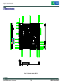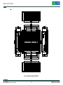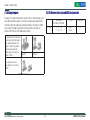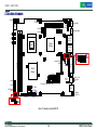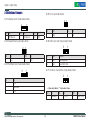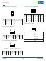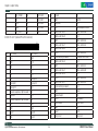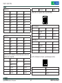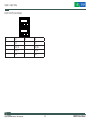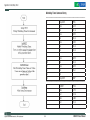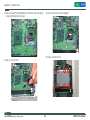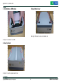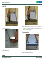
1
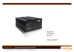
Building the Digital Infrastructure NISE 3110 User Manual Version 1.3 March, 2008 Preface Copyright Notice FCC Class A Copyright © 2006 NEXCOM All rights reserved. No part of this manual may be reproduced, transmitted, transcribed, stored in a retrieval system, or translated into any language or computer language, in any form or by any means (electronic, mechanical, photocopying, recording, or otherwise), without the express written permission of NEXCOM Information provided in this manual is intended to be accurate and reliable. However, the original manufacturer assumes no responsibility for its use, nor for any infringements upon the rights of third parties that may result from such use. This equipment has been tested and found to comply with the limits for a Class A digital device, pursuant to part 15 of the FCC Rules. These limits are designed to provide reasonable protection against harmful interference when the equipment is operated in a commercial environment. This equipment generates, uses, and can radiate radio frequency energy and, if not installed and used in accordance with the instruction manual, may cause harmful interference to radio communications. Operation of this equipment in a residential area is likely to cause harmful interference in which case the user will be required to correct the interference at his own expense. Acknowledgements Installation Suggestions Intel and Pentium are trademarks of Intel Corporation. Microsoft Windows® is a registered trademark of Microsoft Corp. All other product names or trademarks are properties of their respective owners. Ensure you have a stable, clean working environment. Dust and dirt can get into components and cause a malfunction. Use containers to keep small components separated. Adequate lighting and proper tools can prevent you from accidentally damaging the internal components. Most of the procedures thatfollow require only a few simple tools, including the following: A Philips screwdriver A flat-tipped screwdriver A grounding strap An anti-static pad Using your fingers can disconnect most of the connections. It is recommended that you do not use needlenose pliers to disconnect connections as these can damage the soft metal or plastic parts of the connectors. Declaration of Conformity CE This product has passed the CE test for environmental specifications when shielded cables are used for external wiring. We recommend the use of shielded cables. Please contact your local supplier for ordering information. This product has passed the CE test for environmental specifications. Test conditions for passing included the equipment being operated within an industrial enclosure. In order to protect the product from being damaged by ESD (Electrostatic Discharge) and EMI leakage, we strongly recommend the use of CE-compliant industrial enclosure products. Copyright © 2006 NEXCOM International Co., LTD. All rights reserved NISE3110 User Manual Preface Handling Precautions Always disconnect the unit from the power outlet whenever you are installing or fixing a component inside the chassis. If possible, always wear a grounded wrist strap when you are installing or fixing a component inside the chassis. Alternatively, discharge any static electricity by touching the bare metal chassis of the unit case, or the bare metal body of any other grounded appliance. Hold electronic circuit boards by the edges only. Do not touch the components on the board unless it is necessary to do so. Do not flex or stress the circuit board. Use the correct screws and do not overly tighten them. Keep the original packaging and static-protective bag in case the unit has to be returned. Copyright © 2006 NEXCOM International Co., LTD. All rights reserved NISE3110 User Manual Warranty and RMA NEXCOM RMA Policy 2.5 Any products returned by NEXCOM to other locations besides the customers’ site will bear an extra charge and will be billed to the customer. 1.Warranty Period 3. Repair service charges for out of warranty products NEXCOM manufactures products that are new or equivalent to new in accordance with industry standard. NEXCOM warrants that products will be free from defect in material and workmanship for 24 months beginning on the date of invoice by NEXCOM. HCP series products (Blade Server) which are manufactured by NEXCOM are covered by a three year warranty period. NEXCOM will charge for out of warranty products in two categories, one is basic diagnostic fee and another is component (product) fee. System level Component fee: NEXCOM will only charge for main components, such as SMD chip, BGA chip, etc. Passive components will be repaired for free, ex: resistor, capacitor. 2. RMA (Return Merchandise Authorization) Customers shall enclose the “NEXCOM RMA Service Form” with the returned packages. Items will be replaced with NEXCOM products if the original one is not able to be repaired. Ex: motherboard, power supply, etc. Customers must collect all the information about the problems encountered and note anything abnormal or, print out any on-screen messages, and describe the problems on the “NEXCOM RMA Service Form” for the RMA number apply process. Replaced with 3rd party products if needed. If RMA goods can not be repaired, NEXCOM will return it to customer without any charge. Customers can send back the faulty products with or, without accessories (manuals,cable, etc.) and any unnecessary components from the card, such as CPU and RAM. If the components were suspected as part of the problems, please note clearly that which components are included. Otherwise, NEXCOM is not responsible for the devices/parts. Board level Component fee: NEXCOM will only charge for main components, such as SMD chip, BGA chip, etc. Passive components will be repaired for free, ex: resistors, capacitors. If RMA goods can not be repaired, NEXCOM will return it to customer without any charge. Customers are responsible to for the safe packaging of defective products are durable enough to be resistant against further damage and deterioration during transportation. In case of damages occurred during the transportation, the repair is treated as “Out of Warranty.” Copyright © 2006 NEXCOM International Co., LTD. All rights reserved NISE3110 User Manual Warranty and RMA Global Service Contact Information NEXCOM Japan 10F, Nakagin-Shiroyama Building, 8-16-13 Ginza Chuou-Ku, Tokyo, Japan 104-0061 Tel: 81-3-3524-4250 Fax: 81-3-3524-4252 Email: [email protected] Website: www.nexcom-jp.com Headquarters NEXCOM International Co. Ltd. 18F, No.716, Chung-Cheng Road Chung-Ho City, Taipei County 235, Taiwan, R.O.C. Tel: 886-2-8228-0606 Fax: 886-2-8228-0501 Email: [email protected] Website: www.nexcom com.tw China NEXCOM China Room 301, Block E, Power Creative Building, No.1 Shangdi East Rd. Haidian District Beijing, 10085, China Tel: 86-10-5885-6655 Fax: 86-10-5885-1006 Email: [email protected] Website: www.nexcom.cn USA NEXCOM USA 3758, Spinnaker Court, Fremont, CA 94538, US A. Tel: 1-510-656-2248 Fax: 1-510-656-2158 Email: sales@nexcom com Website: www.nexcom.com Europe NEXCOM UK 10 Vincent Avenue, Crownhill Milton Keynew, Buckinghamshire MK8 0AB, United Kingdom Tel: 44-(0)-1908-21 88 77 Fax: 44-(0)-1908-21 88 67 Email: [email protected] Website: www.nexcomuk.co.uk Japan Copyright © 2006 NEXCOM International Co., LTD. All rights reserved NISE3110 User Manual Warranty and RMA RoHS Compliance How do you recognize NEXCOM RoHS Products? For existing products where there are non-RoHS and RoHS versions, the suffix “(LF)” will be added to the compliant product name. For example, PEAK 7220VL2G RoHS version will become PEAK 7220VL2G(LF). All new product models launched after January 2006 will be RoHS compliant. They will use the usual NEXCOM naming convention. For example, PEAK 870VL2, NBP14570, EBC 420 etc. All RoHS compliant model and component manufacturing part numbers will be suffixed “X00” NEXCOM RoHS Environmental Policy and Status Update. Nexcom is a global citizen for building the digital infrastructure. We are committed to providing green products and services, which are compliant with European Union RoHS (Restriction on Use of Hazardous Substance in Electronic Equipment) directive 2002/95/EU, to be your trusted green partner and to protect our environment. RoHS restricts the use of Lead (Pb) < 0.1% or 1,000ppm, Mercury (Hg) < 0.1% or 1,000ppm, Cadmium (Cd) < 0.01% or 100ppm, Hexavalent Chromium (Cr6+) < 0.1% or 1,000ppm, Polybrominated biphenyls (PBB) < 0.1% or 1,000ppm, and Polybrominated diphenyl Ethers (PBDE) < 0.1% or 1,000ppm. In order to meet the RoHS compliant directives, NEXCOM has established an engineering and manufacturing task force in to implement the introduction of green products. The task force will ensure that we follow the standard NEXCOM development procedure and that all the new RoHS components and new manufacturing processes maintain the highest industry quality levels for which NEXCOM are renowned. The model selection criteria will be based on market demand. Vendors and suppliers will ensure that all designed components will be RoHS compliant. Copyright © 2006 NEXCOM International Co., LTD. All rights reserved Manual Revision History Revision Date Description 1.0 Sep., 07 First Edition, V1.0 1.1 Nov. 07 Add Appendix C “power consumption” 1.2 Feb.,08 Correct P28 GPIO pin definition (J11) 1.3 March, 08 Add the Appendix E: Display Setting Modify the Appendix B: GPIO Programming guide (add the note for SPC150) NISE3110 User Manual Warranty and RMA Copyright © 2006 NEXCOM International Co., LTD. All rights reserved NISE3110 User Manual Table of Content Table of Content 1.6 Board Layout........................................................................................... 14 Copyright Notice............................................................................................. 2 Figure 1.2 Top View ofr the EBC 576............................................................. 14 Acknowledgements.......................................................................................... 2 1.7 Dimension Drawing ................................................................................ 15 Declaration of Conformity................................................................................ 2 Figure 1.3: Dimension drawing of EBC 576 . ................................................ 15 Installation Suggestions.................................................................................. 2 Figure 1.4 Dimension drawing of NISE 3110 . .............................................. 16 Handling Precautions...................................................................................... 3 Chapter 2 Jumper Setting............................................... 17 NEXCOM RMA Policy..................................................................................... 4 2.1 Setting Jumpers ..................................................................................... 18 Global Service Contact Information................................................................. 5 Table 2.1 Setting Jumpers............................................................................. 18 RoHS Compliance........................................................................................... 6 2.2 PCI Device interrupt and BUS Assignments............................................ 18 Manual Revision History................................................................................. 6 2.3 Location of Jumpers ............................................................................... 19 Table of Content............................................................................................... 8 Figure 2-1: Jumper Location of EBC 576...................................................... 19 Chapter 1 General Information......................................... 10 2.4 Definition of Jumpers ............................................................................. 20 1.1 Product Overview.................................................................................... 11 1.2 Block Diagram......................................................................................... 11 Figure 1.1 : Block Diagram of EBC 576......................................................... 11 1.3 Specifications.......................................................................................... 12 1.4 Ordering Information............................................................................... 13 1.5 Packing Materials Checklist.................................................................... 13 Copyright © 2006 NEXCOM International Co., LTD. All rights reserved NISE3110 User Manual Table of Content Appendix A-Watchdog Timer............................................ 33 Watchdog Timer Common library . ............................................................... 34 Appendix B-GPIO Programming Guide................................. 36 Appendix C-Power Consumption....................................... 38 Appendix D-Installation Guide.......................................... 40 D.1 Handling Precautions.............................................................................. 41 D.2 Packing List............................................................................................ 41 D.3 Installation.............................................................................................. 42 1.Open Top Cover.......................................................................................... 42 2.Install/Remove CPU................................................................................... 42 3. Install/Remove RAM module..................................................................... 44 4.Close Top Cover......................................................................................... 44 5.Open Bottom Cover.................................................................................... 44 6.Install HDD ................................................................................................ 45 7.Close Bottom Cover................................................................................... 45 Appendix E-Display Seting.............................................. 46 Copyright © 2006 NEXCOM International Co., LTD. All rights reserved NISE3110 User Manual Chapter 1 General Information Fan-less BOX Computer NISE 3110 Chapter 1 General Information 1.1 Product Overview 1.2 Block Diagram Featuring Intel 945GME & ICH7 chipsets, the NISE 3110 fan-less box computer supports Intel’s Core 2 Duo /Celeron M processor with 533/667 MHz FSB and DDR2 667/533 memory. The rugged NISE 3110 fan-less box computer is designed for space-critical application requires extreme reliability, low-power consumption and versatile I/O configuration. For added flexibility, the NISE 3110 also boasts three RS232 ports, one RS232/422/485 port and one PCI expansion slot. Intel® Core 2 Duo, Core Duo,Celeron M 533 / 667 MHz FSB LVDS DDR2 Channel A Intel® 945GME VGA DVI Chrontel 7307 For data storage, the NISE 3110 provides one CompactFlash socket and one 2.5" HDD drive bay. The System supports ATX mode power feature and can accept a wide range of power supplies from 12 V DC to 30 V DC. Front Panel Internal Conn. 0/1 2,3/4/5 CF & IDE Housed in a compact 195 mm x 268 mm x 80 mm heavy-duty aluminum chassis, the NISE 3110 is designed for reliable, maintenance-free industrial computing. The NISE 3110 fan-less box computer offers a cost-effective solution for a multitude of mission-critical embedded computing applications in automation, machine control, and POS systems. 4 Lanes DDR2 Slot DDR2 Slot 1 x PCIe Interface 2GB/s USB2.0 Intel® ICH7-M DH UltraDMA 33/66/100 SATA 1 SATA 2 DDR2 DIMM Modules DDR2 533 / 667 MHz DDR2 Channel B PCIex1 Port (1) RJ45 (LAN1) Marvell 88E8053 GbE RJ45 (LAN2) PCI-Slot PCI 32 Bit / 33 MHz Bus SATA Marvell 88E8053 GbE ALC655 LPC BUS SIO1 SIO2 IT8712F KB/MS Support Intel® Core 2 Duo / Core Duo/ Celeron® M processors IrDA COM1,2 LPT IT8712F GPIO COM3,4 Intel® 945GME Chipsets Figure 1.1 : Block Diagram of EBC 576 Dual 1000/100/10Mbps LAN ports 6 x USB2.0/ VGA / DVI/ 4 x SIO One PCI Expansion Slot Copyright © 2006 NEXCOM International Co., LTD. All rights reserved 11 NISE3110 User Manual Chapter 1 General Information 1.3 Specifications I/O Interface-Front Main Board EBC 576 Support Intel® Core 2 Duo, Core Duo, Celeron® M family processors with 533/667 MHz Customized logo(Optional) HDD Access/Power/LAN status LEDs 2 x USB 2.0 ports ATX power on/off switch I/O Interface-Rear Intel® Embedded Processor Reference List (Intel® Longevity CPU): Core Duo Processor (T2300E) 1.66 G Core Duo Processor (T2500) 2.0G Celeron® M 530 1.73G Celeron® M 440 1.86G 2 x PS/2 connectors (KB/MS) 1 x VGA connector 4 x USB 2.0 ports 2 x GbE LAN Ports Chipset Intel® 945GME Graphics Memory Controller Hub (GMCH) 4 x Serial Ports, with 1x DB44 connector ( Three ports support RS232, One port supports RS232/422/485) Intel® 82801 GBM ICH7 Mobile digital Home (ICH7-M) 1 x DVI interface Main Memory 1 x Mic-in and 1 x Speaker-out 2 x 240 pin DDR2 533/667 DIMM sockets, up to 2 GB unbuffered non-ECC DDR SDRAM (Max. 3G Capacity supported) 1 x 2-pin connector output for remote power on/off switch DC-in power connector for +12V ~+30V DC power input Expansion Slot Device Supports one 32-bit/ 33MHz PCI card 1 x On-board CompactFlash socket PCI Length support: 160 mm (When 2.5" HDD installed) 240 mm (When no HDD is installed) Copyright © 2006 NEXCOM International Co., LTD. All rights reserved 1 x Internal 2.5" HDD drive bay 12 NISE3110 User Manual Chapter 1 General Information 1.4 Ordering Information Power Input DC to DC power designed for on-board support of 12 to 30 VDC (Max: 120 Watts) Barebone NISE 3110 (P/N: 10J0031100X0) RoHS Compliant Intel® Core 2 Duo, Core Duo, Celeron® M Fanless Bare-Bone System, with one PCI expansion slot 1 x External 120 W AC adapter Power input: 100 to 240 V AC 2 A 50/60 Hz Power output: 19 VDC 1.5 Packing Materials Checklist Dimensions 195 mm (W) x 268 mm (D) x 80 mm (H) (7.6" x 10.5" x 3.1") Construction Aluminum chassis with fan-less design Environment Operating temperature: Ambient with air flow : 0°C to 40°C (CPU loading: 70% less continently) NISE 3110 Tcase ( Surface Temperature of Chassis) 5°C to 50°C (W/HDD) -10°C to 55°C (W/CF card only) Description Q'ty Power Adapter 120W 1 Power Connector 2P 1 COM cable (1 x 44 pin connector to 4 x DB9 ports) 1 IDE Cable 1 EBC 576 CD Driver 1 EBC 576 Quick Reference Guide 1 Sliicone Heatsink Compound 1 Storage temperature: -20°C to 80°C Relative humidity: 10% to 90% (Non-condensing) Certifications CE approval FCC Copyright © 2006 NEXCOM International Co., LTD. All rights reserved 13 NISE3110 User Manual Chapter 1 General Information 1.6 Board Layout Figure 1.2 Top View of the EBC 576 Copyright © 2006 NEXCOM International Co., LTD. All rights reserved 14 NISE3110 User Manual Chapter 1 General Information 1.7 Dimension Drawing Figure 1.3: Dimension drawing of EBC 576 Copyright © 2006 NEXCOM International Co., LTD. All rights reserved 15 NISE3110 User Manual Chapter 1 General Information Figure 1.4 Dimension drawing of NISE 3110 Copyright © 2006 NEXCOM International Co., LTD. All rights reserved 16 NISE3110 User Manual Chapter 2 Jumper Setting Fan-less BOX Computer NISE 3110 Chapter 2 Jumper Setting 2.1 Setting Jumpers 2.2 PCI Device interrupt and BUS Assignments A jumper is the simplest kind of electric switch. It consists of two metal pins and a cap. When setting the jumpers, ensure that the jumper caps are placed on the correct pins. When the jumper cap is placed on both pins, the jumper is SHORT. If you remove the jumper cap, or place the jumper cap on just one pin, the jumper is OPEN. Please see the following illustrations The illustrations on the right show a 2-pin jumper. When the jumper cap is placed on both pins, the jumper is SHORT. If you remove the jumper cap, or place the jumper cap on just one pin, the Open (Off) jumper is OPEN. PCI Slot1 Configuration BUS/DEVIC/FUNCTION PCI INT# REQ# /GNT# 1 / 17 / 0 1 / 18 / 0 A,B,C,D D,A,B,C 0,1 Short (On) These illustrations show a 3-pin Jumper. Pins 1 and 2 are SHORT. Table 2.1 Setting Jumpers Copyright © 2006 NEXCOM International Co., LTD. All rights reserved 18 NISE3110 User Manual Chapter 2 Jumper Setting 2xUSB (USB1) PCI (CN5) SATA(J6) 1 1 SATA(J7) LED1 7 -12V input (J10) PCI-E Slot (CN8) 7 1 6 1 FAN(CN4) PS2 for Mouse(KM1) VGA (CN10) B2 B1 A1 A2 CPU South Bridge Compact Flash (CN9) DIMM2 DIMM1 FAN(J1) 1 1 2 1 1 JP2 1 1 1 1 ATX Switch (SW1) DVI(CN1) 1 1 1 SW2 JP6 JP7 JP5 1 1 1 1 1 1 1 JP9 JP10 JP8 GPIO(J11) 4 x COM (J12) IDE (CN6) 1 DC Power Output Conn. (J8) FAN(J2) 1 PS2 for Keyboard(KM2) 1 x LAN TOP) 2 x USB (Bot) (CON2) 1 1 1 1 1 North Bridge 21 1 x LAN TOP) 2 x USB (Bot) (CON1) LED2 LED3 8 1 USB(J3) 1 2.3 Location of Jumpers 1 2 1 14 PIO(CN7) Line Out (Top) MIC In (Bot) (U42) CD-IN (JP11) 1 DC-IN (CN11) 2 LVDS (CN2) 1 2 LVDS (CN3) 1 1 JP4 1 CCFL(J4) ATX Remote Switch (JP12) JP3 Figure 2-1: Jumper Location of EBC 576 Copyright © 2006 NEXCOM International Co., LTD. All rights reserved 19 NISE3110 User Manual Chapter 2 Jumper Setting 2.4 Definition of Jumpers JP5: I2C (1x2 pin header,2.54mm) JP2: ATX power Switch (1x4 pin header,2.54mm) 4 2 1 1 PIN Def. PIN Def. PIN Def. 1 ATX Power on 2 ATX Power on 3-4 GND Pin Def. Pin Def. 2 Data 1 CLK JP6: CMOS Status Select (1x3 pin header,2.54mm) JP3: Hardware Reset (1x2 pin header,2.54mm) 3 2 1 1 PIN Def. PIN Def. Pin Status Function 1 Reset 2 GND 1-2 Short* Normal Operation 2-3 Short Clear CMOS DATA JP4:Panel Power Select (1x3 pin header,2.54mm) 3 PIN Def. 1 VCC5 2 Panel Power 3 VCC3 Copyright © 2006 NEXCOM International Co., LTD. All rights reserved JP7: CF Master / Slave Selection (1x3 pin header,2.54mm) 1 3 1 <1-2 pin short= Master / **2-3 pin short= Slave> 20 PIN Def. PIN Def. PIN Def. 3 Slave (GND) 2 CF_CSEL 1 Master (VCC5) NISE3110 User Manual Chapter 2 Jumper Setting SW2: COM2 RS232/422/485 Select (2x10 DIP SWITCH) O N JP8: GPI/O Programming LED (2x2 pin header,2.0mm) 1 2 3 4 5 6 7 8 9 0 3 1 Mode 4 2 Pin Def. Pin Def. 3 GP21 1 GP20 4 GND 2 GND 2 3 4 5 6 7 8 9 10 RS232* OFF OFF OFF ON OFF ON OFF OFF OFF OFF RS422 OFF OFF ON OFF ON OFF ON ON ON ON RS485 ON ON OFF ON ON OFF OFF OFF OFF ON JP11: CD-IN (1x4 pin header, 2.54mm) JP9: IR Interface (1x5 pin header,2.54mm) 4 1 5 PIN Def. PIN Def. PIN Def. PIN Def. PIN Def. 5 4 GND 3 IRRX 2 CIRRX 1 VCC5 IRTX 1 JP10: RI# Signal Power Select (1x5 pin header,2.54mm) 1 Pin. Def. 1 CD-IN-L 2 AUDIO GND PWR 3 AUDIO GND PWR 4 CD-IN-R 1 5 <1-2 short: RI Power = 5v / 3-4 short: RI Power=12V / **4-5 short: Normal > PIN Def. PIN Def. PIN Def. PIN Def. PIN Def. 5 4 RI2 3 +12V 2 RI2 1 VCC5 SP_RI2 Copyright © 2006 NEXCOM International Co., LTD. All rights reserved 21 NISE3110 User Manual Chapter 2 Jumper Setting CN4:CPU FAN (1x4 pinWafer, 2.54mm) 4 1 Pin. Def. 1 GND 2 +12V 3 SENSE 4 FAN_CTRL J1/J2: SYSTEM FAN ( 1x 3 pin Wafer, 2.54mm) 3 1 Pin. Def. 1 GND 2 12V 3 SENSE Copyright © 2006 NEXCOM International Co., LTD. All rights reserved 22 NISE3110 User Manual Chapter 2 Jumper Setting CN2/CN3: LVDS Connector (2x10 pin DF13) CN1: DVI Interface (2x17 pin box header, 2.0mm) 34 17 2 1 Pin. Def. Pin. Def. 1 CAS_GND 18 HPDET 2 CAS_GND 19 DVI_DATA0# 3 DVI_DATA2# 20 DVI_DATA0 4 DVI_DATA2 21 CAS_GND 5 GND 22 NC 6 NC 23 NC 7 NC 24 GND 8 DDC_CLK 25 TLC 9 DDC_DATA 26 TLC# 10 NC 27 GND 11 DVI_DATA1# 28 GND 12 DVI_DATA1 29 NC 13 CAS_GND 30 NC 14 NC 31 NC 15 NC 32 CAS_GND 16 DVI_VCC 33 CAS_GND 17 CAS_GND 34 NC Copyright © 2006 NEXCOM International Co., LTD. All rights reserved 20 2 19 1 CN2 Pin. Def. Pin. Def. 1 DDCCLK 11 LA_CLK_P 2 DDC_DATA 12 LA_DATAN1 3 VDD 13 LA_CLK_N 4 LA_DATAP0 14 GND 5 NC 15 GND 6 LA_DATAN0 16 BACKLIGNT 7 NC 17 LA_DATAP2 8 VDD 18 BACKLIGNT 9 GND 19 LA_DATAN2 10 LA_DATAP1 20 GND Pin. Def. Pin. Def. 1 DDCCLK 11 LB_CLK_P 2 DDC_DATA 12 LB_DATAN1 3 VDD 13 LB_CLK_N 4 LB_DATAP0 14 GND 5 NC 15 GND CN3 23 NISE3110 User Manual Chapter 2 Jumper Setting 6 LB_DATAN0 16 BACKLIGNT 16 Clock0 +5V 7 NC 17 LB_DATAP2 17 GND Grant#0 8 VDD 18 BACKLIGNT 18 Request#0 GND 9 GND 19 LB_DATAN2 19 +5V Power Management Event# 10 LB_DATAP1 20 GND 20 Address and Data 31 Address and Data 30 21 Address and Data 29 +3.3V 22 GND Address and Data 28 23 Address and Data 27 Address and Data 26 24 Address and Data 25 GND CN5: PCI-SLOT (Standard PCI 32 Bit Connector) B1 A1 Pin. Def. ( Side B) Def. ( Side A) 25 +3.3V Address and Data 24 1 -12V GND 26 Command & Byte Enable#3 Initialization Device Select 2 GND +12V 27 Address and Data 23 +3.3V 3 GND +5V 28 GND Address and Data 22 4 NC +5V 29 Address and Data 21 Address and Data 20 5 +5V +5V 30 Address and Data 19 GND 6 +5V Interrupt A# 31 +3.3V Address and Data 18 7 Interrupt B# Interrupt C# 32 Address and Data 17 Address and Data 16 8 Interrupt D# +5V 33 Command & Byte Enable#2 +3.3V 9 Connector capacitance 10pf to Ground NC 34 GND Frame# 10 Request#1 +5V 35 Initiator Ready# GND 11 Connector capacitance 10pf to Ground NC 36 +3.3V Target Ready# 12 GND GND 37 Device Select# Device Select# 13 GND GND 38 GND GND 14 Clock1 Grant#1 39 Lock# Lock# 15 GND Reset# 40 Parity Error# Parity Error# Copyright © 2006 NEXCOM International Co., LTD. All rights reserved 24 NISE3110 User Manual Chapter 2 Jumper Setting CN7: Parallel port (2x13 pin box header) 41 +3.3V +3.3V 42 System Error# System Error# 43 +3.3V +3.3V 44 Command & Byte Enable#1 Command & Byte Enable#1 Pin. Def. Pin. Def. 45 Address and Data 14 Address and Data 14 1 STB# 14 AFD- 46 GND GND 2 PD0 15 ERR- 47 Address and Data 12 Address and Data 12 3 PD1 16 INIT- 48 Address and Data 10 Address and Data 10 4 PD2 17 NC 49 GND GND 5 PD3 18 GND 50 Connector Key Connector Key 6 PD4 19 GND 51 Connector Key Connector Key 7 PD5 20 GND 52 Address and Data 8 Address and Data 8 8 PD6 21 GND 53 Address and Data 7 Address and Data 7 9 PD7 22 GND 54 +3.3V +3.3V 10 ACK- 23 GND 55 Address and Data 5 Address and Data 5 11 BUSY 24 GND 56 Address and Data 3 Address and Data 3 12 PE 25 GND 57 GND GND 13 SLCT 26 NC 58 Address and Data 1 Address and Data 1 59 +5V +5V 60 +5V +5V 61 +5V +5V 62 +5V +5V Copyright © 2006 NEXCOM International Co., LTD. All rights reserved 13 26 25 1 14 NISE3110 User Manual Chapter 2 Jumper Setting CN8: PCI-E Slot CN9: Compact Flash Socket (Type 2) B2 B1 A1 A2 Pin. Def. ( Side B) Def. ( Side A) 1 +12 volt power NC 2 +12 volt power +12 volt power Pin. Def. Pin. Def. 3 Reserved +12 volt power 1 GND 2 SDD3A 4 Ground Ground 3 SDD4A 4 SDD5A 5 SMBus clock NC 5 SDD6A 6 SDD7A 6 SMBus data NC 7 SDCS#1 8 GND 7 Ground NC 9 GND 10 GND 8 +3.3 volt power NC 11 GND 12 GND 9 NC 3.3v volt power 13 VCC 14 GND 10 3.3VSB 3.3v volt power 15 GND 16 GND 11 WAKE# PE_RESEET# 17 GND 18 SDA2A 12 Reserved Ground 19 SDA1A 20 SDA0A 13 Ground REFCLK_P 21 SDD0A 22 SDD1A 14 TXP0 REFCLK_N 23 SDD2A 24 NC 15 TXN0 Ground 25 CF_CD2# 26 CF_CD1# 16 Ground RXP0 27 SDD11A 28 SDD12A 17 SDVO_CTRLCLK RXN0 29 SDD13A 30 SDD14A 18 Ground Ground 31 SDD15A 32 SDCS#3 33 NC 34 SDIOR# 35 SDIOW# 36 VCC Copyright © 2006 NEXCOM International Co., LTD. All rights reserved 26 NISE3110 User Manual Chapter 2 Jumper Setting 37 HDIRQ14 38 VCC 25 IOR 26 GND 39 CF_SEL# 40 NC 27 IO_CH_RDY 28 DIAG 41 IDERST# 42 SIORDY 29 DACK#, 30 GND 43 SDREQ 44 SDDACK# 31 IRQ_R 32 NC 45 IDEACTP# 46 DIAG# 33 DA1 34 66DET 47 SDD8A 48 SDD9A 35 DA0 36 DA2 49 SDD10A 50 GND 37 CS0 38 CS1 39 ACT 40 GND CN12(Reverse)/ CN6 (Obverse): IDE Connectoe (2x44 pin box heade,2.0mm) 41 VCC5 42 VCC5 <Note: CN12 and CN6 are co-layout> 43 GND 44 NC 41 VCC5 42 VCC5 43 GND 44 NC 1 2 43 44 Pin. Def. Pin. Def. 1 RESET 2 GND 3 DD7 4 DD8 5 DD6 6 DD9 7 DD5 8 DD10 9 DD4 10 DD11 11 DD3 12 DD12 13 DD2 14 DD13 15 DD1 16 DD14 17 DD0 18 DD15 19 GND 20 NC 21 REQ 22 GND 23 IOW 24 GND Copyright © 2006 NEXCOM International Co., LTD. All rights reserved CN10: VGA Port (2x8 pin box header, 2.0mm) 1 2 15 16 27 Pin. Def. Pin. Def. 1 RED_VGA 9 VGA_VCC 2 GREEN_VGA 10 GND 3 BLUE_VGA 11 NC 4 NC 12 DATA_V 5 GND 13 HS_VGA 6 GND 14 VS_VGA 7 GND 15 CLK_V 8 GND 16 NC NISE3110 User Manual Chapter 2 Jumper Setting CN11: Power Jack 4 pins J8: DC Power output Connector (1x4-pin power jack, 5.08mm) 4 Pin Def, Pin Def, 3-4 GND 1-2 DC-IN J3: Internal USB Connector ( 1x6 pin JST, 2.0mm) Pin. Def. Pin. Def. Pin. Def. Pin. Def. 4 VCC5 3 GND 2 GND 1 +12v J10: External 12 power input connector (1x2 pin JST, 2.5mm) 1 6 1 Pin. Def. Pin. Def. 1 VCC 4 USB_1N 2 USB_0N 5 USB_1P 3 USB_0P 6 GND Pin. Def. Pin. Def. 2 GND 1 -12V J11: External GPI/O Indicated LED (2x5 pin header, 2.0mm) J4: CCFL (1x7 pin JST, 2.54mm) 9 10 1 7 1 1 2 Pin. Def. Pin. Def. Pin. Def. Pin. Def. 1 +5V 2 +12V 1 +5V 2 GND 3 +12V 4 Brightness Ctrl 3 GP20: Output 4 GP24: Input 5 GND 6 GND 5 GP21: Output 6 GP25: Input 7 Backlight Enable 7 GP22: Output 8 GP26: Input 9 GP23: Output 10 GP27: Input Copyright © 2006 NEXCOM International Co., LTD. All rights reserved 28 NISE3110 User Manual Chapter 2 Jumper Setting J6/J7: SATA Connector (Standard Serial ATAII 1.27mm connector) 7 CON1/ CON2: USB / LAN Port (RJ45 Jack combine with dual USB ports) 1 J6 Pin. Def. Pin. Def. 1 GND 2 TXP0 4 GND 3 TXN0 7 GND 5 RXN0 6 RXP0 CON1-A: J7 Pin. Def. Pin. Def. 1 GND 2 TXP1 4 GND 3 TXN1 7 GND 5 RXN1 6 RXP1 Copyright © 2006 NEXCOM International Co., LTD. All rights reserved Pin. Def. Pin. Def. 1 VCC 5 VCC 2 USB_2N 6 USB_3N 3 USB_2P 7 USB_3P 4 GND 8 GND 9 TX0P_E 19 VCC3 10 TX0N_E 20 LINK_E 11 TX1P_E 21 GND 12 TX2P_E 22 GND 13 TX2N_E 23 GND 14 TX1N_E 24 GND 15 TX3P_E 25 GND 16 TX3N_E 26 GND 17 ACT_E 27 GND 18 LINK_E 28 GND CON1-B: 29 NISE3110 User Manual Chapter 2 Jumper Setting J12: Serial Interface ( COM1~COM4, 44-pin D-SUB) CON2-A: Pin. Def. Pin. Def. 1 VCC 5 VCC 2 USB_4N 6 USB_5N 3 USB_4P 7 USB_5P 4 GND 8 GND 9 TX0P_F 19 VCC3 10 TX0N_F 20 LINK_F 11 TX1P_F 21 GND 12 TX2P_F 22 GND 13 TX2N_F 23 GND 14 TX1N_F 24 GND 15 TX3P_F 25 GND 16 TX3N_F 26 GND 17 ACT_F 27 GND 18 LINK_F 28 GND COM1 (RS-232) CON2-B: GreenUpper Line-Out Copyright © 2006 NEXCOM International Co., LTD. All rights reserved Pin. Def. 1 DCD1 2 RXD1 3 TXD1 4 DTR1 5 GND 6 DSR1 7 RTS1 8 CTS1 9 RI1 10 GND Pin. Def. Pin. Def. 11 DCD2 12 RXD2 13 TXD2 14 DTR2 15 GND 16 DSR2 17 RTS2 18 CTS2 19 RI2 20 GND Pin. Def. Pin. Def. 21 DCD3 22 RXD3 23 TXD3 24 DTR4 25 GND 26 DSR3 27 RTS3 28 CTS3 29 RI3 30 GND COM3 (RS-232) Def. Pink Lower Def. COM2 (RS-232) U42: Audio Interface (Double layer Phone jack) Def. Pin. MIC-In 30 NISE3110 User Manual Chapter 2 Jumper Setting COM4 (RS-232) 19 Pin. Def. Pin. Def. 31 DCD4 32 RXD4 33 TXD4 34 DTR5 35 GND 36 DSR4 37 RTS4 38 CTS4 39 RI4 40 GND 41 NC 42 NC 43 NC 44 NC Def. Pin. Def. 11 TXD# 12 TXD 13 RXD 13 RXD# 15 GND 16 RTS 17 RTS# 18 CTS 19 CTS# 20 GND Pin. Def. 11 TXD# 12 TXD RXD# Pin. Def. Pin. Def. 1 KB_DATA 2 NC 3 GND 4 KM_VCC 5 KB_CLK 6 NC Pin. Def. Pin. Def. 1 LM_DATA 2 NC 3 GND 4 KM_VCC 5 LM_CLK 6 NC KM1 For Mouse: JP12: ATX Remote On / Off Switch ( 2 pin Tterminal port, 3.81mm) selected for 5V or 12V by JP10 Def. RXD 13 Reserved 13 Reserved Pin. Def. 15 Reserved 15 Reserved 1 GND 17 Reserved 17 Reserved 2 PWR_ON Copyright © 2006 NEXCOM International Co., LTD. All rights reserved Reserved KM2 For Keyboard: COM2 (RS-485) :pin 19 is defined as an external Power source, which can be Pin. 20 KM1/ KM2 :P/S 2 Keyboard / Mouse ( 6-pin Mini DIMM ) COM2 (RS-422) Pin. Power Source 31 NISE3110 User Manual Chapter 2 Jumper Setting USB1: USB Port (Dual USB port) Pin. Def. Pin. Def. 1 VCC 5 VCC 2 USB_1N 6 USB_0N 3 USB_1P 7 USB_0P 4 GND 8 GND Copyright © 2006 NEXCOM International Co., LTD. All rights reserved 32 NISE3110 User Manual Appendix A-Watchdog Timer Fan-less BOX Computer NISE 3110 Appendix-A Watchdog Timer Watchdog Timer Common library =============================================================== 0 SetupWDT PROC 1 mov al,87h 2 out 2eh, al 3 mov al,01h 4 out 2eh,al 5 mov al,55h 6 out 2eh,al 7 out 2eh,al 9 mov al,07h 10 out 2eh,al 11 mov al,07h 12 out 2fh,al 13 ret 8 14 SetupWDT ENDP =============================================================== 0 InitWDT PROC 1 mov al,71h 2 out 2eh,al 3 mov al,30h 4 out 2fh,al 5 Copyright © 2006 NEXCOM International Co., LTD. All rights reserved 34 NISE3110 User Manual Appendix-A Watchdog Timer 6 mov al,72h 7 out 2eh,al 8 mov al,0c0h -Here!! set 0c0h for second, set 40h for minute 9 out 2fh,al 10 ret 11 InitWDT ENDP =============================================================== 0 SetWDTTime PROC 1 mov al,73h 2 out 2eh,al 3 mov al,5-Here!! Set 5 sec. (time out vale: 0x00-0xff) 4 out 2fh,al 5 ret 6 SetWDTTime ENDP =============================================================== 0 ExitSetup PROC 1 mov al,02h 2 out 2eh,al 3 mov al,02h 4 out 2fh,al 5 ret 6 ExitSetup Copyright © 2006 NEXCOM International Co., LTD. All rights reserved ENDP 35 NISE3110 User Manual Appendix B-GPIO Programming Guide Fan-less BOX Computer NISE 3110 Appendix-B GPIO Programming Guide PIN Description PIN Description 1 +5V 2 GND 3 GP20:OUTPUT 4 GP24:INPUT 5 GP21:OUTPUT 6 GP25:INPUT 7 GP22:OUTPUT 8 GP26:INPUT 9 GP23:OUTPUT 10 GP27:INPUT *If GPIO slave input port: Reflects the incoming logic levels of the pins, regardless of whether the pin is defined as an input or output. Writes to this register[bit:7..4] have no effect. *If GPIO slave output port: Controls the levels of the GPIO output pins defined as outputs. Bit values in this register[bit:3..0] have no effect on pins defained as inputs. Read form this register reflects the saved value last written, not the actual pin value. IO ADDRESS : 801H Bit0 : GP20 Bit1 : GP21 Bit2 : GP22 Bit3 : GP23 Bit4 : GP24 Bit5 : GP25 Bit6 : GP26 Bit7 : GP27 Note: • GPIO Pin-20 on EBC576/NISE3110 has been programmed for Smart Panel Computer to indicate the system power status to SPC. • GPIO Pin-20 signal level is controlled by BIOS, high defined as system power up and low defined as system shutdown with standby power. Copyright © 2006 NEXCOM International Co., LTD. All rights reserved 37 NISE3110 User Manual Appendix C-Power Consumption Fan-less BOX Computer NISE 3110 Appendix C Power Consumption DC Line 19V: (System-Only) CPU Type: Intel Core 2 Duo T7400 2.16GHz / 06F6/C7 +19V Total Watts Full-Loading Mode 2.61A 49.59W Idle Mode 1.12A 21.28W Standby Mode (HDD Drive Power-Down) 1.07A 20.33W Test Criteria: Test configuration should include test board, HDD drive. Full loading mode should utilize CPU 100% with run Burn-in test program. Idle mode will utilize CPU loading below 5%, and there is no data or application running. Copyright © 2006 NEXCOM International Co., LTD. All rights reserved 39 NISE3110 User Manual Appendix D- Installstion Guide Fan-less BOX Computer NISE 3110 Appendix D- Installation Guide D.1 Handling Precautions Always disconnect the unit from the power outlet whenever you are installing or fixing a component inside the chassis. If possible, always wear a grounded wrist strap when you are installing or fixing a component inside the chassis. Alternatively, discharge any static electricity by touching the bare metal chassis of the unit case, or the bare metal body of any other grounded appliance. Hold electronic circuit boards (such as the EBC575 board) by the edges only. Do not touch the components on the board unless it is necessary to do so. Do not flex or stress the circuit board. Use the correct screws and do not overly tighten them. Keep the original packaging and static-protective bag in case the unit has to be returned. D.2 Packing List Accessories Quick Reference Guide x 1 COM Port Cable x 1 2-pin Phoenix power connector x1 CD Driver x 1 120W Power Adapter x 1 IDE cable x 1 Copyright © 2006 NEXCOM International Co., LTD. All rights reserved 41 NISE3110 User Manual Appendix D- Installation Guide D.3 Installation 2.Install/Remove CPU 1.Open Top Cover Step 2-1: Unscrew 6 screws on heat sink Step 1-1: Remove 6 screws from the top. Copyright © 2006 NEXCOM International Co., LTD. All rights reserved Step 2-2: Pay attentions to CPU installation 42 NISE3110 User Manual Appendix D- Installation Guide Step 2.3: Be aware that the beveled corner of the CPU as shown in the picture is aligned to the direction of the socket. Step 2.5: Insert heat sink silicon compound Step 2.6: Lock the heat sink Step 2.4: Secure the CPU z z z z z z z Copyright © 2006 NEXCOM International Co., LTD. All rights reserved 43 z z z NISE3110 User Manual Appendix D- Installation Guide 3. Install/Remove RAM module 5.Open Bottom Cover Step 5-1: Remove the screws on the bottom side Step 3-1: Insert either 1 or 2 DDR 4.Close Top Cover Step 4-1: Secure the top cover with screws Copyright © 2006 NEXCOM International Co., LTD. All rights reserved 44 NISE3110 User Manual Appendix D- Installation Guide 6.Install HDD Step 6-3: Place finished stand with HDD back to the chassis and make sure it is properly secured. Plug HDD cable and pay attention to SATA power cable and SATA cable at the right position. Step 6-1: Unscrew HDD stand 7.Close Bottom Cover Step 6-2: Secure 2.5” HDD Step7-1: Lock bottom cover with screws Copyright © 2006 NEXCOM International Co., LTD. All rights reserved 45 NISE3110 User Manual Appendix E- Display Setting Fan-less BOX Computer NISE 3110 Appendix D- Installation Guide Since the chipset belongs to Intel mobile group, LVDS is the default of display. Once VGA port is not linked with monitor when power on the NISE system, LVDS will be the first display automatically aftwards. Follow below steps to select the VGA/DVI monitor as the default display for your need. Select "Monitor" from Display Devices After setting, press "CRTL + ALT + F1" to enable monitor as the main display if have the same situation. Have NISE system linked with VGA/DVI monitor Select "Intel GMA Driver for Mobile" from Control Panel Select "Enable Hot Keys" from Hot Keys Copyright © 2006 NEXCOM International Co., LTD. All rights reserved 47 NISE3110 User Manual